Abstract—Unicycle mobile robot is a robot that can move and maneuver on one wheel. The ability of this robot to stand in the upright position and move without falling down is considered a tough challenge for the researchers to conduct the investigation on it. The ideas of developing unicycle mobile robot are inspired from a human who rides a unicycle. In a real life, when a human rides a unicycle, he needs to balance his position or roll angle by moving his two arms, wrist and body in the unison manner. Meanwhile the pitch angle of the rider can be stabilized by pedalling the unicycle using the two legs back and forth, in order to control the speed and the position of the unicycle’s wheel. Besides that, the yaw angle of the unicycle is stabilized by rotating the left and the right hands synchronously. Thus, in this research, a unicycle mobile robot has been designed and fabricated. The parameter from the unicycle’s model is acquired and used as the input to its dynamic modelling which has been developed previously.
Keywords: Unicycle, Mobile Robot, Parameter, Dynamic Model
I. INTRODUCTION
A unicycle in a form of the mobile robot is quite unique because it’s ability to move and stabilize on one wheel. In this research, in order to analyze the behavior of the system, the posture of the unicycle mobile robot needs to be initially identified.Unicycle mobile robot posture can be characterized by three tilt angles namely as roll angle or the lateral tilt which is perpendicular to direction of the robot’s motion, the pitch angle or known as longitudinal tilt which is parallel to the direction of motion and lastly the yaw angle which is the rotation about z axis.
The scope of this paper is to design and fabricate the unicycle mobile robot. Then, the parameter of the robot needs to be identified. The parameter obtained from the calculation can be used as the input to the dynamic model proposed by [1] previously.
Based on [1], the system developed consists of two motors; one motor is used to rotate a reaction disc to control the roll angle while another motor is utilized to control the
position of the robot in the pitch direction.
II. LITERATURE SURVEY
Nonlinearities posed by unicycle mobile robot have attracted a lot of researchers to conduct studies on this system. Most of the fields covered are such as dynamic modeling, controller design, mechanical design and proof of concept. However, this literature survey focused on previous research that dealt with the mechanical design and prototype of the robot.
In [2], the author had developed a unicycle mobile robot which consists of a wheel, a frame acted as the rider’s body and rotary turntable as the human arms. The system was driven by a drive belt and connected to motor which was appended to the system's frame. On the top of the unicycle, the turntable which was made of rubber bumper was oriented perpendicularly to the frame and wheel of the unicycle.
Another research done by [3] imitated the way of humans rode a unicycle and modelled it as a unicycle robot. The unicycle mobile robot had asymmetric turntable rotor rotated by a geared motor on the top of the unicycle to control the roll angle while the wheel was driven by linkages that were connected to two motors. The linkages were assumed to replace human’s thigh and foot when they were riding the unicycle. There were four motors used altogether in this research.
[4] described another design to control unicycle robot. In the research by [4], the robot could achieve postural stabilization by swinging its two arms left and right where these rotating arms were located in front and back of the unicycle. These arms were driven by servo motor to stabilize roll angle. The wheel motion for robot in [4] was accomplished by another servo motor. The robot had a lever in front of the wheel so that it will not fall down instantaneously if the inclination angle exceeded the controller specifications.
Furthermore, [5] designed and developed a robot called as Gyrover which was a single wheel vehicle equipped with
Design and System Parameter’s Validation of
the Unicycle Mobile Robot
Rashid,M.Z.A1, Aras,M.S.M2, Shah,H.N.M3,Lim,W.T4, Ibrahim,Z5
Faculty of Electrical Engineering,
Universiti Teknikal Malaysia Melaka, Hang Tuah Jaya, 76100 Durian Tunggal, Melaka, Malaysia. Email: [email protected]
an internal gyroscope to provide mechanical stabilization and steering capabilities. The behaviour of Gyrover was based on the gyroscopic possession of the rolling wheel. If the torque was applied about the wheel’s longitudinal axis, the robot’s wheel moved and followed a curved path.
In another research done reported [6], the researcher proposed a new mechanism for a unicycle robot. The unicycle robot had a wheel shape like a rugby ball which was used to ease its stability and manoeuvrability. The robot’s body was separated into upper and lower parts to keep the rolling stability by a rotary joint. The wheel of the unicycle mobile robot and the box-shape upper body was driven by separate servo motors.
In another paper, [7] had developed a unicycle mobile robot which can move on a ball type wheel, driven by a mechanisms like mouse roller. The mechanisms were linked to the high torque DC servo motor through the timing belts. Other two rollers were spring-type and were used as idler to hold and grip the ball-wheel. The body of the robot was in cylindrical shape, made of aluminium and had retractable legs when the robot was not moving.
III. SYSTEM DESIGN
From the previous studies, it can be said that most of the unicycle mobile robot design used a rotary turntable on top of the unicycle’s frame to stabilize the roll and the yaw angle of the system. A few researches had used gyroscopic effects to stabilize the robot by using two motors which rotates two mechanisms in lateral and longitudinal directions. In this paper, a system design based on the paper done by [1] is developed. The design of the unicycle mobile robot system is composed of a wheel, a frame and a reaction disc. The wheel is mounted with a DC motor on one side while on another side; it has a balancer which has a same similar weight as the DC motor. The connection between the motor, the balancer and the wheel are made of two aluminium shafts. The motor and the balancer are attached to the unicycle frame by a motor holder made of a polycarbonate material. On the top of the unicycle’s frame, there is an aluminium reaction disc with the size of 30cm diameter. The reaction disc is connected to its’ driving motor by another aluminium shaft.
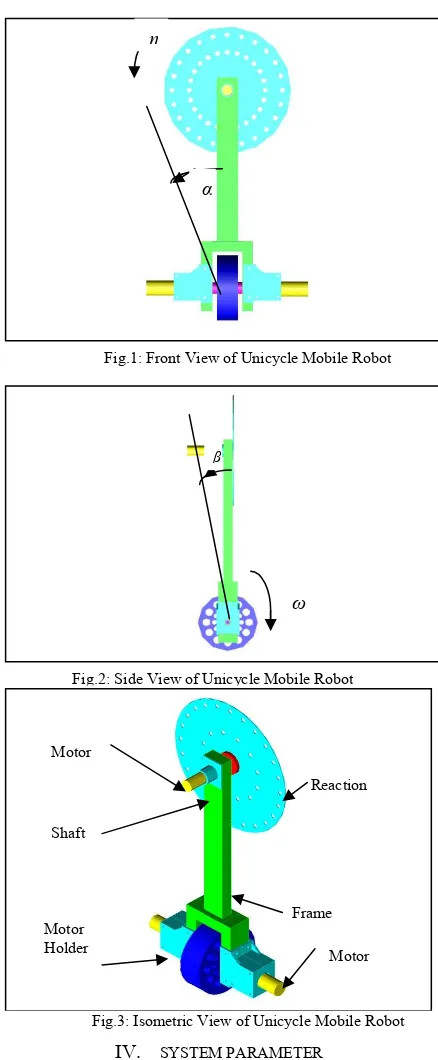
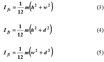
Fig.1, Fig.2, and Fig.3 show the front view, side view and isometric view of the unicycle’s design.
In Fig.1, the rotation reaction disc angle is shown by, η, while the roll angle is shown by α. The length between the centre of the wheel to the centre of the disc is shown by ld
while the length between the centre of the wheel to the centre of the gravity is shown by lf.
In another figure, Fig.2 shows the pitch angle of the robot,β, and the wheel angle, ω. Fig.3 shows the complete isometric view with the system interconnection.
IV. SYSTEM PARAMETER
After the design of the robot has been accomplished, the robot’s system then is fabricated. Then the system is integrated with the electrical component, sensors, motor drivers and etc. From the complete system, the unicycle mobile robot’s perimeters can be measured.
The measured parameters are the mass moment of inertia for the unicycle’s wheel, frame and reaction disc, and the system’s centre of gravity. The mass moment of inertia can be said as the resistance of an object to the angular acceleration and it is depended on the mass and the geometry of the object [8].If the mass moment of inertia is
α η
β
ω
Reaction Motor
Shaft
Motor Frame Fig.1: Front View of Unicycle Mobile Robot
Fig.2: Side View of Unicycle Mobile Robot
Fig.3: Isometric View of Unicycle Mobile Robot Motor
not located at the centre of the mass but at certain distance from the centre of mass, d, the parallel axis theorem is used. The centre of gravity can be described as the average location of the weight of an object. In the calculation of mass moment of inertia and the centre of gravity for the unicycle system, a few parts such as screws, rivets, shafts and motor holders are treated as integrated parts in the wheel, frame and reaction disc. The reason for such assumption is to simplify the calculation.
By using the mass moment of inertia formula for a cylinder, we can calculate the mass moment of inertia for the wheel which is given as:
2 2 1
w w
wy m r
I = (1)
). 3
( 12
1 2 2
w w w wx
wz I m r l
I = = + (2)
where Iwy is the mass moment of inertia for wheel in y direction, and Iwx and, Iwz are the wheel mass moment of inertias in x direction and z direction respectively.
By using the Eqn.(1) and Eqn.(2), the mass moment of inertia for wheel is calculated as shown in the Table 1:
Table 1: Mass and mass moment of inertia for unicycle mobile robot’s wheel.
Name List of
symbol Value Unit
Mass of wheel mw 0.672 kg
Radius of wheel rw 0.075 m
Base width of wheel lw 0.05 m
In x direction Iwx 0.001085 kgm2
In y direction Iwy 0.00189 kgm2
In z direction
I
wz 0.001085 kgm2In order to calculate the properties parameter of the frame, the frame has been segmented into a few parts; part A, part B, part C, part D and part E. The frame is assumed to be in solid rectangular shape.
The general formulas to calculate the moment of inertia for rectangle are given by Eqn.(3) – (5).
(
2 2)
12 1
w h m
Ifx= + (3)
(
2 2)
12 1
d h m
Ify = + (4)
(
2 2)
12 1
d w m
Ifz= + (5)
The mass moment of inertia for every mentioned part can be calculated by using these formulas, together with the properties of unicycle frame which are listed in Table
2 and Table 3. The mass moment of inertias for frame are listed in Table 4.
Table 2: Dimensions of unicycle mobile robot’s frame segments.
Segment Height ,h Width, w Depth, d Unit A 0.385 0.050 0.025 m B 0.025 0.090 0.05 m C 0.165 0.025 0.05 m D 0.165 0.025 0.05 m E 0.060 0.110 0.06 m F 0.060 0.110 0.06 m
Masses of the segments are listed in Table 3.
Table 3: Masses of unicycle mobile robot’s frame segments.
Segment Mass, m Unit
A 0.137 kg B 0.048 kg C 0.118 kg D 0.118 kg E 0.641 kg F 0.641 kg
Total 1.710 kg
Table 4: Mass moment of inertias for every segments of unicycle mobile robot’s frame in x, y and z.
Segment Ifx Ify Ifz Unit
A 1.72x10
-3 1.70x10⁻³
3.56
x10-5 kg.m 2
B 3.49x10
-5 1.25x10⁻⁵
4.24x 10⁻⁵
kg.m2
C 2.76x10
-4 2.95x10⁻⁴
3.1x 10
-5 kg.m
2
D 2.76x10
-4 2.95x10⁻⁴
3.1x 10
-5 kg.m
2
E 8.4x10⁻⁴ 3.85x
10-4 8.4x10
-4 kg.m2 F 8.4x10⁻⁴ 3.85x10⁻⁴ 8.4x10⁻⁴
kg.m2 However, since all the moment of inertia mentioned in Table 4 should be relative to the centre of the wheel, the parallel axis theorem must be used in order to obtain the more accurate mass moment of inertia for the unicycle frame.
By using this theorem, the moment of inertia for every segment A, B, C, D, E and F, relative to the centre of the wheel can be calculated based on this general formula Eq. (6):
2
df f f
f I m l
I ′ = + (6)
where:
mf is the mass of the frame and l.
ldf is perpendicular distance between the parallel axis. The moment of inertia for segments A, B, C, D, E and F relative to the centre of wheel are given as shown in the Table 5.
Table 5: Mass of inertias for every segment of unicycle mobile robot’s frame and parallel axis theorem.
Segment
0.0575 0.0375 0.0575 6.70
x10-04
0.0575 0.0375 0.0575 6.70
x10-04
By combining all the individual mass moment of inertia for frame, A, B, C, D, E and F, single mass moment of inertia for unicycle’s frame is given as in Table 6.
Table 6: Final value for moment of inertias for unicycle mobile robot’s frame in x, y and z direction
Name List of
symbol
Value Unit
Mass moment of inertia for frame in x direction
′ fx
I 4.71x10-02 kgm2 Mass moment of inertia for
frame in y direction
′ fy
I 1.94x10-02 kgm2 Mass moment of inertia for
frame in z direction
′ fz
I 3.15x10-02 kgm2
The reaction disc is assumed to be a thin disc. The total mass of this reaction disc is the combination of the mass of the disc, the reaction masses, mass of the motor and mass of the motor holder. Besides that, the masses for the shaft to hold the reaction disc with the motor and motor holder are assumed to be very small and negligible.
The equations used to calculate the mass moment of inertia for a thin disc are provided as Eqn.(7) – (9):
2
The mass moments of inertia for the reaction disc with respect to the centre of the wheel are given as Eqn. (10) – Eqn. (12):
rdis the radius of the reaction disc.
ldd is the distance between centre of the reaction disc to the centre of the wheel which again based on parallel axis theorem.
The parameters of the unicycle mobile robot for Eqn. (10) – Eqn. (12) are shown in Table 7 and Table 8.
Table 8: Parameter for unicycle mobile robot’s reaction disc
Name List of
symbol
Value Unit
Mass of reaction disc. md 0.396 kg
Radius of reaction disc. rd 0.15 m
Distance from centre of wheel to centre of reaction disc
ldd 0.5 m
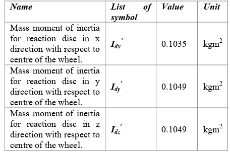
Table 9: Mass moment of inertias for reaction disc with parallel axis theorem in x, y and z direction
Name List of
symbol
Value Unit
Mass moment of inertia for reaction disc in x direction with respect to centre of the wheel.
Idx’ 0.1035 kgm2
Mass moment of inertia for reaction disc in y direction with respect to centre of the wheel.
Idy’ 0.1049 kgm2
Mass moment of inertia for reaction disc in z direction with respect to centre of the wheel.
Idz ’
In order to locate the centre of gravity for this unicycle mobile robot, the volume and centroid for every sub components need to be calculated. The formula to calculate the centre of gravity for this system is shown in the Eqn. (13).
The volume for the wheel and reaction disc can be calculated as the volume of cylinder which is provided by the formula below:
h
For the unicycle frame, volume can be calculated as rectangular parts.
d w h
V = * * (15)
where:
h is the height of the individual parts.
w is the width of the individual parts.
d is the depth of the individual parts.
Since the system is symmetric, the centroid of unicycle only available along z axis. The centroid of each parts are measured based on the distance from the x and y axis of the wheel. The summary for the centroid of every parts are listed in the Table 10.
Table 10: Summary for the centroid for every subsystem at the unicycle mobile robot
Centroid Value Unit
Wheel 0 m
By using Eqn.(13), the centre of gravity for the system can be calculated as:
Centre of
gravity = 0.16m from centre of the wheel. the system can be designed. The purpose of this validation is to ensure the system is controllable. All the parameters acquired are included into the dynamic
V. VALIDATION
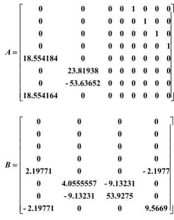
The system parameters that have been calculated in section IV need to be validated before the controller for modeling for unicycle mobile robot mentioned in [1]. The nonlinear model mentioned in [1] is:
τ
Eqn. (16) then is linearized by using Jacobian linearization. The nonlinear model that has been linearized with respect to the desired operating point can be described as:
x which is the upright position of the unicycle robot..
VI. RESULTSANDDISCUSSION
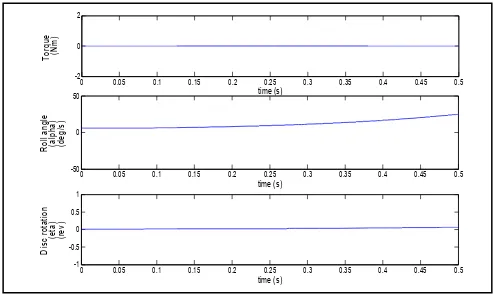
The Eqn. (17) with the real hardware parameters are simulated using simulation environment in the Matlab. There are four test cases investigated; (a) roll angle without torque applied, (b) roll angle with torque applied, (c) pitch angle without torque applied and (d) pitch angle with torque applied as shown in Fig.4, Fig.5, Fig.6 and Fig.7 respectively. Fig.4 shows that; when there is no torque applied to the reaction disc, the unicycle can be seen to fall to the +y direction from the upright angle and reach roll angle, α=30° at time, t=0.5s while the reaction disc rotates to the clockwise direction due to gravitational effect.
In another figure, Fig.5 depicts that the unicycle motion to the +y direction increases when torque is applied to reaction disc. The reaction disc rotates in the counter clockwise and causes the unicycle to drop faster in +y direction (roll angle increases). Whereby, compared to the previous result at time, t = 0.5s, now the roll angle, α which starts at position +6° increases towards 50° and the reaction disc rotates -0.3rev or -108°.
For the analysis in the pitch direction, without applying any input torque applied to the wheel, the unicycle frame
and disc takes longer time to fall as shown in Fig.6. This shows that the wheel moves backward while the frame together with the disc falls forward.
When the torque, τw which is applied to the wheel, it causes the frame and the disc to fall in the opposite direction to the wheel rotation From the Fig.7, the frame angle, β reaches -30° with the same period of time, t =0.5s while the wheel has rotated one revolution or, ω = 360° at t = 0.5s.
VII. CONCLUSION
In a nutshell, the unicycle mobile robot has been designed and fabricated. The parameters from the unicycle’s hardware model then have been calculated. The purpose of obtaining the parameters from the real hardware is to ensure the system conforms to the mathematical model developed previously.
REFERENCES
[1] M.Z Ab.Rashid and S.N Sidek, Dynamic Modeling and Verification
of Unicycle Mobile Robot System ,4th International Conference on Mechatronics (ICOM), 17-19 May 2011, Kuala Lumpur, Malaysia.
[2] Schoonwinkel,A, Design and Test of a Computer Stabilized Unicycle.
Ph.D dissertation, Stanford University,CA, 1987.
[3] Sheng,Z.Q.,Yamafuji,K. and Ulyanov.S, Study on the Stability and
Motion Control of a Unicycle Robot, (3rd report, Characteristics of a
unicycle robot), The Japan Society of Mechanical Engineers, Series C, Vol.39, No.3, 1996.
[4] Usui,S., Kamoshita,S. and Nagata,Y, Postural Stabilization of a
Unicycle, Transactions of the Japan Society of Mechanical Engineers. C 03875024 The Japan Society of Mechanical Engineers, 1996.
[5] Benjamin,H.B.Jr. and Yansheng,Xu, A Single Wheel Gyroscopically
Stabilized Robot, Proceedings of the 1996 IEEE, International Conference on Robotics and Automation, Minneapolis,Minnesota, 1996.
[6] Nakajima., R,Takashi,T., Yuta,S. and Koyanagi,E.. A Development of
a New Mechanism of an Autonomous Unicycle, Proc. IROS 97 0-7803-41 19-8/97 IEEE, 1997.
[7] Lauwers, T. B.,Kantor, G.A. and Hollis,R.L.. A Dynamically Stable
Single-Wheeled Mobile Robot with Inverse Mouse-Ball Drive. Proc. IEEE Int’l. Conf. on Robotics and Automation, Orlando, FL, 2006
0 0.05 0.1 0.15 0.2 0.25 0.3 0.35 0.4 0.45 0.5
Fig.4: Validation of System Parameter using Roll angle, α (deg) and reaction disc rotation angle,η (rev)vs time (s) without torque applied
Fig.5: Validation of System Parameter using Roll angle, α (deg) and reaction disc rotation angle,η (rev)vs time (s) with torque applied
Fig.6: Validation of System Parameter using Pitch angle, β(deg) and wheel rotation angle,ω (rev)vs time (s) without torque
applied