UNIVERSITI TEKNIKAL MALAYSIA MELAKA
SECURITY HAZARDS ALERT AND PREVENTION SYSTEM IN
SPECIFIC AREA IN INDUSTRY BY USING GSM
This report submitted in accordance with requirement of the Universiti Teknikal Malaysia Melaka (UTeM) for the Bachelor's Degree in Electronics Engineering
Technology (Industrial Electronics) with Honours
by
AHMAD SALWAN BIN YAHAYA
B071110135
920503025835
UNIVERSITI TEKNIKAL M
1. Laporan PSM adalah hak milik Universiti Teknikal Mal 2. Perpustakaan Universiti Teknikal Malaysia berkenaan dengan menyat akan SULIT at au TERHAD.
UNIVERSITI TEKNIKAL MALAYSIA MELAKA
BORANG PENGESAHAN STATUS LAPORAN PROJEK SARJ
Security Hazards Alert And Prevention System In Specific Industry By Using GSM
2014/15 Semester 1
AD SALWAN BIN YAHAYA
mengaku membenarkan Laporan PSM ini disimpan di Perpustakaan U
Malaysia Melaka (UTeM) dengan syarat-syarat kegunaan seperti berikut:
Laporan PSM adalah hak milik Universiti Teknikal Malaysia Melaka dan penulis. Perpustakaan Universiti Teknikal Malaysia Melaka dibenarkan membuat salin untuk tujuan pengajian sahaja dengan izin penulis.
Perpustakaan dibenarkan membuat salinan laporan PSM ini sebagai baha pertukaran antara institusi pengajian tinggi.
TIDAK TERHAD
iii
DECLARATION
I hereby, declared this report entitled “Security Hazards Alert and Prevention System in Specific Area in Industry by Using GSM” is the result of my own research except
as cited in the references.
iv
APPROVAL
This report is submitted to the Faculty of Engineering Technology of UTeM as a partial fulfillment of the requirements for the degree of Bachelor's Degree in Electronics Engineering Technology (Industrial Electronics) with Honours. The member of the supervisory is as follow:
v
ABSTRACT
vi
ABSTRAK
vii
DEDICATION
viii
ACKNOWLEDGEMENT
First and foremost, I would like to take this opportunity to express my sincere acknowledgement to my supervisor Encik Ahmad Nizam Bin Mohd Jahari @ Mohd Johari from the Faculty of Engineering Technology, Universiti Teknikal Malaysia Melaka (UTeM) for his essential supervision, support and encouragement towards the completion of this project.
ix
2.2 Main Equipment used in this project 7
2.2.1 GSM technology 7
2.2.2 GSM architecture 8
2.2.3 GSM Modem: MOD 9001D RS232 GSM/GPRS Modem 9
2.2.4 Microcontroller 10
2.2.5 PIC Microcontroller: PIC16F877A 11 2.2.6 Liquid Crystal Display (LCD) 12
2.2.7 Gas Sensor 13
2.2.8 Temperature Sensor 14
x 2.2.9.1 Recommended Relative Humidity (RH) in production 17
and process environments
CHAPTER 3: MATERIALS AND METHODS/METHODOLOGY 20
3.1 Introduction 20
3.2 Project Planning 22
3.3 Software Development 26
3.3.1 Programming Tools: CCS C Compiler for PIC 26 3.3.2 Microsoft Visual Basic to Create Graphical User Interface (GUI) 26 3.3.3 Development of Detector Circuit 29
3.4.4 Development of Voltage Regulator Circuit 38
CHAPTER 4: RESULT AND DISCUSSION 39
4.1 Project Result 39
4.1.1 The Operation of Hardware 39
4.2 Analysis of project 52
4.2.1 Analysis of MQ-5 gas sensor 52 4.2.2 Analysis of LM 35 temperature 53
4.3 Discussion 54
CHAPTER 5: CONCLUSION & FUTURE WORK 56
5.1 Conclusion 56
5.2 Project implication 57
5.3 Recommendation for future work improvements 57
xi
APPENDICES
A Coding of project
B Gantt chart of final year project activities in FYP 1 and FYP 2 C Poster for presentation of project
xii
LIST OF TABLES
2.1 Function pin of LCD 13
2.2 Recommended Relative Humidity (RH) in some common production 18 and process environments
3.1 Project activities for FYP 1 and FYP 2 23 3.2 Gantt chart of project activities for FYP 1 23 3.3 Gantt chart of project activities for FYP 2 24
xiii
3.1 Flowchart of procedure project in FYP 1 21 3.2 Flowchart of procedure project in FYP 2 22
3.3 Block diagram of project 25
3.4 CCS C Compiler for PIC 26
3.5 Design form in Microsoft Visual Basic 27 3.6 Coding in Microsoft Visual Basic 28 3.7 The Private Sub (start) and End Sub (end) 28 3.8 Form of Graphical User Interface (GUI) 29 3.9 Proteus Design Suit 8.0 software 30 3.10 Circuit constructed using ISIS Proteus Software 30 3.11 PCB Layout using ARES Proteus Software 31 3.12 USB ICSP PIC Programmer UIC00B 32
3.13 PICkit 2 Programmer 33
3.14 Ultra Violet Light Machine 34
3.15 Developing process 35
3.16 Machine for etching process 36
3.17 PCB board after etching process 37
3.18 Drilled process 37
xiv 4.1 Flowchart of project hardware operation 41 4.2 The prototype of the project from in front side 42 4.3 The prototype of the project from upper side 42 4.4 The Set-up of prototype with computer and GSM modem 43 4.5 The system is switched on supply voltage 44
4.6 USB to RS 232 serial port 45
4.7 Graphical User Interface (GUI) 46
4.8 The sensor MQ-5 detect LPG gas 47
4.9 The reading of gas sensor detect in site 48
4.10 SMS send to user 48
xv
LIST OF ABBREVIATIONS, SYMBOLS AND
NOMENCLATURE
AUC - authentication center A/D converter - analog to digital converter BTS - base transceiver station BSC - base station controller FYP - final year project
GSM - global system for mobile communications GUI - graphical user interface MAX 232 - dual driver or receiver
1 This chapter covered project’s background, objectives, problem statement, scope of the project and project result. Overview of methodology used was stated. The organization of this report also explained in this chapter.
1.1
Background
This project is microcontroller interface with Graphical User Interface (GUI). The controller system, Global System for Mobile Communications (GSM) modem and GUI is installed at maintenance room in industry which controlled by safety officer worker. The sensors used are temperature, humidity, and gas sensor. This project is to monitor the dangerous temperature, humidity, and gas in different area site which are site 1 and site 2. The GUI is creating to update the number of phone of receiver and it function to send the message in form of Short Message Service (SMS) to give information of dangerous temperature, humidity, and gas. The alert system which installed at each site 1 and site 2 are buzzer and light emergency. For the prevention system, each site 1 and site 2 are installed with exhaust fan which it trigger when detect the dangerous temperature and Liquid Petroleum Gas (LPG). In this project there are mainly three units, microcontroller unit, GSM modem and the GUI which controlled in computer. Microcontroller used to send the output of dangerous temperature, humidity, and gas using serial port RS 232. Then the information is reading in GUI and it sends the information by SMS on updated number using GSM modem. GSM modem can be configured by standard GSM AT command set for sending and receiving SMS and getting modem status. In the
3
1.3
Objective
The objectives for this project are to:
(a) design and develop system in monitoring hazards of dangerous temperature, humidity and gas in industry
(b) maintain the safety in industry by create the new system which can be used in alert and prevent hazard
(c) make system which produce faster information about hazard in industry
1.4
Scope
4
1.5
Project Significant
The system can detect dangerous temperature and humidity and gas at specific area in industry which involve different site. The sensor has excellent sensitivity combined with a quick response time. The gas leakage, dangerous temperature and humidity detected are messaged to the authorized person like technician or safety officer worker using cellular network called GSM. Sending written text messages is very popular among mobile phone users. Instant messaging, as it is also known, allows quick transmission of short messages that allow an individual to share ideas, opinions and other relevant information. This system also use the GUI that function to exchange phone number of user and send the information to GSM modem that act to send massage to user.
1.6
Conclusion and Summary
5
1.7
Report Outline
In this report, there are five chapters which will briefly explain all the efforts and flows in completing this project.
Chapter 1 introduces the background knowledge of the project, explains work scope of the project, for instance, problem statements, objectives and the scope of the project has been briefly defined in this chapter.
Chapter 2 explains the basic knowledge of GSM technology and also reviews related information of hardware equipment used such as temperature sensor LM 35, humidity sensor SN-HMD-MOD, and gas sensor MQ-5. The information of microcontroller used also explained in this chapter. All information was got from reading books, journal article, conference proceedings, and other sources.
Chapter 3 states the methodology taken to complete this project successfully with a given period of time. In this chapter also will give a details work schedule in terms of Gantt chart for Final Year Project (FYP 1) and (FYP 2), project planning, block diagram of project and the brief descriptions for this project.
6 This chapter explains the basic knowledge of GSM technology and also reviews the related information of hardware equipment used such as temperature sensor LM 35, humidity sensor SN-HMD-MOD, and gas sensor MQ-5. The information of microcontroller used also explained in this chapter. All information was got from reading books, journal article, conference proceedings, and other sources.
2.1
Related work using GSM
This section describes some earlier works related to the monitoring system using GSM network services.
The work presented by Islam et al. (2009), has developed a Prepaid Water Meter System for prepaid billing of water consumption through remote monitoring without any human intervention. This system promises may be fast and accurate billing of water as well as preventing any misuse of it. This project is can save energy and time of user to monitor the quantity of water used and it prepaid billing. In this Final Year Project (FYP), it was used the Global System for Mobile Communication (GSM) as a method to monitor hazard in industry with faster information.
However, according to Abd Wahab et al. (2011), developed a water meter reading using GSM network that appropriate for remote places to monitor the water meter reading before any billing process. This could reduce the use of human
7 resource for reading the meter and issuing a bill. There was also a work on monitoring of electrical meter reading using GSM network done. The system was capable of monitoring the meter reading and sent an SMS to the authorized center for billing purpose. This could reduce the number of estimated reading when the authorize person unable to reach the meter. The project before only monitor the output in one place but for this FYP project, it involve more than one place to monitor hazard at a time.
According to Landolsiet al.(2010), using wireless text messaging system to send early warning SMS messages to users advising them to proactively reduce their power consumption before system capacity is reached and systematic power shutdown takes place. This could increase cost-effective wireless distributed load shedding system for non-emergency scenarios. The project above has same application in this FYP project which it come with the prevention after the hazard was detected like when the system detect LPG gas, the exhaust fan will on automatically to exhaust the gas outside the industry building.
2.2
Main Equipment used in this project
This project consists of several main equipment which are GSM modem, microcontroller PIC16F877A, Liquid Crystal Display (LCD), gas sensor, temperature sensor, and humidity sensor.
2.2.1 GSM technology
8 Today’s second generation GSM networks deliver high quality and secure mobile voice and data services such as SMS with full roaming capabilities across the world.
According to Jayanta Kumar Pany et al. (2011), GSM platform is a hugely successful technology and as unprecedented story of global achievement. In less than ten years since the first GSM network was commercially launched, it become, the world’s leading and fastest growing mobile standard, spanning over 173 countries. Today, GSM technology is in use by more than one in ten of the world’s population and growth continues to sour with the number of subscriber worldwide expected to surpass one billion by through end of 2003.
GSM platform is used for living, growing and evolving and already offers an expanded and feature-rich ‘family’ of voice and enabling services. The GSM network is a cellular telecommunication network with a versatile architecture complying with the ETSI GSM 900/GSM 1800 standard. Siemens' implementation is the digital cellular mobile communication system D900/1800/1900 that uses the very latest technology to meet every requirement of the standard.
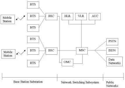
2.2.2 GSM architecture
9 Figure 2.1: GSM architecture
2.2.3 GSM Modem: MOD 9001D RS232 GSM/GPRS Modem
GSM modem is a wireless modem that works with GSM wireless network, which used the radio waves interface to send and receive data. This GSM modem needed Subscriber Identity Module (SIM) card in order to function. Moreover, to control the function of GSM modem, AT command is used. Basically, AT commands is a standard command for GSM modem, which will allow it to perform various commands such as:
(a) Read, write and delete SMS (b) Send SMS
(c) Monitor the signal strength