DOI: 10.12928/TELKOMNIKA.v14i3A.4428 9
Design and Application of Coupling Power Supply
Device on Overhead Ground Wire
Qianbo Xiao*, Haibing Zhang, Wei Song, Bangfei Deng
Electric Power Research Institute of State Grid Chongqing Electric Power Company, Chongqing, 401123, P. R. China
*Corresponding author, e-mail: jiyongxiayajia@yeah.net
Abstract
For limited on-line monitoring application of electric transmission line which is caused by communication in addition to tower power supply stability, and closed space plane composed of two lightning protection ground wire and iron tower in alternating magnetic field cutting of overhead transmission line which will generate a certain inductive power in the plane, ground coupled power is on-line monitoring system power that converts ground wire network loss to sustainable power supply. In this paper, based on the comparison of advantages and disadvantages of several coupling power supply design, efficient power electronics energy solutions to deal with wide induction voltage and typical engineering applications for different load conditions, voltage grade and tower type are emphatically introduced.
Keywords: Overhead Ground Wire, Coupling Power Supply, On-Line Monitoring, Lightning Protection
Copyright © 2016 Universitas Ahmad Dahlan. All rights reserved.
1. Introduction
With rapid development of national economy, demand for electricity from all walks of life is growing, and also requirement for power supply quality of power supply departments (stability, uninterrupted and accompanying services). Smart grid development and popularity, and rising voltage level of transmission lines put forward higher requirements for real-time security of high voltage transmission lines, which makes real-time monitoring of state parameters of power transmission line become aninevitable trend [1].
Seen from present implementation of condition monitoring system of transmission lines, some results are achieved, but due to limitations in technical route, cost control and field environment, large-scale popularization and application are impossible. One very important constraint is problem of power: According to survey result of on-line monitoring device operating conditions of national grid system transmission line by China Electric Power Research Institute (EPRI), operation stability of monitoring device is less than 20%.
Transmission line is with such characteristics as complex environmental conditions, long-term supply difficulties, high maintenance workload, high requirement for level of security and reliability. With increasing requirements for on-line status monitoring, multiple on-line monitoring systems such as image, ice, lightning arrester, brandish, and dirty have been configured. The following four ways of power supply are mainly applied: solar energy, wind energy, lithium battery and high voltage coupling. The main disadvantages of these power supply modes are poor economy, small output power and large device volume [2].
There exists common deficiency in wind power and optoelectronic systems. The first is uncertainty in resource and energy output, the second is high dependence on battery whose life lasts about 3 years, with 20-30% capacity decline after 3 years. Low temperature performance is significantly decreased. Both lead-acid and gel battery are with output close to zero or 15-20% at-15 C degrees or below. Lithium battery power supply, due to need in regular change, is mainly used for milliwatt micro power monitoring device, inappropriate for high power on-line monitoring system of transmission line; high-voltage coupling power supply system is installed in high-voltage lines, with use limited to high pressure side, whose energy thus can not be output for usage.
concentrated in theoretical analysis, such as feasibility of coupling power supply with ground wire, effect of brandish on ground wire induction, etc.
This paper proposes scheme of coupling power supply system on overhead ground wire based on a new model of transmission line, establishes coupling electric device modeling according to “Design Manual of High-Voltage Transmission Line in Electric Power Engineering (Second Edition)”, and through calculation and analysis of ground wire induced electricity loss, case selection of power supply system, puts forward solution to some key problems of the system. Through development of prototype and its network operation, the paper analyzes actual installation and operation data, verifies the scheme and determines system optimization and improvement direction.
2. Working Principle of the System
AC magnetic field of transmission line can generate circulation between transmission line ground wire and earth through plane resulted in space cutting wire and tower; as the wire produces a magnetic field in space through alternating current, magnetic field cuts two lightning protection ground wire and thus produces induced electromotive force on the ground wire, as Figure 1. Currently for 500kV line, when conditions permit, single point grounding scheme is generally applied, mainly to reduce loss of ground induced electric energy. Once tower grounding is applied, as there exists electromotive force induced by wire current in ground wire, current will certainly be produced, thereby resulting in power loss. Therefore, induced electricity of ground wire has been regarded as negative impact of transmission line. In this project, ground wire induced electricity which has been regarded as loss is effectively utilized, so that it becomes a reliable power supply for transmission line on-line monitoring device.
Coupling Power Supply
Tension Tower
Linear Tower
Linear Tower
Linear
Tower Tension Tower
Figure 1. Working principle of the system
According to “Design Manual of High-Voltage Transmission Line in Electric Power Engineering (Second Edition)”, when busbar current of transmission line is 436A, 376 watts of power loss will be generated per1 km of ground loop. Based on this theory, 1 / 2 power can be supplied, i.e. 188 W power output; However, ground induced voltage fluctuates greatly along with change of operation state, and the system directly coupled linked with ground circuit may be easily damaged by lightning. Therefore, in addition to design of power supply module with exclusive patented technology, focus is on design of wide voltage transformation module and multi level measures of anti lightning stroke.
3. Introduction of System Implementation Method
3.1. Calculation and Analysis of Ground Wire Induced Electric Loss
According to “Design Manual of High-Voltage Transmission Line in Electric Power Engineering (Second Edition)”, ground wire induced electric loss of 1km ground loop for 220kv wire when busbar current is 436 ampere is calculated and analyzed:
2 2
2) Model of induced electromotive force of ground loop per kilometer:
1
3) Self impedance of ground loop per kilometer:
12
11 Xin 0.145 lg
r d
Z R j j (3)
In the formula: R+jXin is self impedance of single ground wire, j0.145lg (d12/r) is mutual impedance (Euro) between ground wire; d12 is ground wire spacing (m); r is equivalent radius (m) of ground wire.
4) Ground circulation calculation:
11
5) Loss per kilometer:
2 2
2 2 10.46 1.7 372
P I Ri W (5)
From the above calculation results, we can see that in the example, when busbar current is 436 ampere, loss per kilometer of ground wire is 372W. If power supply designed by us and ground impedance achieve matching state, then, in the line status, maximal 50% power of 186W can be obtained. According to linear derivation, output power of 2 2W can be obtained when busbar current is 150 ampere. From the above analysis, we can see that it is feasible to obtain energy through ground wire induction in theory. Of course, in actual use, complete matching with transmission line resistance is difficult to be achieved, so obtained power is considerably less. Through laboratory simulation test, by connection to ground wire with transformer under the same resistance condition, obtained power is 10% to 20% of maximum power to be provided by ground wire. Even so, we are still able to see that power supply can reach a few watts to dozens of watts through ground wire coupling. Output power of this magnitude can meet needs of most transmission line on-line monitoring devices.
3.2. Selection of Power Supply Scheme of Power System
Ground power supply represents a relatively ideal power supply mode for transmission line on-line monitoring device. Design of ground power supply first faces selection of power supply ground wire [3-7].
1) Tower grounding wire, with ground wire framework shown in Figure 2.
Figure 2. Ground wire framework of Tower grounding wire
To obtain electric energy from ground wire framework in the above figure, installation of power equipment is shown in Figure 3 [6, 7]:
Load
Figure 3. Installation of power equipment
From the above picture, we can see that, for tower grounding system, power supply system should be connected in series to ground wire to obtain electric energy. At this time, power takes electromotive force and current of loop composed of linear tower 1, ground wire 1, coupling power supply system, linear tower 2 and ground wire 2. This series connection method will obviously change the structure of the existing ground wire.
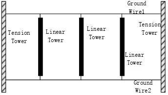
2) For single point grounding wire without OPGW, its ground wire framework is shown in Figure 4.
Figure 4. Ground wire framework for single point grounding wire without OPGW
In the picture above, a loop is formed by ground wire 2, tension tower 1, ground wire 1, coupling power supply system, linear tower 2 and short circuit. Power supply system obtains power through electromotive force and electric current generated by the loop. In this structure, body mechanism of ground wire has not been changed.
Load
Figure 5. Installation of power equipment
3) For single point grounding wire with OPGW, power supply equipment installation is shown in Figure 6.
Figure 6. Power supply equipment installation for single point grounding wire with OPGW
The power supply method is similar to that of Figure 5, but it does not need external connection to shorting stub, which has less influence on the original circuit.
4) For two-point grounding wire with OPGW, power supply equipment installation is shown in Figure 7:
Tower3 Linear Tower2
Linear
Theory of power supply with two-point grounding wire system differs from the previous several ways. Obtained electric power is remaining energy after mutual offset of “loop 1” composed of tension tower 2, ground wire 1, ground wire 2, linear tower 3 and coupling power supply and “loop 2” composed of linear tower 3, coupling power supply, ground wire 1, tension tower 1 and ground wire 2. Power supply theory of two-point grounding wire framework without OPGW is similar to that of Figure 6, hence no description is needed.
Through power supply requirements of the above several ground structures, we can see that ground wire framework of single point grounding is most suitable for installation of ground wire coupling power supply. Two-point grounding system has more considerations in power supply installation. But these two ground structures basically do not need to change existing ground wire framework in installation of power supply, while tower grounding wire need to be connected in ground wire network in series. Therefore, ground wire coupling power supply system with PT method is more suitable for single point grounding system.
3.3. Key Technology of the System 1) Lightning Protection
Due to coupling power supply on overhead ground wire, multi-level measures of lightning protection such as discharge gap, nonlinear resistor, looped network shield is designed for the device, with lightning withstand level not less than 120ka. Finally, lightning residual voltage reaching power system is less than transformer protection level, which thus achieves the effect of protection of power and back-end equipment.
Discharge Gap
Level 1 Decoupling Device
Power Supply Decoupling Lightning
Arrester
Lightning Arrester Level 2Decoupling
Device Lightning Protection
Ground Wire Insulator
Figure 8. Theory of multilevel decoupling scheme for lightning protection
Through 3 level discharge, lightning residual voltage reaching input end of power is <1500V, thus achieving equipment effect of lightning protection.
2) Voltage Transformation and Voltage Stabilization
In view of big fluctuation of induced voltage of overhead ground wire, power supply device adopts wide adaptive transformer device and voltage stabilizing device, which can meet requirements for induced voltage of overhead transmission lines of different voltage level of AC 110kV and above. The specific method is to apply dynamic voltage adjustment technology based on input voltage before voltage-stabilized source of PWM, which automatically boosts when the input voltage is low, and automatically reduces voltage when the input voltage is too high. Application of this technology can ensure that input voltage with fluctuation in a wide range can be adjusted to safe operating range appropriate for conventional PWM chip.
3) Magnesium Based Battery
Considering operation of monitoring device during line outage, magnesium battery is connected in parallel with the monitoring device to meet requirement for normal operation of the monitoring device during line outage. Energy density of magnesium based battery is 230Wh/kg, which can be used in the environment of -40 ~ 85Ԩ. Combination of charge and discharge characteristics of the battery and super capacitor can achieve high efficiency charging
4. Results and Analysis
4.1. Relationship between Working Mode of Coupling Power Supply and Current in Wire Operation mode of coupled power supply depends on induced voltage as Table 1, but is also related to different tower types, voltage levels and grounding modes:
- Under the mode of 2:1 and 1:1 charge and discharge time ratio, discharge time is designed to be 230 seconds (with load average power at 20W);
- Regardless of 2:1 or 1:1 charge and discharge time ratio, charge time is inversely proportional to the line load.
Table 1. Working conditions of ground coupled power supply
Current in Wire 50-120A Current in Wire 120-400A Current in Wire above 400 A
Charge and discharge mode of 2:1 charge time ratio.
Charge and discharge mode of 1:1 charge time ratio.
Support 24h full real-time discharge mode, while with battery filling.
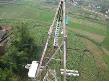
4.2. Prototype Installation
We deploy five sets of image monitoring equipment with ground coupled power supply in the southwest. From installation, commissioning to the present, the device has been in stable operation. Equipment GPRS connection has been relatively good, and can return a number of clear pictures of 2 million pixels according to the setting every day, which reflects that ground coupled power supply, has been relatively stable and sustained. Seen from operation of the equipment at the present stage, the power supply system enjoys a certain practicality.
4.3. Problem Exposed in Prototype Operation
Prototype pilot operation process exposes some problems, such as requirements for ground wire structure, relatively stringent requirement for installation process, insufficient protection of equipment in misoperation, etc. Preparatory work of installation has much higher requirement for existing photovoltaic power system. Also, monitoring point selection is limited. But to adapt to the requirements of DC ice melting in pilot application in the southwest, tower grounding wire should be gradually replaced by single point grounding wire. Hence, from point of view of long-term development, there will be more and more power transmission lines suitable for installation of coupling ground wire power supply.
Preliminary operation data shows that if device with coupling ground wire power supply can be applied to the existing transmission line as supplement to photovoltaic power system in on-line monitoring system, reliable operation rate of the existing equipment in the winter, continuous overcast and rainy days and severe weather can be improved.
5. Conclusions and Outlook
This paper presents a new type of transmission line coupling power supply system on overhead ground wire. Actual network operation shows that the system is suitable for AC transmission line installed with lightning protection grounding wire with voltage grade at 110kV and above. Without affecting the original line conditions, the system obtains energy by coupling parallel wire, completes 12VDC/20W output power supply for low voltage side equipment through super capacitor in cooperation with magnesium based battery, boasts characteristics of low fever, high stability, safe use, anti lightning, stable output, convenient installation and maintenance. It effectively avoids disadvantages of conventional power supply mode in convenient and reliable way and solves power supply problem in long-term work of field equipment.
For problems such as not compact volume structure and imperfect fault tolerance mechanism in this system, we will make further improvement and perfection so that the system can enjoy a wider application space.
References
[1] Curkendall DW, Mareynolds SR. A Simplified Approach for Determining the Information Content of Radio Tracking Data. Journal of Spacecraft. 1969; 6 (5): 520-525.
[2] Sekhar A, Raghavendrarajan V, Kumar RH & Sasikumar M. An Interconnected Wind Driven SEIG System Using SVPWM Controlled TL Z-Source Inverter Strategy for Off-Shore WECS. Indonesian Journal of Electrical Engineering and Informatics (IJEEI). 2013; 1(3): 89-98.
[3] Jiang XL, Xie YB, Hu JL, Cao YX, Fan SH, Liu YC. Analysis of Equivalent Circuit of Power Supply with Electromagnetism of Typical Overhead Transmission Lines. Power System Technology. 2015; 07: 2052-2057.
[4] HU Mingxia. Intrusion Detection Algorithm Based on BP Neural Network. Computer Engineering. 2012; 38(6): 148-150.
[5] Habib Daryabad. Investigating the Effect of Demand Side Management on the Power System Reliability. Bulletin of Electrical Engineering and Informatics. 2015; 4(2): 96-102.
[6] Seyed Ahmad Hosseini, Mohammad Mirzaie, Taghi Barforoshi. Reliability Analysis of Surge Arrester Location Effect in High voltage substations. TELKOMNIKA Indonesian Journal of Electrical Engineering. 2014; 12(8): 5814-5826.