DOI: 10.12928/TELKOMNIKA.v11i4.1511 645
Analytical Calculation of Coupled Magnetothermal
Problem in Gas Insulated Transmission Lines
Guoxia Sun*1,2, Xiangchao Jin2, Zhiyang Xie2
1
School of Electrical Engineering, Wuhan University, 430072, China
2Foshan Power Supply Bureau, Guangdong Power Grid
No.1, Fenjiangnan Road, Chancheng District, Foshan 528000, China *Corresponding author, e-mail: [email protected]
Abstrak
Jalur transmisi gas terisolasi (GIL) adalah teknologi baru untuk menyalurkan daya melalui jarak yang jauh. Paper ini mengemukakan sebuah metode analisis untuk meneliti masalah magnetothermal tergandeng pada GIL, dengan perhitungan koefisien efek kulit pada penghantar dan selubungnya menggunakan fungsi kelvin. Hasil perhitungan rugi-rugi daya yang diperoleh tersebut, digunakan sebagai masukan sumber panas pada analisis termalnya. Dengan mempertimbangkan efek perpindahan panas secara konveksi dan konduktif, maka dapat diperoleh persamaan kesetimbangan panas pada penghantar dan selubungnya. Paper ini diperluas dengan meneliti peningkatan suhu pada berbagai kondisi operasi GIL. Metode ini kemudian divalidasi dengan menggunakan metode finite element (FEM). Kesederhanaan pada pendekatan metode ini dapat mendorong implementasi melalui perangkat lunak pada desain termal serta untuk memonitor kondisi GIL.
Kata kunci: analisis termal, efek permukaan, GIL, magnetothermal tergandeng
Abstract
Gas insulated transmission lines (GIL) are a new technology for transmitting power over long distances. In this paper, an analytical method (AM) is proposed to investigate the coupled magnetothermal problem in GIL. Kelvin functions are employed to calculate the skin effect coefficients of the conductor and the enclosure. The calculated power losses are used as heat source input for the thermal analysis. Considering the convective and radiation heat transfer effects, the heat balance equations on the surface of the conductor and the enclosure are established, respectively. Temperature rise of the GIL at different operation conditions are investigated. The proposed method is validated against the finite element method (FEM). The simplicity of the approach makes it attractive for self-made software implementation in the thermal design and the condition monitoring of GIL.
Keywords: coupled magnetothermal, GIL, skin effect, thermal analysis
1. Introduction
Gas-insulated transmission lines (GIL) represent a new technology for high power transmission. Comparing with the overhead lines and XLPE-insulated cables, the advantages of GIL are obvious [1-3]. The power transmission capacity of GIL is comparable with overhead lines, while the transmission losses are much lower. Because of the gaseous insulation, GIL has the lower reactive power, higher arc withstand capabilities and smaller transmission corridor. The most widespread structure of GIL consists of three single-phase encapsulated aluminium tubes. Each tube is composed of an outer aluminium enclosure on ground potential and of a conductor installed inside on high voltage. The annular space between the conductor and the enclosure is filled with pressurized SF6 gas or SF6/N2 (20/80%) mixture. The eddy current in
comparable magnitude and opposite direction of conductor current is induced in the enclosure, which screens the electromagnetic field of the conductor completely to the outside [4, 5].
element method (FEM), due to its flexibility in representing the field domain and dealing with complicated GIL installation conditions, has prevailed in the field of GIL modeling [1] [7]. Various implementations of FEM to thermal distribution of GIL are encountered in the technical literature. However, the FEM is time consuming for a solution when compared with FEM. It cannot be included in a design or a condition monitoring program, which may take several iterations to obtain the final result. Hence, the need for a simple and accurate model is required which can yield the temperature rise in the GIL without being computationally intensive.
Knowledge of the temperature rise plays an important role in understanding the improvement of the design process and in condition monitoring to keep GIL temperature at safety levels. The main point of this paper is to provide a simple and fast means of calculating the temperature rise of GIL. The skin effect of eddy current induced in the enclosure is considered. Results from the model are compared with finite element simulations.
2. Power Losses in GIL
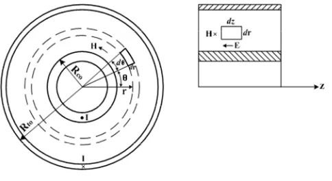
Usually, a two-dimensional (2-D) model is sufficient since the dimensions of GIL are invariant along its length. Assuming the current density has only the z-direction component and is only relative with radius r and time t, the electromagnetic field of GIL in cylindrical coordinate system (r, θ, z) is shown in Figure 1.
Figure 1. Electromagnetic field in GIL
The elements rdθdr and drdz are, respectively, in the cross section and longitudinal section of GIL. According to Ampere's circuital law and Faraday’s law of electromagnetic induction, the magnetic field intensity H and current density J at the elements can be described by Equations 1 and 2:
Where is permeability, σis the conductivity.
Based on the above equations, the magnetic field intensity and the current density can be solved with the following equations 3:
Where ω is the angular frequency.
Substituting (6) into (3) and (4), the following Bessel differential equations are obtained:
2
General solution of (7) and (8) can be expressed as
3/2 1/2 imaginary parts, respectively, of the vth order modified Bessel functions of the second kind, M and N are the amplitude, and are the phase angle.
Assuming the total current flowing in the conductor is , the following boundary conditions are used to calculate (9)
ci
The current density on the outer conductor surface is
0 co 0 co
The AC impedance of the conductor can be expressed as Equation 18.
co
The skin effect coefficient of the conductor is given by Equation 19.
2
Likewise, the following boundary conditions are used to calculate (10)
ti ti
According to the boundary conditions, the skin effect coefficient of the enclosure is given by
where Rto and Rti are, respectively, the outer and inner radius of the enclosure.
The induced current induced in the enclosure is of the same amplitude with the current in the conductor, the power losses in the conductor and the enclosure are, respectively, expressed as
3. Temperature Prediction of GIL with analytical method
Convective and radiation heat transfer effects are considered in the model. The heat generated in the GIL is transferred to the ambient air by natural convection and radiation occurred on the enclosure surface. As the narrow space between the enclosure and the conductor, the conductor is cooled down by convection and radiation occurred in enclosed space. In the model, the conductor and enclosure of GIL is assumed to be isothermal.
3.1. Convection on the Enclosure Surface
Non-dimensional parameters are usually used to analyze the convective heat transfer problem. These parameters are the Nusselt number (Nu), Prantle number (Pr) and Rayleigh number (Ra). The following equations are used to evaluate these parameters [8]:
to
NuC(GrPr)n hD / (27)
3 3
GrgTl /v (28)
Prv a/ (29)
where h is the convective heat transfer coefficient, Dto is the outer diameter of the enclosure, C
and n are constants, α is the coefficient of cubical expansion, , and are, respectively, the kinetic viscosity, thermal diffusivity and thermal conductivity of the air.
Considering geometry of GIL and characteristics of ambient air and temperature, the convection heat transfer on the enclosure surface is expressed by
tc to( t a)
Q h D (30)
where a is the temperature of the ambient air.
3.2. Convection in the Enclosed Space
The convection happened in the enclosed space between the conductor and the enclosure of GIL is complicated. Thus the effective thermal conductivity is preferable to equate convection cause by the flowing SF6 gas with heat conduction.
0.2
The thermal conductivity and dynamic viscosity of SF6 gas are temperature dependent
and are, respectively, calculated by
5 0.942
The convection heat transfer on the surface of conductor per unit length is given as Equation 34.
3.3. Radiation Heat Transfer
Radiation is the transfer of heat via electromagnetic waves. There is radiant energy exchange between the conductor and the enclosure and between the enclosure and the ambient air. The heat transfer by radiation process was found to have large effects in the overall heat transfer of GIL.
The calculation of the radiation heat transfer from the conductor to the enclosure commonly uses the formula in (35), as is mentioned in [9]
4 4
where is the Stefan-Boltzmann constant, Aco and Ati are areas of the outer conductor surface
and the inner enclosure surface, respectively, c and t are the emissivity of the conductor and
the enclosure.
The radiation heat transfer from the enclosure to the ambient air is computed as
4 4
tr t to[( t 273) ( a 273) ]
Q A (36)
where Ato is the area of the outer enclosure surface.
3.4. Thermal Computation
At steady state, the heat generated and dissipated in the GIL satisfies the following thermal equilibrium equations 37 and 38.
c t tc tr
P P Q Q (37)
c cc cr
P Q Q (38)
Equation (37) indicates that the power losses in the GIL equal the heat dissipated by convection and radiation on the enclosure surface. Equation (38) means that the loss generated in the conductor equals the heat dissipated by convection and radiation on the conductor surface.
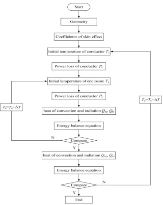
The flow chart of thermal analysis is given in Figure 2. An initial temperature is assumed to calculate the DC resistance of the conductor and the enclosure. According to the dimension parameters of GIL, the skin effect coefficients of the enclosure and conductor are calculated. Then, these coefficients are used to figure out the power losses in the conductor and enclosure. The heat of convection and radiation are calculated with (30) and (36). Equation (37) is used to compare the balance between the dissipated heat on the enclosure surface and the power loss of the whole GIL. If the error is not larger than 5%, then the heat cause by convection and radiation of the conductor are, respectively, calculated with (34) and (35). The energy balance on the conductor surface is examined, if the error is larger than 5%, the conductor temperature is updated. The final temperatures of conductor and enclosure are obtained at the end of the iteration.
4. Results and Discussion
The dimensions and thermal parameters of the GIL are, respectively, given in Table 1 and Table 2.
Table 1. Dimensions of the GIL
Components Inner diameter (mm) Thickness (mm)
Conductor 160 20
Figure 2. Flow chart of thermal analysis
Table 2. Material Properties in the thermal model of GIL
Item Density (kg/m3)
Thermal conductivity (102 W/(mK))
Dynamic viscosity (10-5 Pas)
Specific heat (J/(kgK))
SF6 gas 22.82 1.206 1.42 665.18
Air 1.293 2.44 1.72 1005
Based on the method mentioned in section 2, the skin effect coefficients of the conductor and enclosure are 1.35 and 1.21, respectively. The emissivity of the conductor and the enclosure is chosen to be 0.85. The ambient temperature is 25.1 . The current frequency is 50 Hz. When the current is in the range of 2 kA to 8 kA, the power losses and the heat dissipated by convection and radiation are given in Table 3.
Table 3. Power losses and the heat dissipated by convection and radiation
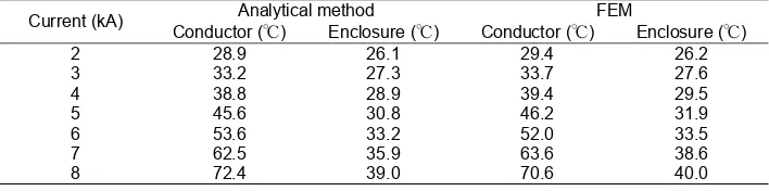
Table 4. Result comparison between the FEM and analytical method
Current (kA) Analytical method FEM
Conductor (℃) Enclosure (℃) Conductor (℃) Enclosure (℃)
This paper has presented an analytical model that provides an efficient technique for temperature prediction in GIL. The proposed methodology takes substantially less computational effort when compared with FEM. The Kelvin functions are used to calculate the skin effect coefficients of the conductor and enclosure of GIL. Temperature dependent thermal parameters and convective heat transfer coefficient are taken into account. Results from the model are validated against finite element simulations, yielding a good match. The model has proven to be sufficiently accurate and efficient for practical implementation in a design and condition monitoring program.
References
[1] Wu X, Shu N, Li H. Thermal analysis in gas insulated transmission lines using an improved finite-element model. TELKOMNIKA Indonesian Journal of Electrical Engineering. 2013; 11(1): 458-467. [2] Benato R, Dughiero F, Forzan M. Proximity effect and magnetic field calculation in GIL and in isolated
phase bus ducts. IEEE Transactions on Magnetics. 2002; 38(2): 781-784.
[3] Koch H, Schuette A. Gas insulated transmission lines for high power transmission over long distances. Electric Power System Research. 1998; 44(1): 69-74.
[4] Chakir A, Sofiane Y, Aquelet N. Long term test of buried gas insulated transmission lines (GIL). Applied Thermal Engineering. 2003; 23(13): 1681-1696.
[5] Chakir A, Souli M, Aquelet N. Study of a turbulent natural convection in cylindrical annuli of gas-insulated transmission lines 400 kV. Applied Thermal Engineering. 2003; 23(13): 1197-1208.
[6] Minaguchi D, Ginuo M, Itaka K. Heat transfer characteristics of gas-insulated transmission lines. IEEE Transactions on Power Delivery. 1986; PWRD-1(1): 2-9.
[7] Benato R, Dughiero F. Solution of coupled electromagnetic and thermal problems in gas-insulated transmission lines. IEEE Transactions on Magnetics. 2003; 39(3): 1741-1744.
[8] Kim J K, Hahn S C, Park K Y. Temperature rise prediction of EHV GIS bus bar by coupled magnetothermal finite element method. IEEE Transactions on Magnetics. 2005; 41(5): 1636-1639. [9] Kim S W, Kim H H, Hahn S C. Coupled finite-element-analytic technique for prediction of temperature