UNIVERSITI TEKNIKAL MALAYSIA MELAKA
APPLICATION OF GENERAL FLOW PATTERN IN FACILITY
LAYOUT
This report submitted in accordance of with the requirement of the Universiti Teknikal Malaysia Melaka (UTeM) for the Bachelor Degree of Manufacturing
Engineering (Manufacturing Management) with Honours.
by
NORSYAHILA BT. AHMAD SAHHIDAN
UTeM Library (Pind.1/2010)
SULIT
TERHAD
TIDAK TERHAD
(Mengandungi maklumat yang berdarjah keselamatan atau kepentingan Malaysia yang termaktub di dalam AKTA RAHSIA RASMI 1972)
(Mengandungi maklumat TERHAD yang telah ditentukan oleh organisasi/badan di mana penyelidikan dijalankan)
(TANDATANGAN PENULIS)
* Tesis dimaksudkan sebagai tesis bagi Ijazah Doktor Falsafah dan Sarjana secara penyelidikan, atau disertasi bagi pengajian secara kerja kursus dan penyelidikan, atau Laporan Projek Sarjana Muda (PSM). ** Jika tesis ini SULIT atau TERHAD, sila lampirkan surat daripada pihak berkuasa/organisasi berkenaan dengan menyatakan sekali sebab dan tempoh tesis ini perlu dikelaskan sebagai SULIT atau TERHAD.
BORANG PENGESAHAN STATUS TESIS* UNIVERSITI TEKNIKAL MALAYSIA MELAKA
JUDUL: APPLICATION OF GENERAL FLOW PATTERN IN FACILITY LAYOUT
SESI PENGAJIAN: 2009-20010
Saya _____________________________________________________________________
mengaku membenarkan tesis (PSM/Sarjana/Doktor Falsafah) ini disimpan di Perpustakaan Universiti Teknikal Malaysia Melaka (UTeM) dengan syarat-syarat kegunaan seperti berikut:
1. Tesis adalah hak milik Universiti Teknikal Malaysia Melaka.
2. Perpustakaan Universiti Teknikal Malaysia Melaka dibenarkan membuat salinan
untuk tujuan pengajian sahaja.
3. Perpustakaan dibenarkan membuat salinan tesis ini sebagai bahan pertukaran
antara institusi pengajian tinggi.
4. **Sila tandakan (√)
DECLARATION
I hereby, declared this report entitled ―Application of General Flow Pattern in Facility Layout‖ is the results of my own research except as cited in references.
Signature : ……….
Author‘s Name : NORSYAHILA BT.AHMAD SAHHIDAN
APPROVAL
This report is submitted to the Faculty of Manufacturing Engineering of UTeM as a partial fulfillment of the requirements for the degree of Bachelor of Manufacturing
Engineering (Manufacturing Management). The member of the supervisory committee is as follow:
………
i
ACKNOWLEDGEMENT
Thankful to Allah with leave it also able to completely my Bachelor Project Report II effectively. Firstly, vote of thanks my PSM supervisor, Dr. Noor Ajian bt. Mohd Lair. She is very kindly and helpful. For me, DR Noor Ajian is appreciating her assistance and all the valuable knowledge provided in helping me to complete documentation. She has been as supportive and flexible as she could be abundant giving guidance to assignment that has been given. And also thanks to PM Dr Khaled
Omar willing become supervisor to 2 in giving coaching below supervision it.
ii
DEDICATION
iii
ABSTRACT
This research centers on the planning for the location of machines, utilities, employee workstations, and customer service areas to optimize productivity at Isuzu Hicom Malaysia Sdn Bhd . The initial idea is to design layout that can minimize cost, traveling distances and time related to the productivity. This can ensure more profit and reduced production time for the Isuzu Hicom Malaysia Sdn Bhd future. This research has identified the General Flow Pattern Method as a suitable method. This
is due to the fact that the General Flow Pattern Method is simple to be coordinated and the production is in the first in and first out. The essence of the General Flow
iv
ABSTRAK
Penyelidikan yang dijalankan adalah untuk optimumkan produktiviti di Isuzu Hicom. Malaysia Sdn Bhd pada lokasi mesin, utiliti, tempat kerja pekerja, dan kawasan-kawasan perkhidmatan pelanggan. Tujuan utama penyelidikan dijalankan adalah untuk mengurangkan kos, jarak perjalanan produk dan masa berkaitan dengan produktiviti. Ini adalah untuk memastikan faedah keuntungan dan pengeluaran yang berkurangan untuk masa depan Isuzu Hicom Malaysia Sdn Bhd. Penyelidikan yang
dijalankan ini menggunakan ―General Flow Pattern Method‖ sebagai satu kaedah yang sesuai. ―General Flow Pattern Method‖ mudah untuk diselaraskan pada
pengeluaran pertama yang masuk dan pertama yang keluar. Intipati ―General Flow
Pattern Method‖ menghubungkait pada alatan kerjanya khususnya pada aliran
v
1.1 Concept of Facilities Layout ... 1
1.2 Problem Statement ... 3
2.1 Background on Facility Layout ... 8
2.2 The Need for Facility Layout ... 9
vi
2.3.1 Method Used……….………...…11
2.3.2 Performance Measure……….…………...20
2.4 Conclusion ... 21
CHAPTER 3 ... 22
CONCEPT OF THE GENERAL FLOW PATTERN ... 22
3.1 Background of General Flow Pattern Method ... 22
3.2 Advantages of this Method ... 23
3.3 Disadvantages of this Method ... 25
3.4 Tool Work in General Flow Pattern ... 26
3.5 Developing a From-to-Chart ... 30
3.6 General Flow Pattern Layout Procedure ... 30
3.7 Example on Implementation of General Flow Pattern in Layout ... 31
3.5 Conclusion ... 33
CHAPTER 4 ... 34
CASE STUDY ... 34
4.1 Background Company ... 34
4.2 Facilities Layout of Problem ... 41
4.3 Conclusion ... 46
CHAPTER 5 ... 47
EXPERIMENTAL DESIGN ... 477
5.1 Methodology for General Flow Pattern in Layout Design... 47
5.1.1 Data Collected ... 51
5.1.2 Revised the Existing Layout ... 52
5.1.3 Layout of the New Group Departments (Current layout) ... 54
5.1.4 Calculation of Flow Distance for the Current Layout ... 54
5.1.5 Development of New Proposed Layout using General Flow Pattern 577 5.1.6 Calculation of the Flow Distance for the New Proposed Layouts ... 59
5.1.7 Comparison between Current Layout and Proposed Layout ... 59
vii
CHAPTER 6 ... 60
RESULT AND DISCUSSION ... 60
6.1 Estimation of the Flow Distance of the Current Layout ... 60
6.1.1 Determination of Centroid Coordinate……….......…63
6.1.2 Distance for Relevant Department Centroid to Centroid……….…...66
6.1.3 Estimate the Flow Distance of Departments………...69
6.2 Development of New layout using General Flow Pattern (GFP) ... 70
6.2.1 U-Shape Pattern (pattern (a)) ... 70
6.2.2 U-Shape Pattern (b) ... 75
6.2.3 W-Shape Pattern (a) ... 79
6.2.4 W-Shape Pattern (b) ... 83
6.2.5 S-Shape Pattern……….89
6.3 Analysis the Layouts ... 91
6.4 Conclusion ... 92
CHAPTER 7 ... 93
CONCLUSION ... 935
7.1 Background of Research ... 93
7.2 Research Findings ... 946
7.3 Recommendation for Further Studies ... 95
7.4 Conclusion ... 95
References………..………98
APPENDIX A
Formulate Centroid to Relevant Department
APPENDIX B
viii
LIST OF FIGURE
Figure 3 1 : Interactions among workstations, available space and size ... 28
Figure 3 2: Types of Flow Pattern ... ………...29
Figure 4 1: Location of Distributor List Isuzu Company ... 37
Figure 4 2: Logo Malaysia Truck and Bus (MTB) ... 38
Figure 4 4: Logo Isuzu Hicom Malaysia Sdn Bhd ... 38
Figure 4 5: Shareholders with IHM ... 38
Figure 4 3: Shareholders with MTB ... 38
Figure 4 6: Isuzu Hicom Malaysia Sdn Bhd Logo‘s ... 39
Figure 4 8: Locations and regions where is the product sold ... 39
Figure 4 9: Organization Structure of Isuzu Company ... 42
Figure 5. 2: Research Methodology ... 48
Figure 5.3: Existing Layout for Isuzu Company ... 51
Figure 5. 4: Research Methodology ... 52
Figure 5. 5: Current Layout for Isuzu Departments ... 55
Figure 5. 6: The Distance Point A to Point B ... 56
Figure 5. 7: A Sample Block Layout ... 58
Figure 6. 1: Current Layout at Isuzu Company... 61
Figure 6. 2: Centroid for L Shape Departments Examples ... 62
Figure 6. 3: Distance between Point A and B ... 65
Figure 6. 4: Proposed New Layout using U-Shape Pattern (a) ... 71
Figure 6. 5: Proposed New Layout using U-Shape Pattern (b) ... 77
Figure 6. 6: W-Shape Pattern (a)... 80
Figure 6. 7: Proposed New Layout using ... 85
ix
LIST OF TABLE
Table 4 .1: Details of Current Layout ... 46
Table 5. 1: Distance for the Isuzu Current Layout ... 49
Table 5. 2: Product Flow Trips per day of Departments ... 49
Table 5. 3: Dimension for the New Term Departments ... 53
Table 5. 4: Product Flow for the New Formed Department ... 53
Table 5. 5: From-to Chart Examples ... 57
Table 6. 1: Centroid Coordinate for 9 Departments ... 62
Table 6. 2: Centroid to Centroid for Departments ... 67
Table 6. 3: Flow of Product for Existing Layout ... 69
Table 6. 4: Distance Travel for Existing Layout ... 69
Table 6. 5: Flow Distance of Existing Layout ... 69
Table 6. 6: Flow Distance for Relevant Department ... 70
Table 6. 7: Centroid Coordinate for 9 Departments ... 71
Table 6. 8: Centroid to Centroid for Departments ... 71
Table 6. 9: Flow of Product... 72
Table 6. 10: Centroid to Centroid for U-Shape Pattern ... 73
Table 6. 11: Flow Distance of Each Product... 73
Table 6. 12: Flow Distance for Relevant Department... 73
Table 6. 13: Centroid Coordinate for 9 Departments ... 75
Table 6. 14: Centroid to Centroid for Departments ... 76
Table 6. 15: Flow of Product for Relevant Department ... 76
Table 6. 16: Distances – Centroid to Centroid for Relevant Department ... 78
Table 6. 17: Flow Distances for Relevant Department ... 78
Table 6. 18: Flow Distance for Relevant Department... 78
Table 6. 19: Centroid Coordinate for 9 Departments ... 79
Table 6. 20: Centroid to Centroid for Departments ... 81
Table 6. 21: Product Flow for Relevant Department ... 81
Table 6. 22: Centroid to Centroid for Relevant Department ... 82
x
Table 6. 24: Flow Distance for Relevant Department... 82
Table 6. 25: Centroid Coordinate for 9 Departments ... 83
Table 6. 26: Centroid to Centroid for Departments ... 84
Table 6. 27: Product Flow for Relevant Departments ... 86
Table 6. 28: Dimension Centroid to Centroid for Relevant Department ... 86
Table 6. 29: Flow Distances for Relevant Department ... 87
Table 6. 30: Flow Distance for Relevant Department... 87
Table 6. 31: Centroid Coordinate for 9 Departments ... 90
Table 6. 32: Centroid to Centroid for Departments ... 89
Table 6. 33: Product Flow for Relevant Departments ... 90
Table 6. 34: Flow Distances for Relevant Department ... 90
Table 6. 35: Dimension Centroid to Centroid for Relevant Department ... 91
Table 6. 36: Flow Distance for Relevant Department... 91
xi
LIST OF OBBREVIATIONS
GFP - General Flow Pattern BOS - Business Operation System QMD - Quality Management Department IHM - Isuzu Hicom Malaysia
MTB - Malaysian Truck and Bus Sdn. Bhd WBS - White Body Storage
JIA - Joint Inspection Area CKD - Complete Knock Down KD - Knock Down
1
CHAPTER 1
INTRODUCTION
Facility layout means planning for the location of all facilities such as machines, utilities, employee workstations, and customer service areas such that an optimum
productivity can be achieved (IMEC, 2008). Due to this reason, this research centers on developing an improved layout for a manufacturing company.
Specifically, this chapter presents the concept of facility layout in Section 1.1, problem statement in Section 1.2, research objective in Section 1.3, research scope in Section 1.4, research methodology in Section 1.5, statement of work in Section 1.6 before finally concluding the chapter with organization of this report in Section 1.7
1.1 Concept of Facilities Layout
Facility layout and design is an important component of a business's overall operations, both in terms of maximizing the effectiveness of the production process and meeting the needs of employees (Nahmias, 2005). The basic objective of layout is to ensure a smooth flow of works, materials, and information through a system. The basic meaning of a facility is the space in which a business's activities take place. The layout and design of this space impact greatly on how the work is done— the flow of work, materials, and information through the system (Nahmias, 2005). The key to a good facility layout and design is the integration of the needs of people (personnel and customers), materials (raw, finishes, and in process), and machinery
2
walls, offices, and computer rooms (IMEC, 2008). Apart from that, facility planning is also used for organizing flow patterns of materials and people around, into and
within buildings. The infrastructure services such as the delivery of line communications, energy, and water and the removal of waste water all make up basic utilities for facility layout. Most company applies this facility layout in their company to minimize movement, handling and travel distance of the material and labor while increasing overall productivity.
Why facilities layout is required by a company are due to the fact that locations of these various facilities impact the flow throughout the system. Moreover, the layout can affect productivity and costs generated by the system. However, layout alternatives are limited by the amount and type of space required for the various areas, the amount and type of space available and the operations strategy (Lee, Amundsen, Nelson and Tuttle, 2009). A properly designed facility is therefore an important source of competitive advantages. A variety of objectives have been developed to solve these layout problems. For instance, objectives for office layout might be to maximize information flow, retail firms focus on product exposure, and warehouses attempt to optimize the trade-off between storage space and material handling cost.
In general, each facilities layout has its own unique characteristics. The objectives of designing a new facility layout includes to minimize the investment required in new equipment, minimize the time required for production, and utilize existing space most efficiently, to provide for the convenience, safety and comfort of the employees, maintain a flexible arrangement, minimize the materials handling cost, facilitate the manufacturing process and facilitate the organizational structure (Meyers and Stephen, 2000). However, facility layout also has some the drawbacks. The drawbacks are higher skills required to accommodate diversity of tasks required, increased work in process and etc.
3
arrangement, to minimize the materials handling cost, facilitate the manufacturing process and facilitate the organizational structure. Generally, in facilities layout has
the drawback. The limitations are higher skills required to accommodate diversity of tasks required, increased work in process and etc.
1.2 Problem Statement
Facility layout is a classical industrial engineering problem. The facility layout is optimized using some measure of production efficiency such as flow distance and cost. The facility layout aimed is to minimize cost, traveling distances and time.
This study centers on improving facilities layout for the Isuzu Hicom Malaysia Sdn Bhd, which is located in Pekan, Pahang Darul Makmur. The core business of Isuzu Hicom Malaysia Sdn Bhd (formerly known as Malaysian Truck & Bus Sdn Bhd) is manufactured and contract assembly for commercial vehicles and passenger cars. The company produces various types of product range; which include for commercial vehicles and passenger cars. Current facilities layout in the Isuzu Company is not strategic and most of their facilities are arranged not according to the flow of the process. Because of that, the worker takes a long time to finish their
work. This scenario leads to long product lead-time and high inventories to buffer production.
1.3 Case Study Objectives
In general, the objective of this is to design a new layout that can improved total flow distance of the Isuzu Company.
The specific objectives of this case study are as listed below:
4 1.4 Case Study Scope
These case study centers on optimizing layout limited to the Isuzu Company. Hence, data collection will be limited to Isuzu current layout. In addition, a single technique is used to develop an improved facilities layout. The technique used is the general flow pattern. Moreover, this report is also limited to a single performance measure, which is the flow distance across the factory.
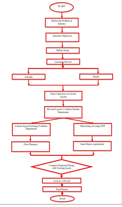
1.5 Case Study Methodology
The case study on facilities layout begins with identification of the problem, objectives and scope of project as illustrates in Figure 1.1. Basically, the problem statement of this case study is to optimize the flow distance in the Isuzu Company. Meanwhile, the objectives from this case study are to design a new layout that can improved space utilization of Isuzu Company and to select proper tool to solve facilities layout. The scope of the case study is limited to the data contained in the
Isuzu‘s layout. At the same time, this case study is only limited to a single
performance measure and only one method is used to solve the layout problems. After identifying the problem details, the technique and performance measure used
5
Current layout Existing (Combine Department
Revised Layout: Combine Similar Department
START
Define the Problem at Industry
Generate Objectives
Define Scope
Literature Review
Journals Books
Data Collection on Current Layout
Relocating out using GFP
Insert Space requirement Flow Distance
Compare Proposed Design with Existing layout
Analysis of Result
Final Report
STOP
6 1.7 Organization of Report
This report is meant for reporting activity for the Projek Sarjana Muda (PSM) I. The organization of this report has been constructed as followed:
1.7.1 Chapter 1
Chapter 1 presents the introduction of this case study. It covers the concept of facilities layout, problem statement, case study objectives, case study scope, and case study methodology. The concept of the facilities layout includes the definition of facilities layout, what the facilities layout used for, why we need the facility layout and the strength and drawbacks of facilities layout.
1.7.2 Chapter 2
Chapter 2 covers the review of literature. It includes the background of facilities layout, the needs for facilities layout, and literature review, which divided into method used and performance measure used.
1.7.3 Chapter 3
Chapter 3 explains on the methodology used for this case study. It describes the selection of tools or techniques suitable for facilities layout. In addition, this chapter also includes background of general flow pattern method, advantages and disadvantages this method, tool used in general flow pattern, developing a
7 1.7.4 Chapter 4
Chapter 4 shows the case study. Basically, this chapter provides introduction to Isuzu Company and presents the existing facilities layout as input data for this case study.
1.7.5 Chapter 5
Chapter 5 is presents the experimental design for General Flow Pattern in specific. In this chapter case study methodology in details are consist data collection, current layout for relevant departments, and also the step of general flow pattern may be proposed in facility layout.
1.7.6 Chapter 6
For this chapter are consist the result and discussion using GFP concept. It is represent flow distance travel for current layout and five of the layout proposed by using the GFP concept pattern.
1.7.7 Chapter 7
8
CHAPTER 2
LITERATURE REVIEW
Designing proper facilities layout is significant for manufacturing activities. A good facility layout may minimize movement, handling and travel distance. This minimization leads to shorter manufacturing lead time.
Due to the significant of facilities layout, this chapter laid foundation towards understanding the concept of facilities layout in section 2.1. Then, in section 2.2 describes the need for facility layout. Section 2.3 present, current scenarios in facilities layout case study before finely conclude the chapter in section 2.4.
2.1 Background on Facility Layout
Facility layout means planning for the location of all machines, utilities, employee workstations, customer service areas, material storage areas, aisles, restrooms,
lunchrooms, internal walls, offices, and computer rooms (IMEC, 2008). Apart from that, a facility planning is also used for organizing flow patterns of materials and people around, into and within buildings. The infrastructure services such as the delivery of line communications, energy, and water and the removal of waste water all make up basic utilities for facility layout. Most company applies this facility layout in their company to minimize movement, handling and travel distance of the material and labor while increasing overall productivity.
9
numerous strategic implications because it establishes an organization‘s competitive
priorities in regard to capacity, processes, flexibility and cost as well as quality of
work of life, customer contact and image. The effective layout helps organization in achieving better strategy to support differentiation, low cost or response. In this situation, facility layout strategy is to develop an effective and efficient layout that
will meet the firm‘s competitive requirements (Heizer and Barry, 2009, 2007, and
2005). In addition, a facility layout problem is also concerned with finding the most efficient arrangement of N indivisible departments with unequal area requirements within a facility (Castillo and Sim, 2003).
Fruggiero, Lambiase and Negri (2006) defined facility layout design (FLD) as concerned with the physical organization/allocation of a production system. In this facility layout problem, they determined criteria which maximize/minimize some objectives such as qualitative and quantitative liked production time, flexibility in volume and variety, allocation space, product quality and etc. The aim is to find the most efficient arrangement of M indivisible departments with unequal area requirement within a facility. In addition, plant layout process design is one of
industrial engineering‘s activities. Specifically, layouts are designed in such a way
that the activity of a fixed asset can give the best support in order to reach the objective of the activity.
2.2 The Need for Facility Layout