UNIVERSITI TEKNIKAL MALAYSIA MELAKA
FEEDRATES OPTIMIZATION AND IN BALL END MILLING
OF MILD STEEL
This report submitted in accordance with the requirements of the Universiti Teknikal Malaysia Melaka (UTeM) for the Bachelor Degree of Manufacturing Engineering
(Process) with Honours.
By
NOOR HAZNIL IKMAL BT ABDUL JALIL
FACULTY OF MANUFACTURING ENGINEERING
UNIVERSITI TEKNIKAL MALAYSIA MELAKA (UTeM)
BORANG PENGESAHAN STATUS LAPORAN PROJEK SARJANA MUDA
TAJUK:
Feedrates Optimization And In Ball End Milling Of Mild SteelSESI PENGAJIAN: 2009/2010 Semester 2
Saya NOOR HAZNIL IKMAL BT ABDUL JALIL
mengaku membenarkan Laporan PSM ini disimpan di Perpustakaan Universiti Teknikal Malaysia Melaka (UTeM) dengan syarat-syarat kegunaan seperti berikut:
1. Laporan PSM adalah hak milik Universiti Teknikal Malaysia Melaka dan Penulis. 2. Perpustakaan Universiti Teknikal Malaysia Melaka dibenarkan membuat salinan
untuk tujuan pengajian sahaja dengan izin penulis.
3. Perpustakaan dibenarkan membuat salinan laporan PSM ini sebagai bahan pertukaran antara institusi pengajian tinggi. atau kepentingan Malaysia yang termaktub di dalam AKTA RAHSIA RASMI 1972)
DECLARATION
I hereby, declared this report entitled “Feedrates Optimization In Ball End Milling Of Mild Steel” is the results of my own research except as cited in the references.
Signature : ………
APPROVAL
This report submitted to the Faculty of Manufacturing Engineering of UTeM as a partial fulfillment of the requirements for the degree of Bachelor of Manufacturing Engineering (Process) with Honours. The member of the supervisory committee is as follow:
………. EN. MOHAMAD RIDZUAN B JAMLI
ABSTRACT
ABSTRAK
DEDICATION
Special dedicated to my beloved mother, family, and friends who provide a loving,
caring, encouraging and supportive atmosphere. These are characteristic that
ACKNOWLEDGEMENT
First and foremost, thanks to ALLAH S.W.T for His blessings and strengths, I had finished this project. Next, I would like to place my gratitude to the ones that contributed to the success of this project. I wish to acknowledge and express my gratitude and appreciation to my supervisor, Mr. Mohamad Ridzuan bin Jamli for his supervision, encouragement, suggestion and assistance through the research.
Valuable suggestions, criticisms and comments have been made by numerous individuals. I greatly appreciate the time and effort the following people gave in order to complete my final year project and I really appreciate them for their help in improving the quality of this final year project:
TABLE OF CONTENT
2.2 Basic Concept of Feedrate Optimization 9
2.2.1 Comparison Between Pick-interval and Feed-interval Scallops 7
2.3 Tool Orientation 8
2.3.1 Effects of lead and tilt angles on the process 9
2.3.2 Regression Analysis 11
2.3.3 Determination of the Optimal Feedrate 11
2.4 The ‘f=p’ Machining 13
2.4.1 Effect Step over 13
2.5 Material and Tool material 15
2.5.1 Mild Steel 16
2.6 Other Parameters 20
2.6.1 Depth of Cut and Cutting Speed 20
2.6.2 Cutting Fluids in milling 24
2.7 Measurement 24
2.7.1 Portable Surface Roughness Tester 25
2.7.2 Maximum peak (Ry) 26
3.0 METHODOLOGY 27
3.1 Parameter Identification 27
3.1.1 Design of Experiment (DoE) 31
3.1.2 Calculation by Microsoft Excel 33
3.2 Machining 33
3.2.1 Material Preparation 34
3.2.2 Part Designing and Machining by CATIA software 35
3.2.3 Machine and Tools 37
4.4.1 Residuals versus Predicted Graph 45
4.4.2 Predicted versus Actual Graph 46
4.5 Model Graph 47
4.5.1 AB Interaction Graph 47
4.5.2 AC Interaction Graph 49
4.5.3 BC Interaction Graph 51
4.5.4 Cube Model graph 52
5.0 CONCLUSION AND RECOMMENDATION 55
5.1 Conclusion 56
REFERENCES
LIST OF TABLES
2.1 Cutting speeds for various materials 23
3.1 Illustrating Low and High Factor Values for DOE 32
3.2 Details of Parameters (a) 33
3.3 Details of Parameters (b) 33
3.4 Calculation by Microsoft Excel 34
3.5 Description of Tool 39
4.1 Result 42
LIST OF FIGURES
1.1 Ball-end milling cutter 2
1.2 Vertical path Strategy 3
2.1 Path Interval Scallop and Feed interval Scallop 9
2.2 Coordinate systems and lead–tilt angles. 10
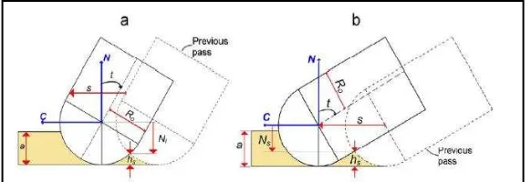
2.3 Scallop height : (a) s ≤ 2Ro cos t and (b) s ≥ 2Ro cos t 10
2.4 Surface Generated by Ball End Milling which Scallop Height, 14 Step Over is p and Feed per Tooth is f.
3.2 Process Squaring of Mild Steel 35
3.3 Design of the specimen 36
3.4 Drawing Projecting View 37
3.5 Surface to be machine 37
3.6 Haas Mini Mill Vertical Machining Centre 38
3.7 Process machining 38
3.8 Surface Roughness Measurement 40
4.1 Half Normal Plot 44
4.2 Residuals versus Predicted Graph 45
4.3 Predicted versus Actual Graph 46
4.4 AB Interaction Graph 47
4.5 AB 3D-Interaction Graph 47
4.6 AC Interaction Graph 49
4.7 AC 3D-interction Graph 50
4.8 BC Interaction Graph 50
4.10 Overall Data in Cube View 52
4.11 Continuous chips 53
LIST OF ABBREVIATIONS
C - Cross Feed Vector
CAD - Computer Aided Dimension
CATIA - Computer Aided Three-dimensional Interactive Application CNC - Computer Numerical control
CMOS - Complementary Metal-Oxide Semiconductor DOE - Design of experiment
F - Feed Vector
HSS - High Speed Steel
NC - Numerical Control
PH - Parker-Hannifin Corporation (NYSE) PCD - Polycrystalline diamond
Ra - Arithmetical Roughness
Ry - Maximum Height
Rz - Roughness
Sm - Spacing of Profile Irregularities SPC - Statistical Process Control
tp - Ratio
CHAPTER 1
INTRODUCTION
The content of this chapter is introduction to Ball End Mill. Here, the definition is explained as the movement of ball end milling and the result of scallop-height after machining. The problem statement, objectives of the project, scope of study and finally the contents of dissertation conclude this chapter.
1.1 Introduction to Ball End Mill
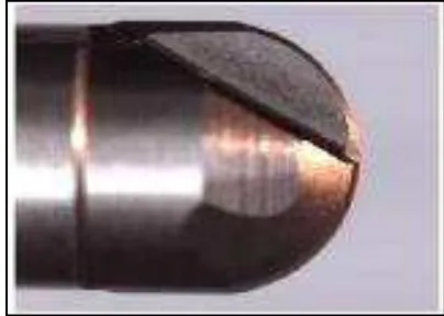
A ball end mill is suitable to milling many types of materials, from plastics to steel alloys and titanium. The toughness and durability of the cutting edge is very high in Ball End Mills because of the rounded edge design. This fact is actually just a by product of the rounded cutting edge. It was rounded for a specialized purpose, often for milling grooves with a semi-circular cross-section. This type of groove is an important part of the metal bearings used in many machines.
Figure 1.1: Ball-end milling cutter (Jin, et al ,2007)
Tool path generation is the main issue in the finishing stage of NC machining. In order to satisfy surface finish quality, tool paths are generated so that the scallop height formed by two adjacent tool paths is controlled within a predefined machining tolerance. In order to fill this requirement, the path interval should be small enough, and consequently, the machining efficiency is limited. To achieve a significant improvement in machining efficiency, the scallop height is kept at a constant which is equal to the predefined machining tolerance. ( Yoon, 2005)
Ball end mills are usually made from tungsten carbide and a high-strength metallic compound containing tungsten and carbon. The powder of tungsten carbide is pressed into rods, which are then ground and sharpened to various specifications. Usually, a typical ball end mill is manufactured with a protective coating which the coatings are comprise titanium mixed with other elements such as carbon and aluminium.
Finding optimum machining parameters in 3D sculptured surface machining is quite a widely researched problem. The cutting force generated during machining process is an important parameter, which reflects the machining conditions. The other important factors for the optimum machining are cutting time, cutting tool cost, quality of surface achieved, and machining errors visualized as shape deviation from the ideal. The above mentioned issues should really be considered simultaneously, which would render the optimization problem quite intricate. With an on-line monitoring system, the machining process and above mentioned factors can be monitored easily.
The determination of efficient cutting parameters has been a problem confronting manufacturing industries for nearly a century, and is still the subject of many studies. To ensure the quality of machining products, and to reduce the machining costs and increase the machining effectiveness, it is very important to select the optimal machining parameters. Optimal machining parameters are of great concern in manufacturing environments, where economy of machining operation plays a key role in the competitive market.
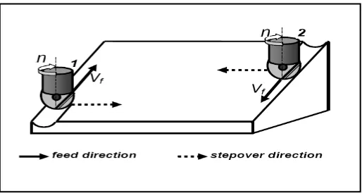
The cutter path orientation is crucial in achieving desired machined surface and without considering the impact of cutting edge with undeformed chip in different path strategy with adequate consideration of the chip area variation, cutting forces, temperature and vibration analysis, the result can lead to cutter failure and therefore lead to unnecessary waste of time, cost and poor surface quality In this report the vertical path strategy, in climb-milling (feed and cutting speeds are in the same sense, tool-left in CNC program) is evaluated using 3D-CAD geometric method and according to the feed direction the milling can be divided to vertical upward and vertical downward(Fig.1.2): (Cosma, 2005)
This project investigated the feedrate optimization and efficiency enhancement in Ball End Milling on Mild Steel process because the previous works show that it is the one of factor that affects the feed-interval scallop due to the dynamical and the periodical change of the cutting edge orientation. In addition, this project also investigate the calculation of „f=p‟ by Chen, (2005) that refer to the path and pick interval scallop produced after machining. Also, in other parameters in ball end milling that will be considered in this project is depth of cut, lubrication, material and tool material.
1.2 Problems statement
In this project, the scallop heights generate by ball end milling machining are depends on the design desired. But, the way to enhance the efficiency in the Ball End Milling machining, variable feedrates optimization instead of constant feedrate becomes very important under constraints of surface roughness and the generated scallop height. In addition, the study of optimization of the feedrate will be consider the generated-scallop effect by the ball-end cutter.
In this project, the sweeping process will be use to see the result or the surface generated.
1.3 Objective
a) The objective of this project is to study the optimization of the feedrate in Ball End Mill in order to consider the generated-scallop effect by the ball-end cutter.
b) To optimum quality and efficiency in order to improve scallop height of machining in ball end milling.
c) To obtain the scallop height after done isoparametric process in ball end milling process by using 3-axis CNC milling machine.
1.4 Scope
This study is mainly about the experimental test of the Ball end milling process to study the effects of the feedrate of Ball End Milling process on the mild steel. The focus of this project is study on the several journals to identify the method to calculate the feed interval scallop. By this, the generated-scallop will be measure using the calculation to compare the better surface roughness due to the variable feedrate optimization using measuring scope. Different feedrates of the Ball end milling machine will result different surface roughness.
CHAPTER 2
LITERATURE REVIEW
This chapter consists of literature reviews of subjects that are going to be investigated throughout this project. Theories, related studies, testing involve and previous researches of the feedrate optimization in ball end mill and matters involved will be reviewed. The concept of sculptured surface including feedrate especially with calculation that related to the process also step over distance, tilt and lead angles, cutting speed, spindle speed and depth of cut. Previous research from journals and papers are also being reviewed. This is to ensure that the project will be guided and avoid mistakes once the experiment takes place.
2.1 Introduction
2.2 Basic Concept of Feedrate Optimization
To make the machining safe and efficience, the most important factor is feedrate. Feedrate is the rate at which the material is advanced into the work material. Depending on the rate of feed, a chip on a given thickness will be removed since each tooth of a multitooth milling cutter is cutting (Chen, et al., 2005). To give the longest tool life between resharpenings, they must be highest practical feed per tooth. From the machining of the ball end millng, the first thing that important to understanding is differential between pick-interval and feed-interval scallops.
In ball end milling operations, the cutting tool must step over and make several adjacent cuts to complete machining a feature. As a result, a small cusp of material, called a scallop, will remain between these cuts on any surrounding walls or on the machined surface if a ball end mill is used. The size of the step-over distance and the tool diameter will determine the scallop height between each step. Decreasing the step-over distance will minimize the scallop height, but will require more steps, and therefore more time, to machine the feature.
2.2.1 Comparison between Pick-interval and Feed-interval Scallops
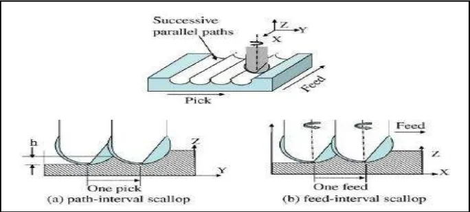
Figure 2.1: Path Interval Scallop and Feed interval Scallop (Chen, et al., 2005)
When the ball-end milling proceeds along a cutting path, the orientation of the cutting edge is dynamically and periodically changed during the spindle rotation. Due to the spherical shape of the ball-end cutter, another kind of feed-interval scallop is generated between successive tooth feeds. At the first look, the shape and generating mechanism of the feed interval scallop looks exactly same as the path-interval scallop.
The distance between two adjacent tool paths is commonly referred as side step or tool path interval. Generally the scallop-height requirement is employed to control the side steps of CNC tool paths (Yang, 2008).
2.3 Tool Orientation
Figure 2.2: Coordinate systems and lead–tilt angles (Ozturk, E , et al., 2009)
The tool tilt angle is defined as the angle of rotation between the centerline of the tool and the normal plane to the workpiece. Contact angle is defined as the total angle of contact of the tool flute that is in contact with the workpiece and is a function of depth of cut. Since ball-ended mills are used in this research, the contact angle will always be the angle from workpiece normal to the workpiece surface.
2.3.1 Effects of lead and tilt angles on the process
Lead and tilt angles have effects on different factors such as tool tip contact with the workpiece, scallop height, cutting forces, torque, form errors and stability. In 5-axis milling, the additional motions of the cutter are the two rotary axes. (Ozturk, et al. ,2009)