AdAptive GAin Controller UsinG Model
referenCe AdAptive Control Method stAbility
ApproACh for roAd vehiCle followinG systeM
M. r. sapiee1, A. noordin1
1Faculty of Electrical Engineering, Universiti Teknikal Malaysia Melaka, Locked Bag 1752, Pejabat Pos Durian Tunggal,
76109 Durian Tunggal, Melaka.
Email: 1[email protected]
ABSTRACT
In order to maintain stability and satisfy operating constraints, the control system on the following vehicle needs information about the motion of preceding vehicle. A one-vehicle look-ahead control strategy is proposed and will be investigated for this operation. A mathematical model for this control strategy is obtained and simulated. This paper describes the process of designing an adaptive gain controller for a road vehicle following
system. This is done through simulations and is further discussed to ind the efectiveness of the method.
KEYWORDS: One-vehicle look-ahead control, model reference adaptive control, stability approach.
1.0 introdUCtion
In general, Malaysian drivers tend to follow another vehicle closely. Hence, platoons or convoys appeared to develop rapidly. This normally happens when spacing between vehicles is close and there is no chance for the following vehicle to overtake the preceding vehicle. The vehicle at the back or the following vehicle will have to adjust its speed and spacing with respect to the preceding vehicle. If this is not taken into careful consideration, collision between them may occur.
ISSN: 2180-1053 Vol. 2 No. 1 January-June 2010 56
have a nominal speed and a safe distance between his vehicle and the preceding vehicle.
Nowadays, all the information does not need to be estimated. Sensors are available to measure the speed of the preceding vehicle and the position of the preceding vehicle with respect to the following vehicle. The information from the sensors will be used and processed by the following vehicle controller to produce the required speed and the safe spacing distance.
This is where autonomous control can take place. The controller can automatically ensure safe distance based on the information obtained from the preceding vehicle. The autonomous controller on the following vehicle can activate the vehicle cruise control mode, where the driver does not need to hold the steering nor press the fuel pedal, and automatically apply the brake when necessary in order to ensure the safety of the vehicle.
In developed nations, the autonomous concept leads to the Intelligent Vehicle Highway System (IVHS). As a vehicle enters the highway, his vehicle automatically takes-over the control of the vehicle while following the preceding vehicle. This feature also gives rise to steering less technology where during the autonomous control in action, the driver does not need to hold the steering wheel. All the driving tasks are taken care by the vehicle intelligent system.
One of the autonomous features is the adaptive type control based on certain control strategy which gives rise to Adaptive Cruise Control (ACC). An ACC controlled vehicle will follow the front vehicle at a safe distance. A Model Reference Adaptive Control (MRAC) can be used in this type of control where the vehicle controller has the ability to adapt to the variation of speed and position of the preceding vehicle.
2.0 one-vehiCle looK-AheAd Control strAteGy
following vehicle front vehicle FIGURE 1
A vehicle following system
The following vehicle can be controlled in such a way that it will maintain either the same speed to that of the immediate preceding vehicle, which is the front vehicle or maintain a safe distance in order to avoid collision between them. This is where the string stability plays an important role by having a string stable vehicle following system. The system is said to be stable if the range errors decrease as they propagate along the vehicle stream.
In this control strategy, the controlled vehicle only refers the information from the preceding vehicle. So, the control system on the following vehicle needs information about the motion of preceding vehicles. Yanakiev, D. and Kanellakopoulos, I. used a simple spring-mass-damper system to demonstrate the idea of string stability and show the string-stability criterion for constant headway and variable time-headway policies. A mathematical modeling for this control strategy is shown in Figure 2 where i denotes the following vehicle and i-1 denotes the preceding vehicle.
Mathematical model of a vehicle following system control strategy
Performing the mathematical modelling on only the following vehicle
ISSN: 2180-1053 Vol. 2 No. 1 January-June 2010 58
The transfer function in Equation (2) depends on the following spacing policy.
The aim of this strategy is to maintain string stability for longitudinal motion within the vehicle following system or the vehicle convoy, particularly between a vehicle with a vehicle or between a vehicle with a following vehicle. This strategy is adopted in order to design a controller by investigating the following two policies.
2.1 spacing policy
Researchers are trying to get close inter-vehicular spacing between
vehicles, in order to have an efective following system. Spacing policy is deined as a rule that dictates how the speed of an automatically
controlled vehicle must regulate as a function of the following distance. A control system should be designed such that it regulates the vehicle speed according to the designed spacing policy.
There are three basic spacing policies employed by many researchers
thus far. Those spacing policies are the ixed spacing policy, the constant time headway policy and the variable time policy. Only the irst two
will be discussed and investigated in this paper.
2.1.1 fixed spacing policy
Under this policy, a ixed inter-vehicular spacing is implemented
regardless of the vehicle’s speed. A well-known result states that it is impossible to achieve string stability in an autonomous operation when this spacing policy is adopted. This is mainly due to the relative
spacing error that does not atenuate as it propagates down the string at all frequencies. Spacing error atenuation will only occur for frequencies above certain level. In addition, keeping the same ixed spacing at diferent convoy speed would risk the safety and comfort of
passengers, especially when the vehicles are closely separated.
Obviously, at higher speed, faster vehicle reaction time is needed in an
emergency situation to avoid collision. Nevertheless, the ixed spacing
vehicle having sensors to detect the above two parameters. Equation
(2) shown before is the transfer function for the ixed spacing policy.
2.1.2 fixed headway spacing policy
This spacing policy keeps a ixed time interval, called time headway or
headway, h, between the preceding vehicle and the following vehicle. It is a speed dependent policy where the inter-vehicular spacing will vary according to the preceding vehicle speed. At higher speed, vehicles will
be separated in a greater distance but always maintains a ixed time
interval between vehicles. Most researchers used this spacing policy in designing controllers to ensure string stability as this policy mimics the behavior of human drivers. As vehicle speed is increased, a human driver will keep a safe inter-vehicular spacing with the immediate preceding vehicle.
The performance of the ixed headway spacing policy used in
autonomous and cooperative vehicles following systems has been
studied. It is found that there exists minimum possible ixed headway
spacing before the string stability of a convoy collapses which is related
to the actual dynamics of the vehicle. The efect of this ixed headway
spacing policy is equivalent to the introduction of additional damping in the transfer function, which allows the poles of the transfer function to be moved independently from the zeros of the same transfer function.
With the addition of the ixed headway spacing, Equation (2) then
becomes
with the control law developed as
ISSN: 2180-1053 Vol. 2 No. 1 January-June 2010 60
Thus,
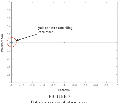
Figure 3 shows the pole-zero maps with pole and zero cancelling each other. Through the pole-zero cancellation technique, Equation (3) is thus reduced to
which is a irst order transfer function with a stable response with time delay. While kv must always be positive, there exists a pole which is always in the let hand side of the s-plane. Thus, the system is always
stable for this spacing policy.
u
pole and zero cancelling each other
FIGURE 3
Pole-zero cancellation map
2.2 Inclusion of Vehicle Dynamics
Ater proving that the ixed time headway policy is suitable to be adopted, a simpliied vehicle dynamics model is introduced in order to mimic the actual vehicle internal dynamics. In this case, the external dynamics is not considered. In the simpliied model, the internal
dynamics is represented as a lag function i.e., the actual vehicle
Equation (3) is modiied to include the vehicle dynamics part and this
gives a transfer function in Equation (9).
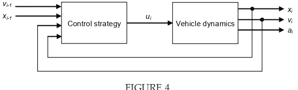
Having designed the control strategy and by including the vehicle dynamics, the block diagram of the one-vehicle look-ahead vehicle following system is shown in Figure 4.
Control strategy Vehicle dynamics
vi-1
ai vi xi ui
xi-1
FIGURE 4
Block diagram consisting of the control strategy and vehicle dynamics
If τ is so small (as in an ideal vehicle) i.e. , then . Hence, the transfer function is reduced back to a second order transfer function.
ISSN: 2180-1053 Vol. 2 No. 1 January-June 2010 62
FIGURE 5
Speed response of ixed headway with various kp values
FIGURE 6
Acceleration response of ixed headway with various kp values
3.0 Model referenCe AdAptive Control
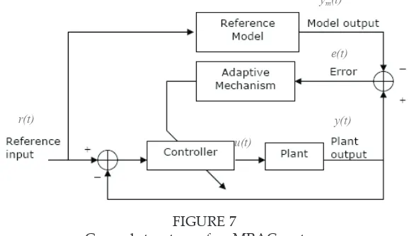
feedback loop with plant and controller and an adaptive parameter mechanism loop. Figure 7 illustrates the general structure of a Model Reference Adaptive Control (MRAC) system.
FIGURE 7
e(t) ym(t)
y(t)
u(t) r(t)
FIGURE 7
General structure of an MRAC system
The basic MRAC system consists of four main components:
i) Plant to be controlled
ii) Reference model to generate desired closed loop output response
iii) Controller that is time-varying and whose coeicients are
adjusted by adaptive mechanism
iv) Adaptive mechanism that uses ‘error’ (the diference
between the plants and the desired model output) to
produce controller coeicient
Regardless of the actual process parameters, adaptation in MRAC takes
the form of adjustment of some or all of the controller coeicients so as
to force the response of the resulting closed-loop control system to that of the reference model. Therefore, the actual parameter values of the
controlled system do not really mater.
3.1 the stability Approach
The MRAC can be designed such that the globally asymptotic stability
ISSN: 2180-1053 Vol. 2 No. 1 January-June 2010 64
also known as the Lyapunov Approach.
In designing the MRAC controller, we would like the output of the closed-loop system (y) to follow the output of the reference model (ym). Therefore, we aim to minimise the error (e=y-ym) by designing a controller that has one or more adjustable parameters such that a certain cost function is minimized.
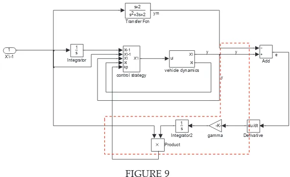
4.0 AdAptive GAin Controller desiGn
An adaptive gain controller is to be designed for the one-vehicle
look-ahead control strategy with ixed time headway and vehicle dynamics
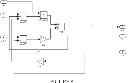
by applying a Model Reference Adaptive Control (MRAC). This section presents a direct adaptive controller design which adapts the unknown vehicle parameter kp. The advantage of the adaptive approach is that unpredictable changes in the value of kp can be easily accommodated. Figure 8 on the other hand shows the one-vehicle look-ahead control strategy based controller with the gain parameter to be adjusted, kp is the gain adjustment mechanism to be designed in the control strategy.
FIGURE 8
A one-vehicle look-ahead controller with adjustable gain
4.1 the stability Approach design
From the analysis of Figure 6, kp value of 2 gives the best response. So, it will be used in Equation (10) to give a reference model to be used in designing the adaptive gain controller. The vehicle dynamic has been included in the control law to form the plant.
Reference model:
A closed-loop system with a controller has the following parameters:
r(t) = Reference input signal
u(t) = Control signal
y(t) = Plant output
ym(t) = Reference model output
e(t) = Diference between plant and reference
model output = y(t) - ym(t)
In designing an MRAC using stability approach, the following steps should be followed:
i) Derive a diferential equation for error, e = y − ym that
contains the adjustable parameter, . From Equations (11) and (12), ater replacing, the diferential equation becomes
Substituting equations (13) and (14) into , thus
ISSN: 2180-1053 Vol. 2 No. 1 January-June 2010 66
The Lyapunov function, , is based on Equation (16). , where is positive deinite. The derivative of V becomes
where for stability must be negative i.e. .
iii) Derive an adaptation mechanism based on such that e goes to zero.
Therefore,
The block diagram implementation is given in Figure 9 where is
denoted by gamma in the simulation diagram and the red doted line
is the adaptive mechanism.
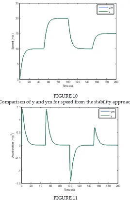
The stability approach adaptive gain controller simulation diagram.
follow a sharp change in input acceleration.
Comparison of y and ym for speed from the stability approach
FIGURE 11
Comparison of y and ym for acceleration from the stability approach
ISSN: 2180-1053 Vol. 2 No. 1 January-June 2010
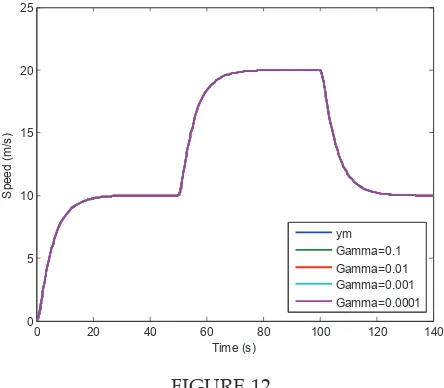
Speed response with various gamma values for adaptive gain controller
FIGURE 12
Acceleration response with various gamma values for adaptive gain controller
Shown in Figure 12 and Figure 13 are the speed and acceleration responses for the adaptive gain controller, respectively. Further analysis of Figure 13 gamma value of between 0.01 and 0.001 gives the best
response by almost iting the reference model with smooth curve and
with jerk of less than 5 m/s3.
A one-vehicle look-ahead control strategy with ixed headway policy
is the speed with varying speed conditions. With normal controller, the response does not quite match perfectly with the input. With the introduction of the MRAC adaptive gain controller, the response can be made to follow the input by choosing a suitable reference model. Furthermore, using MRAC adaptive gain controller produces a smooth output as compared to the other one.
5.0 ConClUsion
The adaptive gain controller tuning has been investigated using MRAC concepts through the stability approach. Simple adaptation law for the controller parameters has been presented assuming that the process
under control can be approximated by a second order transfer function.
The developed adaptation rule has been applied and simulated. The
results obtained show the efectiveness of the technique. The resulting performance could be improved by a beter choice of the length of the
adaptation period.
The stability approach is used to provide guaranteed nominal stability. However, the stability approach controller can only have very small
gain with 1 is the maximum limit.
A further limitation of the approach is the assumption of a structure for the nominal system. In this paper, a second order transfer function has been assumed resulting from the assumption of a very small time delay between the command signal and the vehicle dynamics as in ideal vehicle.
6.0 ACKnowledGMents
The authors would like to acknowledge their gratitude to Faculty of Electrical Engineering, Universiti Teknikal Malaysia Melaka for providing the resources and support in the completion of this paper.
ISSN: 2180-1053 Vol. 2 No. 1 January-June 2010 70
Liang C. Y. and Peng H. (1999). Optimal Adaptive Cruise Control with Guaranteed String Stability’. Vehicle System Dynamics. Volume 31. pp 313-330.
M. R. Sapiee, H. Selamat, A. Noordin, A. N. Jahari (2008). PI Controller Design Using Model Reference Adaptive Control Approaches For A Chemical Process. Proceedings of 2008 Student Conference on Research and Development (SCOReD 2008). 26-27 Nov. 2008. pp. 155-1 to 155-4.
P.A. Cook and S. Sudin. (2003). Convoy dynamics with bidirectional low
of control information. 10th, IFAC Symposium on Control in Transportation Systems, Tokyo, Japan. 4-6 August 2003. pp. 433-438.
P.A. Cook and S. Sudin. (2002). Dynamics of convoy control systems. 10th IEEE Mediterranean Conference on Control and Automation, Lisbon, Portugal. 9-12 July 2002. WP7-2.
S. Sudin and P.A. Cook. (2003). Dynamics of convoy control systems with two-vehicle look-ahead strategy. International Conference on Robotics, Vision, Information and Signal Processing, Universiti Sains Malaysia, Penang, Malaysia. 22-24 January 2003. pp. 327-332.
S. Sudin and P.A. Cook. (2004). Two-vehicle look-ahead convoy control systems. 59th, IEEE Vehicular Technology Conference, Milan, Italy. 17-19 May 2004. Volume 5. pp. 2935-2939.
S. Sudin (2005). Dynamics and control of vehicle convoy systems. PhD Thesis. School of Electrical and Electronic Engineering, Faculty of Engineering and Physical Sciences, The University of Manchester.
Yanakiev, D. and Kanellakopoulos, I. (1996). A Simpliied Framework for String