i
APPROVAL
“I hereby declare that I have read this thesis and in my opinion this thesis is sufficient in term of scope and quality for the award of Bachelor of Mechanical
Engineering (Design & innovation)”
ii
DECLARATION
“I hereby, declare this thesis is result of my own research except as cited in the references”
Signature : ………..
iii
DEDICATION
Special Dedication to my family members, my friends,
my fellow colleague and all faculty members for all your
iv
ACKNOWLEDGEMENT
First of all, I would like to thanks Gods that have given me the opportunity to
complete my ‘Project Sarjana Muda’ (PSM). Alhamdulillah, His Willingness has made it
possible for me as the author to complete the PSM in time. I worked hard in completing this
project within a semester.
I would like to take this opportunity to give my special thanks to my dedicated
previous supervisor, Associate Professor Ir. Mustafar Bin Ab Kadir and also my new
supervisor Professor Dr. Md.Razali Bin Ayob for guiding this project at every stage with
clarity, spending much time to discuss and help with this project, and that priceless gift of
getting things done by sharing his valuable ideas as well as share his knowledge. I would also
like to thank to all UTeM lecturers whom had helped directly or indirectly in what so ever
manner thus making this PSM a reality.
Not forgotten are my best colleagues for their openhandedly and kindly guided,
assisted, supported and encouraged me to make this project successful. My heartfelt thanks to
my dearest family which always support and pray on me throughout this project. Their
blessing gave me the high-spirit and strength to face any problem occurred and to overcome
them rightly.
The great cooperation, kind heartedness and readiness to share worth experiences that
v
ABSTRACT
The air conditioner is a medium to get an environment pleasant reply. The air
condition will generate cool air to the environment such as in homes, offices and building.
There are different types of air conditioner such as window unit air conditioner, split unit,
ducted unit and the package unit. Air conditioners require energy to produce a cool effect on
the environment. Solar energy can also be used to produce that cool effect . The use of solar
energy at present is very broad. The electricity consumption can be saved using solar energy.
Solar energy used for air-conditioning is to act as a medium of hot water production which
can be used to respond with refrigerant to produce cool air. To get hot water, solar evacuated
tubes were used for concentration of sunlight energy. Water in the solar evacuated tube will
be heated by the sun. This research is focused on the solar system reaction with the air
conditioning system. This study also identified a system that has been used to produce the
effect of cold air with the aid of solar energy. Factors had been taken into this study is to
calculate the number of sets of Solar Evacuated Tube which is needed for cooling the main
vi
ABSTRAK
Penyaman udara merupakan satu medium untuk mendapatkan keadaan persekitaran
yang sejuk dan nyaman. Penyaman udara akan menghasilkan udara sejuk kepada persekitaran
seperti di dalam rumah, pejabat dan juga banggunan. Terdapat berbagai jenis penyaman udara
iaitu jenis tingkap, jenis berasingan, jenis berasingan bersesalur dan juga jenis kemas siap.
Penyaman udara memerlukan tenaga elektrik untuk menghasilkan kesan sejuk pada
persekitaran. Tenaga solar juga boleh digunakan untuk menghasilkan kesan sejuk pada
system penghawa dingin. Penggunaan tenaga solar pada masa kini adalah sangat meluas.
Penggunaan tenaga solar dapat menjimatkan penggunaan tenaga elektrik. Tenaga solar yang
digunakan untuk penyaman udara adalah bertindak sebagai medium penghasilan air panas
yang boleh digunakan untuk bertindak balas dengan bahan penyejuk supaya dapat
mengasilkan udara sejuk. Untuk mendapatkan air panas, alat salur paip penumpu matahari
digunakan bagi tujuan penumpuan cahaya matahari. Air yang berada di dalam paip tersebut
akan dipanaskan oleh cahaya matahari. Kajian yang dijalankan ini memberi tumpuan kepada
sistem solar yang dapat bertindak balas dengan sistem penyaman udara. Kajian ini juga
mengenal pasti sistem yang telah digunakan untuk menghasilkan kesan udara sejuk dengan
bantuan tenaga solar. Faktor yang diambil kira dalam kajian ini ialah bilangan set ‘Solar
Evacuated Tube’ yang diperlukan untuk proses penyejukan dewan besar Universiti Teknikal
vii
2.2.1.1Mechanical Air Conditioning and Ventilation 8
2.2.1.2Split Unit Air Conditioning 9
2.2.2 Split Unit Flow rate 10
2.2.3 Air Change per Hour (ACH) 11
2.3 Solar Air Condition 11
2.3.1 Solar Cooling Technology 12
2.3.2 Components of a solar cooling system 12
2.4 Solar Water Heater 12
2.5 Types of solar collectors 13
viii
2.5.1.1 Liquid collectors 14
2.5.1.2 Air Collector 15
2.6 Evacuated tube collectors 16
2.6.1 Glass Evacuated tubes 17
2.7 Benefit of the solar water heater 17
2.8 Solar boosting panel 18
2.9 Cooling tower 19
2.9.1 Cooling Tower Design 21
2.10 Absorption Chillers 22
2.10.1 Absorption Chiller Energy Efficiency 23
2.10.2 Lithium bromide/water cycle machines 25
2.11 Market potential for the solar air conditioning 26
2.12 Green Technology 27
CHAPTER 3 3.0 METHODOLOGY 29
3.1 Identify problem statement, objective and scope 30
3.2 Literature review 31
3.3 System Definition 31
3.4 Parameter for the system 31
3.4.1 Site Study 31
3.4.1.1Solar Evacuated Tube Temperature 33
3.4.2 Advantages 34
3.4.2.1 Benefits of Using Solar Air-Conditioning 35
3.4.3 Efficiency 36
3.4.4 Engineering Hardware 38
3.4.5 Design Theory 40
3.4.2.1 Absorption chillers process flow 41
CHAPTER 4 4.0 RESULT 43
4.1 Number of tube required 43
4.2 Price 49
CHAPTER 5 5.0 DISCUSSION 50
CHAPTER 6 6.0 CONCUSION AND RECOMMENDATIONS 52
6.1 Conclusion 52
6.2 Recommendations 53
ix
BIBLIOGRAPHY 56
x
LIST OF FIGURE
FIGURE PAGE
Figure 1: Air condition diagram 3
Figure 2: The diagram for air conditioning process 4
Figure 3: Condenser 5
Figure 4: Expansion Device 7
Figure 5: Evaporator 7
Figure 6: Z array collector 14
Figure 7: U array collector 14
Figure 8: Solar air collector 15
Figure 9: Evacuated tube collector 16
Figure 10: Glass Evacuated Tubes 17
Figure 11: Solar Boosting Panel 18
Figure 12: Cooling Tower 19
Figure 13: Basic process scheme of thermally driven chillers 20
Figure 14: Schematic overview of a generic cooling tower flow 22
Figure 15: Chillers 23
Figure 16: Principle of absorption chillers 23
Figure 17: Diagram of two-shell lithium bromide cycle water chillers. 25
Figure 18: Annual sales room air conditioner (RAC) 27
Figure 19: Process flow chart 30
Figure 20: Schematic diagram of the Solar Air condition system 32
Figure 21: The solar evacuated tube was located at the roof with temperature multi
meter. 33
Figure 22: The temperature after 15 minutes, 97°C 34
Figure 23: Overview of absorption cooling and electrical cooling 38
Figure 24: Schematic Building Automation system 39
Figure 26: Simple graphic from solar district cooling 40
xi
Figure 28: Solar evacuated tube seido 1-16 45
Figure 29: The area of the solar evacuated tubes 47
Figure 30: Sample of arrangement of 8set solar evacuated tube. 48
Figure 31: The arrangement of the solar evacuated set. 48
Figure 32: Roadmap for Solar Cooling (Source: Solar district cooling) 49
xii
LIST OF TABLE
TABLE PAGE
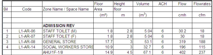
Table 1: Split unit flow rate schedule 10
Table 1: COP Absorption chillers 24
Table 3: Annual Electricity Saving 35
Table 4: Electricity Consumption for Conventional Air conditioning System 36
Table 5: Electricity Consumption for Solar Air Conditioning System 37
Table 6: Schedule of the Chiller 44
1
CHAPTER 1
INTRODUCTION
Air conditioning that powered by solar energy has great potential in the cooling
system design nowadays. It is because of high demand for cooling usually
coincides with plentiful sunlight. Solar air conditioning at an economically
competitive level could reduce electricity costs for residential and small
commercial customers. This would cut the growth of peak electric demand and
ease the increasing pressures on generating capacity, transmission, and
distribution. Currently available technologies are neither practical nor
cost-effective. Photovoltaic (PV) systems require a large roof area and cost many
times more than a conventional air conditioner. Thermally driven absorption
cooling requires costly, high-temperature collectors and undesirable cooling
towers. Furthermore, these systems have a disconnect of several hours between
peak cooling capacity and peak cooling demand. That in turn requires electric or
thermal storage in order to maximize the solar contribution. A solar
air-conditioning system employing relatively inexpensive low-temperature
collectors, coupled with an innovative desiccant dehumidification and
evaporative process, provides a new prospect for cost-effective solar cooling.
Solar cooling technologies use solar thermal energy provided through solar
collectors to power thermally driven cooling machines. Cooling demand is
rapidly increasing in many parts of the world, especially in moderate climates,
such as in most EU member states. This results in a dramatic increase in
electricity demand on hot summer days, which causes an unwanted increase in
the use of fossil and nuclear energy and furthermore threatens the stability of
electricity grids. As many cooling applications, such as air conditioning, have a
2 solar thermal and cooling obviously has a high potential to replace conventional
cooling machines based on electricity. Larger solar cooling systems have been
successfully demonstrated and smaller machines, which could be used in (small)
residential and office buildings, are entering the market.
1.1 Objective
The main objective of this project are to do the feasibility study in applying
the solar absorption system in the cooling system at the Univertiti Teknikal Malaysia
Melaka (UTeM) main hall and establish the number of set solar evacuated tube panel
required for the air conditioning by using absorption system.
1.2 Problem Statement
The uses of air condition are widely, air condition is very important for the
people because it can make a better environment for the people. Nowadays the
temperature of the earth is increasing. That why the air condition is very important.
But the uses of the air condition will increase the uses of electrical energy. To settle
this problem, this research will come out to decreasing the uses of the electrical
energy. The concept of this air condition is use a solar energy to produce a hot water
that can transfer to the air condition and will generate the cold air. The hot water
helps to produce a cold air by using the absorption chillers and cooling tower.
1.3 Scope
This work will limit itself to the study of solar cooling. The absorption refrigerant
system is studied where the heat for the generator is supplied by solar energy. Design
for the use of commercialized Solar evacuated tube is made to be applied to the
3
CHAPTER 2
LITERATURE REVIEW
2.1 Air conditioning
An air conditioner is an appliance, system, or machine designed to stabilise
the air temperature and humidity within an area typically using a refrigeration cycle
but sometimes using evaporation, commonly for comfort cooling in buildings and
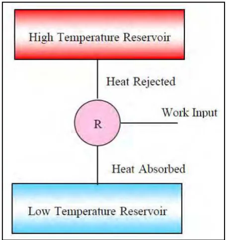
motor vehicles. The air conditioning system transfers heat from a cooler low-energy
reservoir to a warmer high-energy reservoir. (Laurie Mcguire 2003)
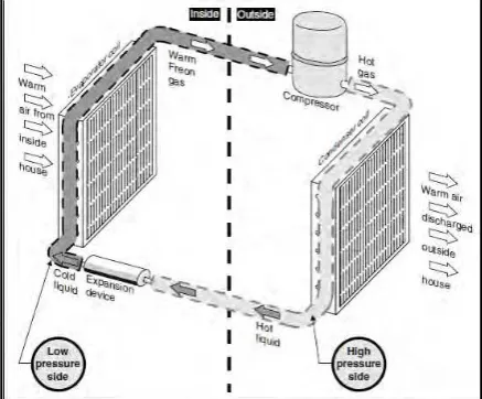
4 Basically air conditioning system has four components. The first component in the
air condition cycle is the compressor. The compressor takes low temperature
refrigerant gas and compresses it into a high pressure, high temperature gas. The
refrigerant is then sent to the condenser which sits in front of the radiator. The
condenser removes some of the heat from the refrigerant which causes the refrigerant
to change phase from a hot gas to a warm liquid. In the expansion valve air condition system, the warm liquid is then passed through a receiver-drier which removes moisture
from the refrigerant to maximize the efficiency of the heat exchange capability of the
refrigerant.From there, the refrigerant is then passed through the expansion valve.
Figure 2: The diagram for air conditioning process
(Source: principle of air conditioning)
2.1.1 Compressor
The heart of the vapour compression cycle is the compressor. The four most
common types of the refrigerant compressor are the reciprocating, screw, centrifugal
and vane. The reciprocating compressor consists of a piston moving back and forth
in a cylinder with suction and discharger valves to allow pumping to take place. The
screw, centrifugal and vane compressors all use rotating elements, the screw and
vane compressors are positive-displacement machine, and the centrifugal compressor
5
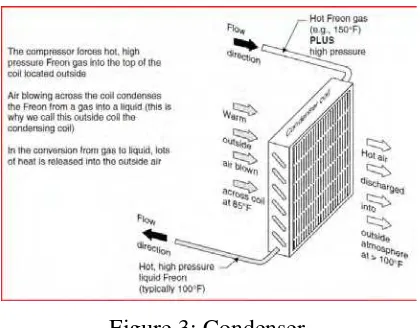
2.1.2 Condensers
The type of a condenser is generally characterized by the cooling medium used.
Thus, there are three types of condensers:
a) Air cooled condenser
b) Water cooled condenser
c) Evaporative condenser
Figure 3: Condenser
(Source: principle of air conditioning)
a) Air cooled condenser
In air cooled condenser, heat is removed by air using forced circulation or by
either natural. The condensers are made from steel, cooper or aluminium
tubing provided with fins to improve air-side heat transfer. The refrigerant
flows inside the tubes and the air outside.
b) Water cooled condensers
Water cooled condenser can be of three types, it is shell and tubes,
shell and coil, and double tube. The shell and tubes type, with water flowing
through passes insides tube and the refrigerant condensing in the shell is most
commonly used condenser. Figure shows the arrangement for a two pass
condenser. A shell and tube condenser also serves the purpose of a receiver
6 in the shell. The bottom portion of the condenser also serves the purpose of a
sub cooled as the condenser liquid comes in contact with the entering water at
a lower temperature. (Arora CP 2001)
c) Evaporative Condenser
The refrigerant first reject its heat to water and then water rejects its
heat to air, mainly in the form of evaporator water. Air leaves with high
humidity as in a cooling tower. Thus an evaporative condenser combines the
functions of a condenser and cooling tower. (Arora CP 2001)
2.1.3 Expansion Devices
The last of the basic elements in the air conditioner cycle, after the
compressor, condenser and evaporator is the expansion devices. The purpose of the
expansion devices is twofold: it must reduce the pressure of the liquid refrigerant,
and it must regulate the flow of refrigerant to the evaporator. An expansion device is
essentially a restriction offering to flow so that the pressures drop, resulting in a
throttling process. Basically there are two types of expansion devices;
a) Variable-restriction type
b) Constant –restriction type
In variable restriction type, the extant of opening or area flow keeps on
changing depending on the type of control. There are two common types of such control devices. It is automatic expansion valve and the thermostatic
expansion valve.
The constant restriction type device is the capillary tube which is merely a
7
Figure 4: Expansion Device
(Source: Climate work)
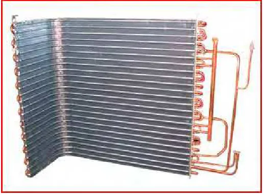
2.1.4 Evaporator
The evaporator is the component of a refrigerant system in which heat is
removed from air, water or any other body required to be cooled by the evaporating
refrigerant. Evaporators are mainly classified as flooded or direct-expansion such
dry. In flooded evaporator, the liquid refrigerant covers the entire heat-transfer
surface. In dry evaporator, a part of the heat transfer surface is used for superheating
the vapour. (Gupta J.K 2009).
Figure 5: Evaporator
8
2.2 Mechanical Air Conditioning and Ventilation
The purpose of air conditioning in a building is to control the temperature or
heat inside a room or space. Ventilation is the intentional movement of air from the
outside building to the inside. The determination of the air conditioning air flow are
depending on a various factor, such as the area of the room, the sensible heat, latent
heat, the location of the room and the function of room. For example, the server
room and control room need a twenty four hour of air condition to maintain it
temperature, so that the equipment inside the room were be able to function at it best
condition. (J. Hoff,1994).There various types of air conditioning systems available in
the market such as;
I. Room Air Conditioners (RAC)
These are also referred to as window units. Essentially, there are compact
packaged units housing all components together, namely air cooled
condenser, direct expansion evaporator and compressor.
II. Split Units
These are air cooled system comprising an outdoor condensing unit piped to
an indoor evaporator unit. The indoor unit may be aesthetically wall mounted,
ceiling mounted, concealed ducted or cassette type configuration.
III. Air Cooled Packaged Units
These are essentially larger capacity versions of RACs and Split Units. They
are normally ducted installation. Applications include all types of commercial
9 IV. Water Cooled Packaged Units
These are similar to air cooled packaged units except that the heat rejection is
not directly to the ambient air but through another medium, normally
consisting of a cooling tower and its condenser water circuit.
V. Variable Refrigerant Volume (VRV) Systems
These are essentially multi spilt systems where one outdoor condensing unit
can serve up to 8 indoor evaporator units. By means of the VRV feature there
are numerous other advantages such as length of refrigerant piping.
2.2.1 Split Unit Air Conditioning
A split air conditioning unit is one that has the two main components separate
from each other, with one being inside the building, and the other being outside. A
central air conditioning unit is nearly always a split air conditioning unit. There are
also air conditioning units called mini split air conditioners. These units operate in a
very similar way, but do not use ducts to send the air. These may provide single
room air conditioning, or cooling for multiple rooms, and are often called ductless air
conditioning units. The two main components of a split air conditioning system have
different functions. The unit situated outdoors, called a compressor, cools the air and
handles condensation.
This saves the trouble of having to find a way to drain the water created from the air
conditioning process indoors. The inside unit, called the blower, is responsible for
distributing the air to the rest of the house. This is done through a forced-air system,
usually using a fan and a series of ducts that distribute cool air to each room in the
home with a vent. An intake vent will return air to the unit.
For those who live in homes without ducts, or who feel they do not need to cool
every room, a mini split air conditioning system may be an option. This is much
simpler than trying to install the duct work for a traditional split air conditioning unit.
There is no need to worry about running ducts, or substantially cutting into walls.
10 cost more to buy initially. A miniature system works by installing an air handling
piece in the room of choice. Two lines are then connected to an outside unit.
While this will require drilling through an outside wall, it will not require the cutting
needed for air conditioning units with ducts. One line will deliver coolant to the
inside component. The other line will take away condensation. For those who need
multiple rooms cooled, several inside components can be installed to one outdoor
component.
2.2.2 Split Unit Flow rate
The split unit flow rate is needed to be determining to select the suitable split
to reach a maximum cooling capacity in the room. The volume of the selected room
are been multiple by the air change per hour (ACH) such as shown in Table 1, to get
the maximum flow rate.
11
2.2.3 Air Change per Hour (ACH)
Air change per hour is a value representing the number of times each hour
that an enclosure's total volume of air is exchanged with fresh or filtered air. An air
change doesn't represent a complete change of all air in the enclosure or structure.
The actual percentage of an enclosure's air which is exchanged in an air change
period depends on the airflow efficiency of the enclosure and the methods used to
ventilate it. (Bearg, David W,1993)
ACH equation in Imperial units
(1)
Where:
N = number of air changes per hour
Q = Volumetric flow rate of air in cubic feet per minute (cfm)
Vol = Space volume L × W × H, in cubic feet
2.3 Solar Air Condition
Solar air condition is a system that has use a solar water heater to produce a
hot water for the chillers. To produce a hot water, the solar evacuated tube was used
to get the hot water. The hot water is supplied to the generator to boil off the Lithium
Bromide solution. Water vapour or refrigerant from the generator will go to the
condenser chamber where it is condenser into liquid refrigerant. The liquid
refrigerant will flow helping by gravity into the evaporator chamber. The liquid
refrigerant is then pumped through the orifice to be sprinkle to the evaporator coil by
the refrigerant pump. The solar air condition has a component such as cooling tower
12
2.3.1 Solar Cooling Technology
Solar cooling technologies use solar thermal energy provided through solar
collectors to power thermally driven cooling machines. Cooling demand is rapidly
increasing in many parts of the world, especially in moderate climates, such as in
most EU member states. This results in a dramatic increase in electricity demand on
hot summer days, which causes an unwanted increase in the use of fossil and nuclear
energy and furthermore threatens the stability of electricity grids. As many cooling
applications, such as air conditioning, have a high coincidence with the availability
of solar irradiation, the combination of solar thermal and cooling obviously has a
high potential to replace conventional cooling machines based on electricity. Larger
solar cooling systems have been successfully demonstrated and smaller machines,
which could be used in (small) residential and office buildings, are entering the
market.
2.3.2 Components of a solar cooling system
A solar cooling installation consists of a typical solar thermal system made up
of solar collectors, storage tank, control unit, pipes and pumps and a thermally driven
cooling machine. To date, most collectors used in solar cooling systems are the high
efficiency collectors available in the market today (often double-glazed flat plate
collectors or evacuated tube collectors). New developments for the medium
temperature range (100-250°C) could increase the overall efficiency of the cooling
systems.
2.4 Solar Water Heater
These systems use the sun to heat either water or a heat transfer fluid, such as
water in collectors generally mounted on the roof. The heated water is then stored in
a tank similar to a convectional gas or electric water tank. Some systems use an
electric pump to circulate the fluid through the collectors. Some water heaters can
operate in any climates. Performance varies depending on how much energy is