Wide Band Open Ended Air Gap RLSA Antenna at 5.8GHz Frequency Band
I.M. Ibrahim1, T.A.Rahman 2, M.I.Sabran2 1
Faculty of Electronics and Computer Engineering, Universiti Teknikal Malaysia Melaka 2
Wireless Communication Centre, Universiti Teknologi Malaysia
Email:[email protected], [email protected], [email protected]
Introduction
RLSA antenna is a popular candidate for the application of Point to Point Microwave Link.[1] This is due to its capability of carrying high speed signal. RLSA prototypes has been designed and developed at the frequency range of 5725 – 5875 MHz by few researchers.[1-2] The classic design was using enclose air gap as a separator between radiation surface and ground plane.[3-4] Then, the slow wave material has been used in the RLSA cavity. The implementation of FR4 board to RLSA design recently has allowed a reconfigurable and beam shaping of radiation pattern.[5]. The open air gap cavity structure normally implemented in broadband planar antenna.[6] This structure normally provide a wide bandwidth and good return loss on the desired frequency. Therefore, an investigation of this technique and hybrid with FR4 board as a cavity material will be very interesting due to condition of easy to manufacture, lighter the antenna weight and durable.[7]
The Cavity Structure
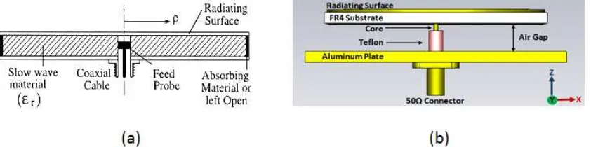
The Linear Polarized Beam Squinted RLSA (LP-BSRLSA) at 5.8 GHz antenna for Point to Point Application was designed based on LP BSRLSA GHz antenna for Direct Broadcast Satellite Receiver [1-3]. Conventionally, the RLSA antenna structure consists of a dielectric material sandwiched by copper plate. The front plate bears the radiating element while rear plate acts as a ground plane with feed element at the centre. The dielectric constant εr> 1 was chosen to suppress the grating lobes. The radiating elements are arrayed so that their radiation are added in phase along the beam direction. The structure of the investigated single-layer RLSA antenna is shown in Figure 1(a). The orientation of slots is in such a direction so as to transmit and receive waves of proper polarization, linear, and proper coupling inside the cavity.
Figure 1: (a)Conventional structure within the cavity of RLSA antenna, (b)Open ended air-gap structure of RLSA antenna
[image:1.612.101.522.581.686.2]In this research, the FR4 board with air gap distance to the ground plane has been introduced. The thickness of overall cavity is 9.6mm where the thickness of open air gap is 8mm. A 50Ω single coaxial probe coated with Teflon is used to feed the signal into the cavity as shown in Figure 1(b). The aluminium plate is used as a platform to hold the antenna and also become a ground plane. The FR4 with 1.6mm thickness with 5.4 permittivity value is used as a first layer substrate to the radiating surface. Since the design was a hybrid between air gap and FR4, the equivalent dielectric value has to be determined. In order to get the equivalent dielectric value, the equation 1 has been used.[8]
εreq ε
rn 1
1
.∑ 1 (eq.1)
The Radiating Slot Design
The theoretical slot design procedure is similar to what was proposed in [1-4]. Slot pattern has been arranged on the aperture to provide a linear polarization. A unit radiator is defined as an adjacent slot pair #1, #2, lying along the constant direction (Φ). The 200mm diameter of RLSA was chosen. The dielectric value has influenced the number of slots and the slots length on the surface of the antenna. The 16 slots pair has been constructed in the area of 200mm diameter as shown in Figure2.
Figure 2: The slots arrangement on the surface of Air Gap RLSA
Results and Analysis
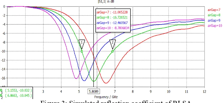
Figure 3: Simulated reflection coefficient of RLSA
Figure 4 illustrate the radiated radiation pattern of the Air Gap RLSA at E-plane. The antenna directivity gain recorded at 12.35dBi with 3.9 dB side lobe level. The main lobe squinted at 9 degree from 0 degree. The beamwidth of the main lobe is 13.3 degree. From the 3D pattern, it is clearly show the concentration of the radiated energy is on the main beam. However, a concentration of radiated energy also recorded at 60 degree and 180 degree. In overall, the radiation pattern shown directive characteristic and have a potential to be implement at point to point application.
[image:3.612.129.494.379.561.2](a) (b)
Figure 4: Simulated Radiation pattern for Air Gap RLSA (a) in 2D, (b) in3D
Conclusion
Acknowledgement
The author would like to acknowledge and express sincere appreciation to Universiti Teknologi Malaysia and Ministry of Higher Education Malaysia (MOHE) for funding this project. Appreciation also goes to University Teknikal Malaysia Melaka and MOHE for funding the author’s scholarship.
References
[1] Imran Mohd Ibrahim, Tharek Abdul Rahman, Pak Siau Wei, Johari Ahmad, AbGhaniCheWahab (2011), ”A Study on Effectiveness of FR4 as a Dielectric Material for Radial Line Slot Array Antenna for Wireless Backhaul Application”, IEEE The 17th Asia-Pacific Conference on Communications (APCC2011), Sutera Harbour Resort, Kota Kinabalu, Sabah, Malaysia, 2-5 October 2011
[2] I.M. Ibrahim, Riduan A, Tharek A.R. and Hasnain A., “Beam Squinted Radial Line Slot Array Antenna (RLSA) Design for Point to- Point WLAN Application,” in Asia Pacific Applied Electromagnetics Conference (APACE 2007), 4-6 December 2007, Melaka Malaysia.
[3] Ando, M.; Sakurai, K.; Goto, N., “Characteristics of a radial line slot antenna for 12 GHz band satellite TV reception,” in IEEE Transactions on Antennas and Propagation, vol. 34, issue 10, Oct 1986, pp. 1269 – 1272.
[4] T. Yamamoto, M. Takahashi, M. Ando, and N. Goto, "Measured performances of a wide band radial line slot antenna," in Antennas and Propagation Society International Symposium, 1994. AP-S. Digest, 1994, pp. 2204-2207 vol.3.
[5] M. F. B. Jamlos, A. R. B. Tharek, M. R. B. Kamarudin, P. Saad, O. Abdul Aziz, and M. A. Shamsudin, "Adaptive beam steering of RLSA antenna with RFID technology," Progress In Electromagnetics Research, Vol. 108, 65-80, 2010.
[6] Chen, Zhi Ning (2006),“Broadband Planar Antenna: Design and Applications”, John Wiley and Sons, West Sussex, England.
[7] Md Rafiul Islam, Tharek Abd Rahman, “Novel and Simple Design of Multilayer Radial Line Slot Array (RLSA) Antenna Using FR4 Substrate” in 19th International Zurich Symposium on Electromagnetic Compatibility, 19–22 May 2008, Singapore