FPGA Based Five-Phase Sinusoidal PWM Generator
Tole Sutikno
Dept. of Electrical Engineering Universitas Ahmad Dahlan (UAD)Yogyakarta, Indonesia [email protected]
Nik Rumzi Nik Idris, I.M. Alsofyani
Dept. of Energy Conversion Universiti Teknologi Malaysia (UTM)Johor, Malaysia [email protected]
Auzani Jidin, L. Logan Raj
Dept. of Power Electronics & Drives Universiti Teknikal Malaysia Melaka (UTeM)Melaka, Malaysia [email protected]
Abstract—Multiphase machine has became popular in many rotational drive applications due to its reliability, high efficiency and high quality of waveforms. Moreover, this machine (e.g. 5-phase induction machine) can provide more options for selecting the most optimum voltage vector since the number of switching devices of the inverter increases that can enhance torque capability and improve dynamic performances. However, the great advantageous offered cannot be realized if the switching and control strategy performed at very low sampling frequency which does not guarantee for the multiphase drive to operate at optimum operations. This paper presents the realization of five-phase sinusoidal PWM signal generator at fast sampling frequency using one-chip programmable gate array (FPGA). It can be shown that the generation of sinusoidal PWM using FPGA can perform the switching frequency of the inverter at 40 kHz switching frequency that may raise potential for excellent drive performances.
Keywords-Five-Phase Sinusoidal PWM Generator, FPGA, inverter, motor drives, power converter, VHDL
I. INTRODUCTION
In recent years, attention in multiphase inverter technology has increased due to the benefits of using more than three phases in drive applications. Multiphase motor possess several advantages, such as reduced the amplitude and increased the frequency of torque pulsations, reduced rotor harmonics currents, reduced dc-link current ripple, reduced stator current per phase without increasing the voltage per phase, increased fault tolerance, greater efficiency, lower per phase power handling requirements, improved noise characteristics, and higher reliability as compared to a three-phase motor [1-6]. In general, the 5-phase machines produce the output current 6-8% higher than those of the 3-phase and 6-phase machines [7]. The most commonly used of multiphase system which is the smallest phase number, is five-phase.
Several work on design and control of five-phase ac motor drives were published, and also a lot of modulation techniques for five-phase pulse width modulation (PWM) inverters have developed [8-12]. However, different from three-phase PWM inverters, till recently, not much works had been made in FPGA-based multiphase PWM signal generating that results in minimal input and output ripple on five-phase PWM inverters. In [13], a early model of sinusoidal PWM waveform generation for a five-phase converter using FPGA technology is presented. No work has considered as to what is the optimum technique
that result has been investigated and in minimum current ripples. In this paper, five-phase carrier-based sinusoidal PWM signal generator utilizing FPGA is presented. Relationship of the voltage vectors and switching states between three-phase and five-phase system will be reviewed in section II, and the relevant expressions are derived. Section III describes principle of five-phase PWM generating, that its implementation is showed in section IV. Results and discussions are presented in section V, and in section VI conclusion is drawn.
II. GENERALEXPRESSIONS
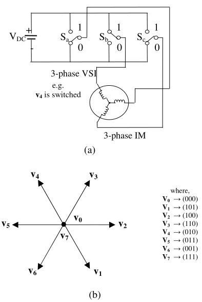
Figure 1 shows the number of switching states (or voltage vectors) provided by the 3-phase induction machine-drive system.
Figure 1. Voltage vectors and switching states in 3-phase induction machine-drive system; (a) power circuit configuration and (b) space
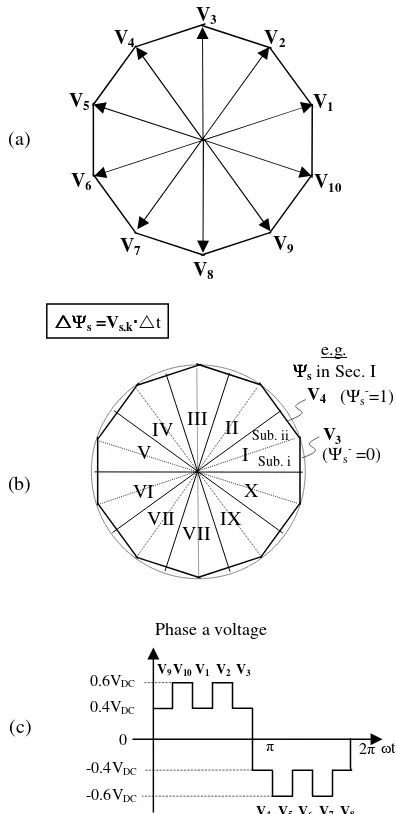
The 3-phase motor drives are supplied with a 3-phase voltage source inverter (VSI) which can only have 23= 8 voltage vectors. Figure 2 shows the number of switching states (or voltage vectors) provided by 5-phase induction machine-drive system. In comparison with 3-phase induction motor drives, the 5-phase motor drives are supplied with a 5-phase voltage source inverter (VSI) which can have 25=32 voltage vectors (i.e. 2n where n is the number of phase). In particular, the 32 space voltage vectors are composed of three sets of vectors having different amplitudes and divide the voltage vector plane into ten sectors. The relationship among the DC side current, switching states and the AC side current of the inverter with refer to Figure 2.a can be written as
(1) the flux lies in subsector ii.
In general, if the sector k is equally subdivided into Subsectors, i and ii, voltage vector of two possible voltages that uses to increase the flux (Ψs- is equal to 0) will be selected throughout Subsector i and voltage vector that uses to decrease the flux (Ψs- is equal to 1) will be used throughout Subsector ii. As the Figure 3. Decagonal flux locus with application of 10-step Voltage; (a)
voltage vector plane, (b) stator flux plane, (c) phase voltage I
Figure 2. Voltage vectors and switching states in 5-phase induction machine-drive system, (a) power circuit configuration and (b) space
stator voltage to reach at 10-step voltage limit. This particularly can be achieved when the motor speed exceeds its base speed where the application of zero voltage vectors is zero. It should be noted that the torque demand will be naturally fulfilled by the controller, which will gradually drops the applications of zero voltage vectors as the speed increases approaching its base speed. As the speed is further increased and no more zero voltage vectors are available, the selection of voltage vector will naturally transform to 10-step mode. In other words by transforming the stator flux locus to the decagonal shape, we provide the room for the stator voltage to increase beyond the decagonal boundary and the torque demand will naturally transform the stator voltage from PWM to 10-step mode.
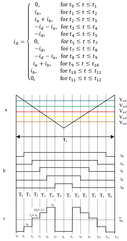
The on-off signals for the switching devices can be obtained by comparing five-phase reference signals or modulated signals to a high-frequency triangular signal as carrier signal. Figure 4 shows the phase reference signals used in this paper, which can be written as
!"
# (2)
! $"#
%& '# ( ) *"# +,-.
where +,-. is an arbitrary signal that is injected into the
sinusoidal reference signals. Because the injection signal into the phase reference signals is same, the average value of the phase-to-phase voltages will not be altered by this arbitrary signal. The arbitrary signal assumption is valid as long as the frequency of carrier (triangular) signal is much higher than the reference signals. In this condition, the reference signals can be assumed as constants during one carrier period, and the detailed inverter waveforms can be drawn as shown in Figure 5. The figure is valid during the interval A of Figure 4.
By using eq.(1), the dc input current during one carrier period, as shown Figure 5, can be written as
/ 0 0 0 0 1 0 0 0 0
2 344 567 8567 8 : 8 : 89: 8 : 8 4 567 8 : 8 : 8 4 567 8 : 8 : 8!
4 567 8!: 8 : 8#
34 567 8#: 8 : 8;
4 567 8;: 8 : 8*
4 567 8*: 8 : 8<
4 567 8<: 8 : 8 9
4 567 89: 8 : 8
34 567 8 : 8 : 8
= (3)
III. FIVE-PHASESPWMALGORITHM
IMPLEMENTATION
Figure 6 shows the design of overall experimental set-up. However, the paper only focus on FPGA based five-phase sinusoidal PWM signals generating, and the overall system is under preparation.
Due to limitation the allocated space, in depth design procedure of PWM signal generator that is easy for modifying cannot be presented. However, the overall system is hoped provide clear enough about this research in future and have capability to involve many researches in next development phase.
Figure 5. Inverter waveforms over one carrier period c
b a
Vref2
Vref1
Vref3
Vref5
Ts
Vref4
sb
sa
sc
se
sd
T0 T1 T2 T3 T4 T5 T5 T4 T3 T2 T1 T0
ib
ia+ ib
-(id+ ie)
-id
id
t0 t1 t2 t3 t4 t5 t6 t7 t8 t9 t10 t11 t12
Figure 8. PWM signal generator in higher switching frequency, b
a
Figure 7. PWM signal generator in lower switching frequency, (a) b
a
!
"
# !
$ $ %$ $
& ! % '()!
* % ++ % ( &
"! ! , %!
! !
!
!
-. /! 0 % -/()!
% '' /
-.
. /. -.
) /! " / )%
1 2 ! 3
4 (5 6
-4 (5 -.
" ! (5 7 2 8 %! 0
' (5 6 % ! / 0 '
IV. RESULTS AND DISCUSIONS
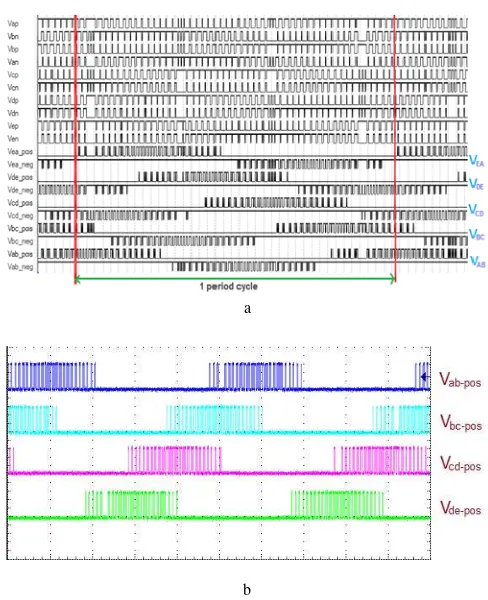
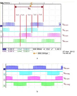
The five-phase sinusoidal PWM modules are described with mix VHDL and schematic entry design using Quartus II software. After placement and routing, the design is implemented in Altera APEX20KE, where 496 logic elements are used. The designed IC can operate at 33MHz system clock, and the switching frequency is adjustable. Figure 7 shows simulation and implementation result of PWM signal generator in switching frequency lower than Figure 8. From Figure 7 (a) is clear that the PWM signals shift 2 /5 rad. The phase shifting in hardware implementation is shown in Figure 9 (a). In Figure 9(b), leg pair of PWM signals on switching frequency higher than Figure 7(b) and 8 (b) is presented. Therefore, the PWM signals are ready to implement for controlling five-phase inverter s.
V. CONCLUSION
This paper presents the realization of a programmable five-phase sinusoidal PWM signal generator based on FPGA. Relationship of the voltage vectors and switching states between three-phase and five-phase system have been reviewed, and the relevant expressions have been derived, and then principle of five-phase PWM generating have been
described. The proposed scheme was implemented and tested using an FPGA technology. Experiment results show that the constructed design can acquire excellent operating performance. It is believed that such five-phase PWM control IC’s will become key components in power converter and motor drives of the future.
ACKNOWLEDGMENT
The authors would like to thank the Universiti Teknologi Malaysia (UTM) and Ministry of Higher Education (MOHE) of the Malaysian government for providing the funding for this research.
REFERENCES
[1] E. E. Ward and H. Härer, "Preliminary investigation of an invertor-fed 5-phase induction motor," Electrical Engineers, Proceedings of the Institution of, vol. 116, pp. 980-984, 1969.
[2] E. A. Klingshirn, "High Phase Order Induction Motors - Part I-Description and Theoretical Considerations," Power Apparatus and Systems, IEEE Transactions on, vol. PAS-102, pp. 47-53, 1983. [3] K. N. Pavithran, et al., "Studies on inverter-fed five-phase induction
motor drive," Power Electronics, IEEE Transactions on, vol. 3, pp. 224-235, 1988.
[4] S. Williamson and S. Smith, "Pulsating torque and losses in multiphase induction machines," Industry Applications, IEEE Transactions on, vol. 39, pp. 986-993, 2003.
[5] E. Levi, "Multiphase Electric Machines for Variable-Speed Applications," Industrial Electronics, IEEE Transactions on, vol. 55, pp. 1893-1909, 2008.
[6] O. Lopez, et al., "Multilevel Multiphase Space Vector PWM Algorithm," Industrial Electronics, IEEE Transactions on, vol. 55, pp. 1933-1942, 2008.
[7] B. Zhang, et al., "Comparison of 3-, 5-, and 6-phase machines for automotive charging applications," in Electric Machines and Drives Conference, 2003. IEMDC'03. IEEE International, 2003, pp. 1357-1362 vol.3.
[8] J. W. Kelly, et al., "Multiphase space vector pulse width modulation,"
Energy Conversion, IEEE Transactions on, vol. 18, pp. 259-264, 2003. [9] R. Hyung-Min, et al., "Analysis of multiphase space vector pulse-width
modulation based on multiple d-q spaces concept," Power Electronics, IEEE Transactions on, vol. 20, pp. 1364-1371, 2005.
[10] A. Iqbal, et al., "Generalised Sinusoidal PWM with Harmonic Injection for Multi-Phase VSIs," in Power Electronics Specialists Conference, 2006. PESC '06. 37th IEEE, 2006, pp. 1-7.
[11] P. A. Dahono, et al., "Output Current-Ripple Analysis of Five-Phase PWM Inverters," Industry Applications, IEEE Transactions on, vol. 45, pp. 2022-2029, 2009.
[12] D. Casadei, et al., "A new carrier-based PWM strategy with minimum output current ripple for five-phase inverters," in Power Electronics and Applications (EPE 2011), Proceedings of the 2011-14th European Conference on, 2011, pp. 1-10.
[13] P. Adhikari and M. Okaro, "Five-level five-phase PWM signal generation using FPGA," in North American Power Symposium (NAPS), 2011, 2011, pp. 1-5.
Figure 9. PWM signal generator based on FPGA, (a) Phase shifting of PWM signals, (b). Leg pair of PWM signals on