CHARACTERIZATION OF A STRUCTURE- BORNE SOURCE
USING THE RECEPTION PLATE METHOD
Noor Farizaa*, Azma Putrab, Hairul Bakric and Roszaidi Ramland
Faculty of Mechanical Engineering, Universiti Teknikal Malaysia Melaka, Hang Tuah Jaya 76100 Durian Tunggal, Malaysia.
a
[email protected], [email protected], [email protected]
d
Abstract-This paper presents the characterization of vibration strength obtained from reception plate method by applying the mobility concepts. It describes a laboratory-based measurement procedure, which determines the strength of a vibration source in terms of the total squared free velocity of the source. The source used in the experiment is the small electric fan motor installed on high mobility aluminum panel in order to neglect the influence of the source mobility. The complexity of the mobility at the contact points are reduced using the single value of effective mobility. The aim is to validate the data obtained from the reception plate method with one from the direct measurement. Thus, this research is expected to give a simple but accurate way to determine input power from a structure-borne sound source.
Keywords- : reception plate method; effective mobility;
squared free velocity; structure-borne source; input power
I. INTRODUCTION
Annoyance due to noise in a building is still one of major problems in engineering. This noise is often caused by vibration from rotating machines which are channeled to the building structure. This then carries the vibrational waves and radiates noise into the air. The most risky structure is the one of industrial or factory building which contains many vibrating machineries, such as the iron and steel industries, foundries, saw mills, textile mills and crushing mills among many others. Those machines are capable of injecting high level of vibration which not only causes noise but also hazardous to the structure where the machines are installed.
The treatment of structure-borne sound sources remains a challenging problem. Structural excitation to a building floor, for example, by active components like pumps, compressors, fans and motors is an important mechanism of vibration and noise generation and also an important parameter to obtain the potential vibration input power [1]. The vibration from the machines transmits vibration power to the supporting structure in a complicated combination of motions. Therefore to obtain an accurate prediction of the injected input power from such sources, both the source and the receiver must firstly be characterized.
This research will start with model idealization where the source is assumed to have structural mobility much greater, smaller or comparable than that of the receiver. Important parameters which determine the strength of the
structure-borne sound source will be studied. Receiver structure with infinite extent will also be assumed for analysis. In practical application, however, the lack of knowledge in the excitation force creates variability in the input power. Therefore some uncertainties such as the amplitude, phase and location of the excitation force will be investigated. Quantifications of the maximum-minimum band, mean and variance of the vibration input power will be presented and experimental validation will be carried out. The research is expected to give a simple but accurate way to determine input power from a structure-borne sound source.
For example while planning to install a huge vibrating machine, the supplied information of the machine’s vibration input power allows a structural engineer to take preventive action, such as to ensure the support structure is strong enough to absorb the potential vibration power. This will give time to reinforce the structure or install some damper at the certain locations e.g. at the contact points between structure and source [2].
II. MATHEMATICALFORMULATION
A. Vibration input power
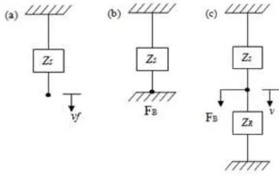
Figure 1(a) shows a diagram of a source having impedance ZS and free velocity vf. If the source is then attached rigidly on a rigid surface (Figure 1(b)), the resulted force FB is called the blocked force. From definition
S f f S B
Y v v Z
F (1)
where ZS and YS are the impedance and mobility of the source, respectively.
If the source is now connected to a receiver with impedance ZR (Figure 1(c)) and assuming both the source and receiver move in the same velocity v, the blocked force is the sum of the force from the source FS and force at the receiver FR. The blocked force can thus be written as
Z Z
v FF
FB S R S R (2)
Figure 1: Mathematical diagram of a vibration source and a receiver.
By re-arranging Eq. (2), the velocity of the source-receiver system can be obtained in terms of the properties of the source and receiver
S R S R B R S R B R S B Z Z Z Z F Z Z Z F Z Z F v 1 1 1 1 1 1
(3)
Equation (3) can also be written as the function of the mobility
Y
1
/
Z
and the free velocity asv YR YS YR vf
1 ) (
(4)
Assume the source is attached to the receiver through a single contact point; the power injected to the receiver,
Pin is defined by
2 Re 2 1v Z
Pin R (5)
By substituting Eq. (4) into Eq. (5), the input power can be expressed as
2 2 2 2 1 Re 2 1 Re 2 1 f R S R R f R S R R in v Y Y Y Y v Y Y Y Z P (6)Equation (6) can then be simplified and be written as
2 2Re 2 1 f R S R in v Y Y Y P
(7)
For N contact points, Eq. (7) is expressed in terms of matrices and vectors
* *
1
* 1 Re 2 1 f R S R T R S T f in v Y Y Y Y Y v P (8)where
vf the free velocity is vector and
YS,R is themobility matrices. For six component of excitations (3 translational and 3 rotational), the required matrix size is6N6N. However, in this paper, only translational force perpendicular to the receiver plane is taken into account. The matrix size then reduces toNN given by
NN N N Y Y Y Y Y Y Y Y 1 22 12 1 12 11 (9)
where Yij is the point mobility for i = j or transfer mobility fori j.
B. Reception plate method
Using the reception plate method, a machine under test is attached on a plate under its normal operating conditions. The total structure-borne power transmitted is obtained from the measured spatial average of the mean square plate velocity
2
R in ηSmω v P
(10)
where is the damping loss factor of the plate, S is the
plate area, m is the mass per unit area,
2
R
v
is thespatially average of mean- squared velocity and ω is the operating frequency. Thus, the damping loss factor can be obtained by
2Re
t PY
M
Y
(11)For YP is the point mobility of the reception plate, M the total mass and 2
t
Y is the spatially average squared
transfer mobilities.
By using high mobility reception plate where
Y
R
Y
S,the Eq.(8) and (10) is reduced to be
Eq. (11) is difficult to solve in obtaining the free velocity
v
f of the source under test, as the velocity ateach source feet itself carries phase information.
However, this can be treated by assuming in phase velocity for all the feet and small variation between the point and transfer mobilities from Eq. (9) at the contact points. For this purpose, the concept of effective mobility is introduced.
C. Effective Mobility
The power through ith contact (i = j), when considering one component of excitation, the translational components perpendicular to the receiving surface where the point mobilities are replaced by effective point mobilities.
denotes effective in such a way thatcontributions from all points and components are taken into account.
In contrast to the matrix formulation, the concept of effective mobility provides better insight into the order of significance of different transmission paths.
In this concept, the effective mobility sums the point and transfer mobilities for each contact point to be a ‘single mobility’ [6,7]. For zero phase assumption, it is expressed as
Nj i i
ij ii
eff
i
Y
Y
Y
1
(13)
For random phase assumption, it is given by
Nj i i
ij ii
eff
i
Y
Y
Y
1 2 2
2
(14)
Thus, by using the effective mobility, Eq. (12) may be introduced as
2
,
2 1
Re 2 1
f N
i
eff i R
R v
Y v
m
S
(15)By assuming small variation of
Y
Reff,i at each contact point on the reception plate, Eq. (15) may be simplified to
N
i f eff R
R v
Y v
ω
m S
η 2 1 2
Re 2 1
(16)
From Eq. (11), the total squared free velocity
Ni f
v 2 of
the tested structure-borne source can be obtained. Thus, the total structure-borne power transmitted is obtained from the measured spatial average of the mean square plate velocity and YReffis the average effective mobility for all contact points.
III. EXPERIMENTALWORKANDRESULTS
The experiment was conducted using a table fan motor as the source and an aluminium plate of 1 mm thick and dimensions 1.40.8 m as the receiver.
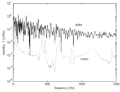
Figure 1 below, shows the comparison between the measured mobilities of the motor (source) and the receiver (plate) using the instrumented impact hammer and accelerometer. The mobility of the receiver must be larger to apply Eq. (16). By the average of the plate mobility, it can be seen that 20 dB is larger than the mobility of motor. So, the source mobility can be neglected when using the Eq. (12).
Figure 1: Comparison between the source (motor) and the receiver (plate) mobilities using in the experiment.
The variation of the effective mobilities for zero and random phase assumption in one- third octave bands are shown in Figure 2(a) and Figure 2(b).
The results show that in general, the variation is within 5 dB for each contact point location at the reception plate.
In order to obtain the spatially average of mean-squared velocity 2
R
v from Eq. (16), the motor was attached on high mobility reception plate through two contact points and operated at normal condition.
(a)
(b)
Figure 2: Effective mobility of the reception: (a) zero phase and (b) random phase.
Figure 3: Measured spatially average of mean-squared velocity of the reception plate.
Then, eight locations of point were chosen as the measurement points scattered on the plate to represent the spatial average. The result of the measured spatially average of mean-squared of the reception plate is shown in Figure 3.
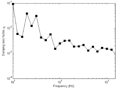
The damping loss factor of the reception plate is plotted up to 2.5 kHz in one-third octave bands by using the Eq. (11) that is shown in Figure 4. It can be seen that, the
response dies off above 1.5 kHz. This shows that, the effective frequency range of excitation is given by the motor.
Figure 4: Measured damping loss factor from the reception plate.
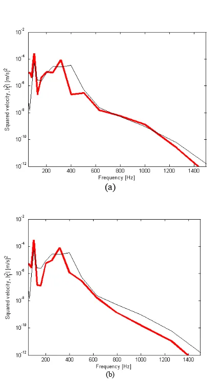
Finally, the free velocity from the reception plate method can be obtained by using the Eq. (16). Figure 5,
shows the estimated squared free velocity,
Ni f v 2
compared with that from the direct measurement. The latter was conducted by hanging the motor and the velocity was measured at each feet using accelerometer.
A good agreement between the estimated squared velocity and that from the measurement can be seen in Figure 5(a) for zero phase assumption. A discrepancy between 300-700 Hz might be because of the interference due to the small spatial range between the contact points. The same condition also can be seen from Figure 5(b) for random phase assumption. However, both results differ roughly above about 800 Hz. This indicates that the phase of excitation of the motor still in phase up to 2.5 kHz.
IV. CONCLUSION
Determination of the vibration strength of a structure-borne source represented by the free velocity has been conducted using a reception plate method with high mobility panel. This is proposed for a mechanical installation to a plate-like structure. A good agreement is achieved for the squared free velocity of the source between the result from the method and that from direct measurement.
(a)
(b)
Figure 5: Comparison of squared free velocity between that obtained using reception plate method (thick line) and that from direct measurement (thin line): (a) zero phase effective mobility (b) random
phase effective mobility.
ACKNOWLEDGEMENT
The authors would like to acknowledge the Ministry of Higher Education (MoHE) Malaysia for supporting this work under Fundamental Research Grant Scheme; FRGS/2010/FKM/TK03/15-F00109.
REFERENCES
[1] Soong. State of the art review: active structural control in civil engineering, Engineering Structures, 1988.
[2] Bies, D.A. and Hansen, C.H. Engineering Noise Control: Theory and Practice. London: E&FN Spon, 1996.
[3] M. Spah, B. M. Gibbs, and H.-M. Fischer, New laboratory for the measurement of structure-borne sound power of sanitary installaions, Forum Acusticum, Budapest, 1907 – 1912, 2005. [4] Pieter Schevenels. Identification Of Structure-borne sound
paths of service equipment in buildings using
structural-acoustic reciprocity. Proceeding of the 16th International
Congress ofSound and Vibration, Kraków, Poland, 2009.
[5] B. M. Gibbs, R. Cookson and N. Qi. Vibration activity and mobility of structure-borne sound sources by a reception plate method, Journal of the Acoustical Society of America, 123:4199- 4209, 2008.
[6] B. A. T. Petersson and J. Plunt, On effective mobilities in the prediction of structure-borne sound transmission between a source and a receiving structure, Part 2: Estimation of mobilities, Journal of Sound and Vibration, 82(4), 531-540, 1982.
[7] B. M. Gibbs, R. Cookson and N. Qi. Vibration activity and mobility of structure-borne sound sources by a reception plate method, Journal of the Acoustical Society of America, 123:4199-4209, 2008.
[8] B. A. T. Petersson and B. M. Gibbs, Towards a structure- borne sound source characterization, Applied Acoustics 61, 325-343, 2000.