Harvesting Energy From Flood Mitigation Ponds Using Water Wheel
1Assocciate Professor Ir. Dr. Abdul Talib Din,
2Mohd. Yazid Othman,
3Mohd.
Yuhazri Yaakob
1,2 Faculty of Mechanical Engineering, 3 Faculty of Manufacturing Engineering
Universiti Teknikal Malaysia Melaka,
Industry Campus, Hang Tuah Jaya, 75450 Melaka, Malaysia Tel: +606-2346887, Fax: +606-2346884
Email : [email protected]
Abstract
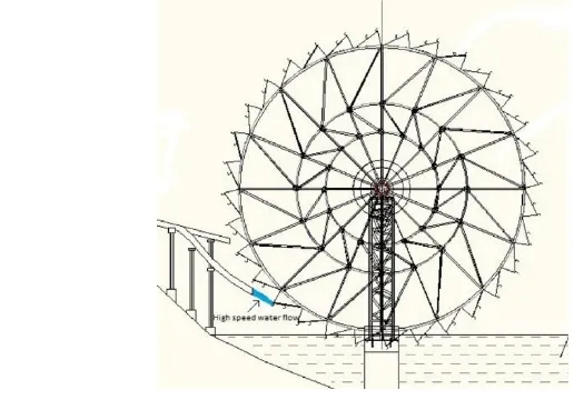
Flood mitigation pond is a compulsory landscape structure that the developer needs to provide to comply with the Malaysia Building by Laws. Normally flood mitigation ponds in a housing estate or any land development are located at different elevation and connected to each other by a cascade flume. The flow of water in this cascade flume is capable of generating sufficient power for landscape lighting or aerators to treat the pond water. Aeration in the pond water is very important in order to create conducive living environment for the flora and fauna in the pond. The research was carried out by installing a water wheel at the cascade flume to tap the potential energy from the head different of the water flowing in-between the two ponds. The water wheel uses both kinetic energy of the water jet created in a specially designed pipe end and also by means of the weight of water accumulated in the fiberglass buckets fixed at the perimeter of the wheel. Two 200mm diameter PVC pipe installed leading to the wheel bucket for this purpose. If there is heavy rain, the storm water will quickly fill up the pond thus create a huge flow rate of water in the 200mm diameter in one of the tapping pipe and produce a powerful jet at the pipe nozzle to push the scoop beside the bucket. At the same time the water in the other 200mm diameter PVC pipe fill up the buckets to move the bucket downward by gravity. The water wheel size is 10 meter diameter and supported by two pillars made of welded carbon steel pipe trusses. The rotation of wheel is enhanced by the inertia force due to the self weight of the wheel and the weight of water accumulated in the bucket, transmitted to a 1:600 speed multiplication system using gear and V belt. Once the bucket which is filled with water reached the bottom of the wheel, it will immediately discharge the water into the lower pond thus lessen the weight of the bucket for upwards movement to the top of the wheel. This process will go on until the wheel turn at a sufficient torque and rpm to generate electrical energy which then transferred to the battery bank located at the footing of the wheel structure. The electrical energy from the battery is used to light up the garden lighting and aerator machine in the ponds by means of inverter which converts the dc current to ac current. The wheel could be further improved in term of torque and rpm by reducing friction at the rotating shaft bearings and also by aerodynamic shape of the buckets and other rotating structures to reduce air resistance.
Keywords: water wheel, green energy, renewable energy, flood mitigation pond, energy conversion, potential energy.
1.
Introduction
The water wheel is an ancient machine which uses falling water in order to create power by using a set of paddles. These paddles which are mounted around a wheel can generate the force as the water moves the paddles. As a result, the rotation of the water wheel can be transmitted to machinery via the shaft of the wheel [2]. The water wheel was probably the first method of creating mechanical energy that replaced humans and animals where it was widely used for crop irrigation, grinding grains, supply drinking water to villagers and drives the mills. In the early century, the horizontal water wheel was used for transferring the power to the milling mechanism but this type of water wheel produced inefficient energy and was gradually replaced by vertical water wheel design.[1][4]
wheels lose of their power. The overshot water wheel was designed to receive water from above which need to construct channels. The overshot water wheel requires gears and an elevated stream of water. The breastshot water wheel was the common water wheel type which commonly used by American industry during industrialization era. [1][3][4]
The undershot water wheel is commonly used on boat or floating mills. The undershot water wheel is the least efficient of all water wheels. Breastshot and undershot water wheel have larger to make up in torque. The modern invention from water wheel is known as hydraulic turbine.
2.
Problem Statement
The power performance of water wheel is largely influenced by the rotation of the water wheels. The rotation of water wheel is used to drive the shaft which connected to the electric generator. The water flow from the UTeM’s lake is used to shoot a jet to the bucket or blades of water wheel below the center axle. This design is not efficient if compared with the overshot and breastshot design. The new improved design shall be made to address the problem of low power generation or low efficiency of the existing UTeM s water wheel.‟
Most of the generator used in the industries and the residential domestic consumers are normally supplied by the diesels or methane gas generators which release polluting flue gases into the atmospheric air. This is not recommended for greening the earth, thus a green solution for power generation must be sought.
Flood mitigation pond is a compulsory landscape structure that the developer needs to provide to comply with the Malaysia Building by Laws. Normally flood mitigation ponds in a housing estate or any land development are located at different elevation and connected to each other by a cascade flume. The flow of water in this cascade flume is capable of generating sufficient power for landscape lighting or aerators to treat the pond water. However these flood mitigation pond’s potential in generating power are wasted by just flowing freely without tapping its energy contained in the term of water flow kinetic energy.
3.
Objective
The objective of this project is to study the existing performance of UTeM’s water wheel and identify all possibilities for improvement.
4.
Scope of Study
The scopes of study of this project
are:-a. to carry out literature review on the performance of the water wheel from the ancient time till to date. b. To carry out computer simulation for water wheel movement/torque for every conceptual idea
obtained.
c. The last scope of the project is to suggest the improvement on the current design and rectify it to check the real performance of the water wheel when put into operation after made some modifications.
5.
Literature Review
Energy is the ability of the system to perform the work. It can exist in several forms such as kinetic energy, potential energy, mechanical energy, heat energy, chemical energy, electrical energy, nuclear energy and other form. The classification of energy has two categories which are renewable energy and non-renewable energy. The non-renewable energy is that the source of energy cannot be reproduced such as fossil fuels which are petroleum, coal, natural gas and uranium.
emissions by sources and removals by sinks of all greenhouse gases.[6]
The commercial demand for energy consumption is mainly driven by industrialization. Malaysia has declared the renewable energy as the country’s fifth energy supply mix in order to diverse the energy source is made up of gas (70 percent), coal (22 percent), oil (2 percent) and hydro power (6 percent). The Ninth Malaysia plan has considered the importance of renewable energy as the element in economy growth which emphasis towards energy efficiency on production and utilization. Under the Small Renewable Energy Power Programme (SREP), small power plants to generate renewable energy can apply to sell electricity to the utilities companies through distribution grid systems. This project applies all type of renewable energy including mini hydro plant. [6]
Among all renewable sources of energy, the mini hydro power which uses water is the better choice as one of the most cost effective and reliable energy technologies for producing clean electricity generation. The advantage of small hydro against wind, wave and solar power are[5]:
a) A high efficiency (70 - 90%), by far the best of all energy technologies
b) A high capacity factor (typically >50%), compared with 10% for solar and 30% for wind.
c) A high level of predictability, varying with annual rainfall patterns.
d) Slow rate of change; the output power varies only gradually from day to day (not from minute to minute).
e) It is a long-lasting and robust technology; systems can readily be engineered to last for 50 years or more.
The mini hydro power plant has the potential to provide energy in remote and hilly areas where the extension of the grid system is uneconomical. The modern technology to generate energy by hydropower is by using turbine. The turbine is the revolution of technology from the concept of water wheel. The water wheel is the earlier machine which used to generate energy in old civilization history. It has its own potential to generate energy where it can diverse the energy generation by applying hydropower. The increase of the energy demand to generate the country growth has become the challenge in energy management which need to fulfill the requirement of low-carbon and cost-competitive energy technologies that can respond to the emerging major challenges of climate change, energy security, and access to energy [7] [10].
5.1
Water Wheel
The water wheel is the system of harvesting the usable power from the water flow. It is one of the earlier machines that created by human which use the flowing or falling water to create power by the set of paddles mounted around the wheel. The water wheel working principle uses the force of flowing water which points toward the paddles causing the rotation of the wheel. The rotation of the wheel is transmitted to the machinery via the shaft of the wheel.[8][12].
There are two type of orientation of the water wheels which are horizontal and vertical. Each orientation has varies designs in term of working principle. The horizontal water wheels rotating about a vertical axis while the vertical water wheels rotating about a horizontal axis.
5.1.1 Types of Water Wheel
There two orientation of the water wheels which are horizontal and vertical. Each orientation has varies design in term of working principle. The horizontal water wheels rotating about a vertical axis while the vertical water wheels rotating about a horizontal axis. The types of each orientation as follows:
a. Horizontal water wheel
Figure 2.1 Horizontal water wheel create by China civilization [8]
b). Vertical water wheel
Basically there are four types of vertical water wheel which are:
( i ). Undershot water wheel
The undershot water wheel is mounted vertically where the rotation of the wheel is cause by the water striking the paddles or blades at the bottom of the wheel. The undershot water wheel is one of the oldest types of wheel movement mechanisms. This type of water wheel is generally the least efficient compare to other vertical water wheel.[9]
The advantage of this water wheel is cheaper and simple to build because it does not require the elevation channel of water in order to move the wheel or in the other word or it has no advantage from the head. The disadvantage of this water wheel is less powerful and only suitable for the flow rate is sufficient to provide torque.[10]
The undershot water wheel is suitable with the shallow streams in the flat country. Besides that, it can install on the floating platform. This water wheel used the kinetic energy in the flowing water to push the flat paddles. The further development of this wheel is used curved blades which made more effective use of energy in the flowing water. This technology makes the wheel works without large head of water where it can used in any flowing water at a certain speed in sufficient quantity.[9][10]
(ii). Overshot water wheel
The overshot water wheel is mounted vertically where the rotation of the wheel is cause by fall water that strike paddles, blades, or buckets near the top of the wheel. This type of water wheel is also known as backshot wheels where the water goes down behind the water wheel. The overshot water wheel needs the water channel to the wheel at the top and slightly to one side in the direction of rotation. When the water flows through the channel at the top of the wheel, it will collect in the buckets in the half side of the wheel which make it heavier than the other empty bucket side. As the result, the weight bucket has turned the wheel and the water flows out in to the tail-water when the wheel rotates enough to invert the buckets.
The advantage of this water wheel is it can use all water flow for power. The design of this water wheel gain the double advantage of gravity where it makes the force of the flowing water partially transferred to the wheel and the weight of the water descending in the wheel buckets also create additional energy. Besides that, the wheel does not require rapid flow in order to rotate the wheel. The disadvantage of this type of water wheels is the head of water must greater than the diameter of wheel in order to channel water into the top of the wheel. As a result it cause more cost in term of installation but this cost repays by extracting more energy from the water available.[9][10] This type of water wheel is suitable at hilly or mountainous country because the mechanical power is determined by the wheel physical size and the available head. It demands exact engineering and significant head which require investment in constructing a dam, millpond and waterways. The alternative approach is by lengthy flume or penstock.[10]
Figure 2.3 Overshot wheel[9]
(iii). Breastshot water wheel
The breastshot water wheel is mounted vertically where the rotation of the wheel is cause by falling water striking the buckets near the centre of the wheel s‟ edge or just above it. It is the most common type water wheel in the United Stated of America which has powered the America industrial revolution.[9]
This breastshot wheel are less efficient compare with overshot wheel but more efficient than undershot wheel. This type of water wheel is chose in order to extract the power from the stream which provided a head of water which insufficient to power an overshot water wheel. The water channel is place at about the axle height. As the water flows, it will strike the bucket and through the breast of masonry which constructs to help retain the water in the wheel as it descended to its lowest point. [9][10]
Figure 2.4 Breastshot wheel[9]
(iv). Pitch back water wheel
The pitch back water wheel is mounted vertically where the rotation of the wheel is cause by the water that position at the near top of the water wheel. It can be consider as the variation on the overshot water wheel. The different between pitch back wheel and overshot wheel is the water is vertically downward which can cause it rotate in the opposite direction to overshot water wheel.[9]
This water wheel has similar rotation as the breastshot water wheel which also known as a „high breastshot wheel‟. This type of water wheel combines the advantages from the breastshot and the overshot operating system by the full amount of potential energy that release by the falling water is control as the water descends the back of the wheel.[9]
The advantage of the backshot water wheel is the wheel continues to function until the water in the wheel pit well above the height of the axle while any other overshot wheel will be stopped or even destroyed. This type of water wheel is suitable for the streams that experience extreme seasonal variations in flow and reduces the need for complex sluice and tail race configurations.[9][10]
The backshot water wheel may gain the power from the water flow through the bottom of the wheel where it not depend only the weight of the water falling in the wheel buckets. The cost for installation this water wheel is same as the overshot water wheel. [10]
International Conference and Exhibition on Sustainable Energy and Advanced Materials (ICE SEAM 2011) Solo-Indonesia. October 3-4, 2011.
6. Methodology
Basically, the project planning consists of a flow process that need to follow through the progress of project until the final solution has been achieved. The whole process of project starting from literature review, understanding principles of the existing water wheel, observation and data recording, data analysis, computational simulation and design for improvement.
6.1 Understanding the Existing Water Wheel Working Principle
This process is related with the searching information where all the information needs to understand and learn each element that related on the project. This process is important as it contribute to the overall process of this project especially in analysis or design process that will be done later.
6.2 Observation and Data Recording for The Existing UTeM’s Water Wheel
The observation is used to study and gather the information on the activity while the data recording is meant for data collection of the actual existing design parameters without any adjustment or amendment. It involves the visual inspection such using naked eyes, camera or recording instrument. Basically, the type of observation that used in this project is the direct observation during stationary or moving. There are two types of direct observation which are continuous monitoring and time allocation. The continuous observation is the method of observing the activity as many time as possible by naked eyes and camera. The time allocation is the method where the observer selecting the time for the observation process needs to be done. This method is more practical and time saving.[13]
The variable parameters need to be determined before starting the observation process. Basically, there are 3 variables need to consider which are controlling variable, manipulative variable and dependent variable. In this observation process, the control variable is the water wheel, head of flume, gearbox ad generator while the manipulation variable is types of water flow through the flume. The dependent variable is the revolution of water wheel (rpm), efficiency of water wheel electrical generation.
6.2.1 Discrete Observation Setting
The indicator must be classified for the types of water flow level. There are three differentiations of water level needs to be considered while doing this observation which are low, normal and high. The low water level may occur during the semester break or weekend. This is because the source of water from the upper level lake comes from the buildings which include water from the toilet, canteen, laboratory, and others. The normal water level occurs during the working hours in the university. Besides that, it also may happen during the drizzly rain. Lastly, the high level water level may occur during the heavy rain or rainy season. The reason of classified of water level is to observe the effect of water level with the movement of the water wheel.
The time sampling method is used after the water level was identified. The revolution of water wheel per minutes is observed and record for the data collection. Besides observe the revolution and collect the data, there are other matters needs taking into account such:
a) The pattern of water wheel rotation? What influence it?
b) How much the water can be filled in the bucket?
c) How the gearboxes react with the rotation of wheel?
6.3 Data Analysis
The data from the observation is used to analyze the performance of water wheel. The collections of the data have been carried out for 3 different situations according to level of water at the upstream pond. The critical data is the rpm of the wheel. This rpm value is used to calculate the efficiency of water wheel performance and its torque. The efficiency of water wheel can be determined by calculating of their output energy over the input energy. The work done by a water wheel is the kinetic energy transferred in term of radial movement when the water wheel is rotated over a circular distance by an external force which is the water potential and kinetic energy.
6.3.1 Input data analysis
Work input is the force exerted on water wheel either by water kinetic energy or by gravitational force that result to the rotation of the water wheel. Basically, there are two forces that move the UTeM’s water wheel which are the weight of the water in the buckets of water wheel and the force of water jet onto the semicircular PVC pipe located midway inside the bucket.
The weight of water that fills up the buckets would cause the radial moment of water wheel. As the water start to fill the buckets, it needs to overcome the friction force of the bearing in water wheel in order to start rotate the wheel. The weights of water which slightly over the friction force of the bearing can cause the wheel start to rotate downwards. The force created is the radial component of vertical weight F = mg
Figure 3.2 illustration of water weight torque
The total weight of water that cause the water wheel to rotate can be calculate by apply the Newton’s 2nd law where the net force on a body is equal to the product of the body’s mass and acceleration of the body.
International Conference and Exhibition on Sustainable Energy and Advanced Materials (ICE SEAM 2011) Solo-Indonesia. October 3-4, 2011.
Figure 3.3 illustration of water jet torque
The theorem of the force exerted on solid body is given by the force exerted on the fluid in control volume in given direction is equal to the rate of change of momentum in given a given direction of the fluid passing through the control volume. This theorem can express in equation by;
F = ṁoutVout - ṁinVin (1)
Where is ṁ is mass flow rate of water, V is is velocity of the water and F is force exerted on solid body by the water. The total force exerted on solid body can express as by;
F = F1 + F2 + F3 = ṁoutVout - ṁinVin (2)
Where F1 is the force exerted on the fluid by any solid body, F2 is the force exerted on the fluid by solid body force and F3 is the force exerted on the fluid by the fluid outside the control volume. This equation can be simplify by make the assumption where the reaction force is same as force but different in direction, the force can be neglected due to the gravity, and assume the pressure is constant everywhere for free jet which the force is equal to zero. The assumption can show in equation which divides into two directions;
in x direction : Rx = (Vṁ in – Vout)x (3)
in y direction : Ry = ṁ(Vin – Vout)y (4)
The resultant of both directions is the total force exerted on the curved plane. It can be show as;
R
=
√
R
2x+
R
2y (5)The direction of water flow jet is express by;
Ø = tan-1
R
xR
y(6)
The total work input is the summation of the input force at each buckets and the water flow exerted on curved plane that makes the rotation of water wheel. It can be expressed by;
Wi =
∑∫
θiθf
Where Wi is the work input to the system, θi is the initial angular displacement of rotating body, θf is the final
angular displacement of the rotating body, R is the resultant force exerted on the body, and
dθ
is the change in angular displacement.6.3.2 Output data analysis
Work output is the work produce by the system. The rotational of water wheel produce the work that use to electric generation. It is important to analyze the torque produce by water wheel in order to know the work that can be generate from that water wheel.
The data collection for angular velocity of water wheel is use to calculate the torque. The angular velocity is measure in revolution per minutes. The angular velocity may vary because the rotational of water wheel is not constant because the flow of water use to move the water wheel is not constant. When there is a change in angular velocity or velocity is not constant, the water wheel has the angular acceleration. This situation can be calculated by using the formula angular acceleration which is;
α =
t
2−¿t1ω
2−¿ω1¿
¿
rad/s2 (8)
Every rotational object has its own moment of inertia. The moment of inertia is also known as mass moment, rotational inertia, polar moment of mass, and angular mass. The moment of inertia is measure of an object resistance to change its rotation. The moment of inertia can derive from the kinetic energy equation by [9];
K =
∑
i=1 N1
2
mi v
i2
=
1
2
ω
2(
∑
i=1 N
m
ir
i2)
(9)Where the moment of inertia is;
I =
∑
i=1N
m
ir
i2 (10)I =
∫
r
2dm
(11)The rotating moment of inertia of body is not only involves its mass but also how the mass is distributed. So the different shape of body can cause the different in their moment of inertia. The water wheel consist of structure of truss which difficult to calculate the total moment of inertia. The moment of inertia for water wheel is assuming as solid body such a cylinder that rotate at fix axis.
The moment of inertia can use to calculate the torque require to rotate the water wheel. Torque is the tendency of force that cause or change the rotational motion of a body. Torque can be express as;
τ = I α (12)
International Conference and Exhibition on Sustainable Energy and Advanced Materials (ICE SEAM 2011) Solo-Indonesia. October 3-4, 2011.
Wo = τ( θf - θi) (13)
Where Wo is the work output of the system, τ is the torque of the rotating body. Therefore, the rate of work
done is the power which can be expressed by;
P =
dW
dt
=
τ
dθ
dt
= τω (14)6.3.3 Mechanical efficiency
Mechanical efficiency is the effectiveness of the mechanical system in doing the work. It is the ratio of the work output to work input that can be expressed by;
ε =
W
oW
i(15)
Where ε is mechanical efficiency of the system,
W
o is work output done by the system, andW
i is work input done to the system.6.4 Computational Simulation
The simulation software that is used to run the simulation is ANSYS Fluent. There are four steps needs to follow in simulating the water wheel operation;
a) CAD data: Generate 3D drawing b) Pre-processing: Set parameter
c) Processing: Run the simulation or solver execution d) Post- processing: Result of simulation
7.0 Results and Discussion
7.1 Analysis of Data
Analysis done by means of the mathematical model and formulation in order to determine the existing performance of UTeM’s water wheel.
7.1.1 Velocity of the water through pipe
The velocity of water through pipe can be analyzed by applying of mechanics of flowing fluid that can be expressed as;
H =
P
ρg
+v
2
2
g
+ z (16)Where H is the total head;
P
ρg
is the pressure head;v
22
g
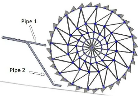
is the velocity head; and z is the potential head. The data that had been collected from the UTeM’s water wheel as per table 7.1 below;Type of pipe Total head (m) Potential head (m)
Pipe 1 10 8
Pipe 2 10 5
The density of water is 1000kg/m3 ; atmospheric pressure is 101.325 kPa; and the gravitational force is 9.81 m/s2.
Using equation (16), the velocity of water can be calculated to be 6.76 m/s for upper pipe (pipe 1) and 10.22 m/s for lower pipe (pipe 2).
Figure 4.1: Pipeline location at water wheel
7.1.2 Input analysis
The input energy analysis is concern about the weight of water in the bucket and the force exerted at curve vane by strike water flow
i). Weight of water
International Conference and Exhibition on Sustainable Energy and Advanced Materials (ICE SEAM 2011) Solo-Indonesia. October 3-4, 2011.
Figure 7.2: Centrifugal force during rotation of wheel
The static vector analysis is needed in order to analyze the actual weight of the water. Assume that the wheel is static at any one instance. The gravitational force due to centrifugal force imposed on the water wheel is the force due the self weight of the water in all half of 36 number of bucket with respect to the amount of water in the bucket.
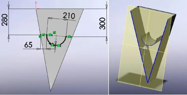
From the geometry of the bucket, the curve vane is placed at the inside of each bucket as below;
Figure 7.3: Bucket’s geometry
The water flow from the upper lake shall affect the corresponding change in the momentum.
According to Newton’s second law; the force is required to produce changes in momentum which will proportional to the rate of change of the momentum that can be expressed by;
F = ( vṁ f – vi ) (17)
Where ṁis the mass flow rate, vf is the velocity of wheel and vi is the velocity of water. The mass flow rate
can be related to continuity equation as
ṁ = ρAv (18)
= 321.07 m3/s
F = ( vṁ f – vi )
= ρAv ( vf – vi )
= 321.07(5.235 – 10.22) = 1600.53 N
The resultant force for the input analysis of both on weight of water in the bucket and the force exerted on the curve vane can be expressed by equation (5);
R
=
√
R
2x+
R
2y R = 1711.92 NThe work input done to the system can be expressed by;
Wi =
∑∫
θiθf
R dθ
=1711.92 xπ
4
= 2318.39N7.1.3 Output data analysis
From the drawing, the mass of wheel is 4640 kg
Using equation (8), the angular acceleration of the wheel can be calculated as
follows:-α =
t
2−¿t1ω
2−¿ω1¿
¿
=
10−8
840
= 2.38 x 10⁻³ rad/s2where α is the angular displacement and ω is the angular velocity at a given time. With the angular acceleration known, the moment of inertia can be calculated using equation (11),
I =
∫
r
2dm
= mr2= 4640 x (5)2 = 116000 m4
Torque can be determined by equation (12),
τ = I α = 116000 x 2.38x10-3 = 276.08 Nm
Therefore the work output , Wo =
τ
(
θ
f−
θ
i)= 276.08 x 2π
= 1735 Nm
7.1.4 Performance analysis
The mechanical efficiency ε is the effectiveness of the mechanical system to do the work can be expressed by
equation (15), ε =
W
oW
i;
1735
International Conference and Exhibition on Sustainable Energy and Advanced Materials (ICE SEAM 2011) Solo-Indonesia. October 3-4, 2011.
The mechanical efficiency of water wheel must be achieved 70% to 95% of efficiency. The UTeM’s water wheel is in the range of mechanical efficiency and further improvement is possible.
7.2 Computational Simulation Analysis
The simulation result after is achieved after computer run the iteration of solution until 78 times. The result of the simulation is converged where the solution of the iteration is being solved.
Figure 7.4: Converged iteration
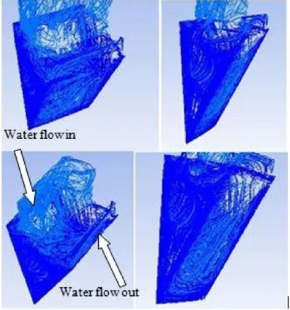
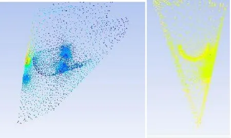
Basically, there are two type of condition that being analyze where the first condition is when the water flow enter the bucket at middle of water wheel. The computer simulation is done in order to identify the pattern of water flow.
Figure 7.5: Water flow simulation in and out of bucket
The turbulence occurs at the curve vane when the water flows into the bucket. This turbulence occurs till the bottom of the bucket. Most of turbulence occurs at the curve vane where it can generate extra force in order to rotate the bucket. There are effects of force beside the weight of water at the beginning of the water flow into the bucket. The effect might be larger if the water flow at high speed occur when the water level at the upper upstream lake is high especially during rainy days. During normal climate condition the effect is quite low.
of impact from the high speed of water jet is being exerted at the curve vane.
Figure 7.6: Velocity and pressure of water jet at strike curcved vane
8. Conclusion
The existing UTeM’s water wheel at the Durian Tunggal campus has met the acceptable mechanical performance efficiency which is 74.85%. This mechanical performance efficiency is within the range of acceptable performance of water wheel which is between 70% to 95%. Since there is opportunity for improvement in term of water wheel efficiency, several aspect of improvement needs to be identified in order to enhance the overall performance of UTeM’s water wheel.
The consideration aspect for improvement was identified from the existing UTeM’s water wheel design and operations. The UTeM’s water wheel can be improved and the suggestions for improvement are in areas of;
Water flow system
Water wheel design
Energy conversion control
Transformer
Energy storage
d) Water flow system
International Conference and Exhibition on Sustainable Energy and Advanced Materials (ICE SEAM 2011) Solo-Indonesia. October 3-4, 2011.
Figure 8.1: Pipeline at dam
The aspect of improvement for the water flow system had been indentified. The water flow system can be improved at inlet and outlet of the pipeline. Since the water would flow into the main pipe when the water level in average, it is necessary to design the main pipe located at the bottom of the dam or at the lower level. This is necessary in order to supply continuous flow of water the wheel. This could result to the rotation of wheel although the water in the upper lake is low.
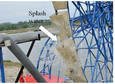
Figure 8.2: Splash water at main pipeline
The other aspect of improvement of water flow system is outlet of the pipeline. The water flow at the main especially at the high level of water can cause the water splash before entering the wheel bucket. The water splash would waste the water as it is important to fill up the bucket in order to rotate the wheel. The water splash occurs because the outlet of the main pipe is design slightly below the wheel center. The improvement of this defect can be carried out by designing the outlet pipe end curving towards the opening of the bucket. This would result to the water flow enter the bucket smoothly.
8.1 Water wheel design
light weight of the structure is another advantage of UTeM’s water wheel.
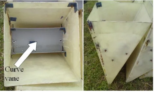
The improvement of UTeM’s water wheel can be done by manipulating the bucket shape. The UTeM’s water wheel has 32 bucket that located around the wheel. These buckets are of light weight materials and easy to manufacture.
Figure 8.3: Bucket with curve vane
The bucket design is the important aspect needs to consider in order to improve the performance of the water wheel. The bucket has large influence in the rotation of the water wheel. The good design of water wheel’s bucket is that it can carry high volume of water in order to give max weight. This weight of water is important in order to generate more torque to the water wheel. Besides that, the bucket should discharge the water from the bucket smoothly when enter the transition region of kinetic energy to potential of wheel rotation.
The curve vane of the water wheel of the water wheel is another advantage where it can assist the rotation of water wheel. The improvement of the curve vane can be made by locating the curve vane at the proper angle. The curve vane should located at the tangent of the rotation of water wheel in order to have maximum force exerted that can give 100% tangential moment instead of mixed up with radial moment.
International Conference and Exhibition on Sustainable Energy and Advanced Materials (ICE SEAM 2011) Solo-Indonesia. October 3-4, 2011.
The other factor that can consider is design of curve vane. The curve vane can be redesign by expand their function. The main function of the curve vane is to provide force when water strike to it. Besides that, the curve cave also can be design to resist water flow out of the bucket. As the result, the volume of the water flow out of the bucket can be reduced. It must be remembered that the volume of water should remain in the bucket only at the energy conversion that from potential energy to kinetic energy.
Figure 8.5 : Curve vane resist the water discharging
Reference
1. History of Hydropower, (2008). Retrieved on 1st August 2010, from
http://www1.eere.energy.gov/windandhydro/hydro_history.html
2. Introduction TO Water Wheels. Retrieved on 1st August 2010, from
http://www.reuk.co.uk/Introduction-to-Water-Wheels.htm
3. Donners,K., Waelkens, M., Deckers, J., (2002), Water Mills in The Area of Sagolassos; A Disappearing Ancient Technology, Antolia Study 52 : pp1 -17
4. Water Wheel. Retrieved in 2nd August 2010 from
http://www.puddleandpond.com/water_wheels/water-wheel-history.htm
5. Micro Power Development. Retrieved on 23rd September 2010, from http://roslank.com/minihydro.htm
6. Renewable Energy and Kyoto Protocol: Adoption in Malaysia. Retrieved on 24th Sept 2010 from
http://publicweb.unimap.edu.my/~ppks/home/index.php/news/articles
7. Green, Kevin (2000). Technological Innovation and Economic Progress in the Ancient World. M.I. Finley Reconsidered. The Economic History Review 53 (1) : 29-59
8. Lucas, A.R. (2005). Industrial Milling in The Ancient and Medieval World: A survey of the Evidence for an Industrial Revolution in Medieval Europe. Journal of Technology and Culture 46 (1) .pp 1-30
9. Matthews, S.,(2008). Harnessing the Collywobbleys Hydropower. South African Journal – Water Wheel, Vol 7, Issue 6, Nov/Dec, pp 22-24
10. Columbia Encyclopedia 2007. 6th Edition, Columbia University Press.
11. Wikanda,Orjan (2000). The Water Mill. Handbook of Ancient Water Technology, Technology Change in History, 2. Leiden: Bill, pp 371-400, ISBN 90-04-11123-9
12. Wilson, Andrew (1995), Water–Power in North Africa and The Development of The Horizontal Water-Wheel. Journal of Roman Acheology 8: pp 499 -510
13.Observation Method. Retrieved on 2nd Oct 2010 from
![Figure 2.2 Undershot wheel [9]](https://thumb-ap.123doks.com/thumbv2/123dok/580516.68990/4.595.192.380.77.222/figure-undershot-wheel.webp)
![Figure 2.3 Overshot wheel[9]](https://thumb-ap.123doks.com/thumbv2/123dok/580516.68990/5.595.182.412.304.469/figure-overshot-wheel.webp)
![Figure 2.4 Breastshot wheel[9]](https://thumb-ap.123doks.com/thumbv2/123dok/580516.68990/6.595.193.405.587.731/figure-breastshot-wheel.webp)