STRUCTURAL DESIGN OF TANGCITY MALL TANGERANG
USING SPECIAL MOMENT RESISTING FRAME
Final Project
By :
DONI PUTRA PRATAMA
Student Number: 05 13 12213
ATMA JAYA YOGYAKARTA UNIVERSITY
Faculty of Engineering
Department of Civil Engineering
International S1 Program
For each new morning with its light,
For rest and shelter of the night,
For health and food, for love and friends,
For everything Thy goodness sends.
This Final Project Has Been Dedicated To:
My Savior and Redeemer, Jesus Christ
My Beloved Father and Mother
My Little Brothers, Davin and William
v
PREFACE
First and foremost, I would like to thank God for His blessing, so that I could prepare and finish this final project report. This report was made to finish the S1 degree at Faculty of Engineering, Department of Civil Engineering, Atma Jaya University Yogyakarta.
In this final project, I redesign “Tangcity Mall Tangerang” building by using software ETABS non linier version 9.70 and SAP2000 V14. It is also designed based on SNI 2002.
I would like to express my gratitude for:
1. DR. Ir. Ade Lisantono, M.Eng, as the Dean of Engineering Faculty, University of Atma Jaya Yogyakarta.
2. Ir. Y. Lulie, MT., as the Coordinator of International Program, University of Atma Jaya Yogyakarta.
3. Prof. Yoyong Arfiadi, M. Eng, PhD as my final project’s advisor who has given me guidance and knowledge in civil engineering and also given me a will and motivation to complete this final project.
4. Ir. Junaedi Utomo, M.Eng., as the head of Civil Engineering Department, University of Atma Jaya Yogyakarta.
5. Mas Wiko, as the administration staff of International Civil Engineering Program, University of Atma Jaya Yogyakarta who has given me information and help for the administration requirements and stuffs.
6. My Father, Mother, My Little Brothers, Davin and William who always give me support and motivation.
vi
I realized that, this report has many mistakes. I openly accept all arguments and critiques from all of the readers so I can make my final project better. Finally, I hope that this final project can give benefit to the readers. Thank you and please enjoy reading my final project.
Yogyakarta, February 2011
vii
CONTENTS
COVER ... i
APPROVAL ... ii
DEDICATION SHEET ... iv
PREFACE ... v
CONTENTS ... vii
TABLE CONTENTS ... xii
FIGURE CONTENTS ... xiii
APPENDIX CONTENTS ... xv
ABSTRACT ... xvi
CHAPTER I. INTRODUCTION ... 1
1.1. General Background... 1
1.2. Problem Statement ... 2
1.3. Problem Limitations ... 2
1.4. Objective ... 3
1.5. Function ... 4
CHAPTER II. LITERATURE REVIEW ... 5
2.1. Concrete Slab ... 6
2.2. Beam ... 6
2.3. Column ... 7
2.4. Foundation ... 8
viii
3.1. Loading Analysis ... 10
3.2. Earthquake Design ... 11
3.3. Slab Design ... 12
3.4. Stair Design ... 14
3.5. Beam Design ... 14
3.5.1. Longitudinal Reinforcement ... 14
3.5.2. Shear Reinforcement ... 16
3.5.3. Torsion Reinforcement ... 17
3.6. Column Design ... 18
3.6.1. Longitudinal Reinforcement ... 18
3.6.2. Shear Reinforcement ... 19
3.7. Pile Foundation Design ... 20
CHAPTER IV.STRUCTURAL ELEMENT DIMENSION ESTIMATION ... 24
4.1. Estimation ... 24
4.2. Beam Estimation ... 24
4.3. Slab Thickness Estimation ... 27
4.4. Column Estimation ... 34
4.4.1. Calculation of Dead Load and Live Load ... 34
4.4.2. Estimation of Column I-3 ... 35
4.4.3. Estimation of Column J-1 ... 47
CHAPTER V. SEISMIC DESIGN ... 60
ix
5.2. Importance Factor I ... 60
5.3. Natural Period ... 60
5.4. Seismic Response Factor C1 5.5. Seismic Response Factor R ... 61
... 60
5.6. Distribution of Fi 5.7. T Reyleigh Analysis ... 63
... 62
5.8. Service Story Drift ... 65
5.9. Ultimate Story Drift ... 67
CHAPTER VI. STRUCTURAL ANALYSIS ... 70
6.1. Stairs Design ... 70
6.1.1. Dimension of Stairs ... 70
6.1.2. Stairs Loading ... 72
6.1.3. Reinforcement in Stairs Slab and Landing Slab ... 73
6.1.3.1. Midspan Reinforcement ... 74
6.1.3.2. Edge Reinforcement ... 75
6.1.3.3. Shrinkage Reinforcement ... 76
6.1.3.4. Control Against Shear ... 77
6.1.4. Reinforcement in Landing Beam ... 77
6.1.4.1. Edge Reinforcement ... 78
6.1.4.2. Midspan Reinforcement ... 80
6.2. Slab Design ... 83
6.2.1. Reinforcement in X direction ... 84
x
6.2.3. Control Against Shear ... 87
6.2.4. Shrinkage Reinforcement ... 87
6.3. Beam Design ... 88
6.3.1. Flexural Reinforcement ... 88
6.3.1.1. Condition I:Left Support (Negative Moment) ... 89
6.3.1.2. Condition II:Left Support (Positive Moment) ... 90
6.3.1.3. Condition III:Right Support (Negative Moment) ... 92
6.3.1.4. Condition IV:Right Support (Positive Moment) ... 93
6.3.1.5. Condition V:Middle Bottom (Positive Moment) ... 94
6.3.1.6. Condition VI:Middle Top (Negative Moment) ... 96
6.3.2. Moment Capacity ... 98
6.3.2.1. Positive Moment Capacity... 99
6.3.2.2. Negative Moment Capacity ... 103
6.3.3. Shear Reinforcement ... 107
6.3.3.1. Shear Reinforcement at Plastic Hinge ... 108
6.3.3.2. Shear Reinforcement at Outside Plastic Hinge... 110
6.3.4. Torsion Reinforcement ... 111
6.3.4.1. In Plastic Hinge ... 113
6.3.4.2. Outside Plastic Hinge ... 115
6.3.4.3. Additional Longitudinal Reinforcement ... 117
6.4. Column Design ... 120
6.4.1. Longitudinal Reinforcement ... 120
xi
6.4.1.2. Searching for Moment Caused by Earthquake ... 124
6.4.1.3. Searching for Moment Capacity ... 128
6.4.2. Shear Reinforcement ... 129
6.4.3. Beam-Column Connection ... 135
6.5. Retaining Wall Design ... 137
6.5.1. Dimension of Retaining Wall ... 137
6.5.2. Soil Data ... 138
6.5.3. Retaining Wall Stability ... 139
6.5.4. Retaining Wall Reinforcement... 144
6.6. Bored Pile Foundation Design ... 148
6.6.1. Foundation Loading ... 148
6.6.2. Amount of Pile Needed ... 151
6.6.3. Controlling The Reaction of Each Pile ... 153
6.6.4. Shear Analysis of Foundation ... 154
6.6.5. Control Against Two-way Shear ... 156
6.6.6. Control of Transferring Column Loading To Foundation ... 157
6.6.7. Pile Cap Reinforcement ... 158
6.6.8. Bored Pile Reinforcement ... 159
CHAPTER VII. CONCLUSIONS AND SUGGESTIONS ... 161
7.1. Conclusions ... 161
7.2. Suggestions ... 162
REFERENCES ... 164
xii
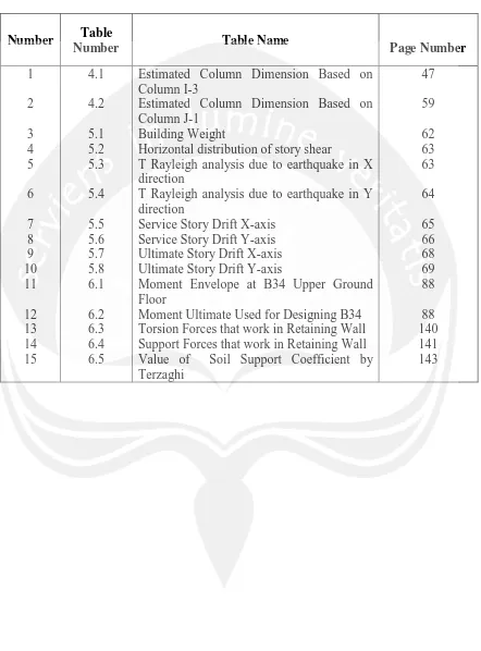
TABLE CONTENTS Number Table
Number Table Name Page Number
1
Estimated Column Dimension Based on Column I-3
Estimated Column Dimension Based on Column J-1
Building Weight
Horizontal distribution of story shear
T Rayleigh analysis due to earthquake in X direction
T Rayleigh analysis due to earthquake in Y direction
Service Story Drift X-axis Service Story Drift Y-axis Ultimate Story Drift X-axis Ultimate Story Drift Y-axis
Moment Envelope at B34 Upper Ground Floor
xiii
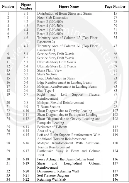
FIGURE CONTENTS Number Figure
Number Figure Name Page Number
1
Distribution of Beam Stress and Strain Floor Slab Dimension
Beam 2 (300/600) Beam 4 (300/500) Beam 1 (300/600) Beam 3 (300/600)
Tributary Area of Column I-3 (Top Floor – Basement 2)
Tributary Area of Column J-1 (Top Floor – Basement 2)
Service Story Drift X-axis Service Story Drift Y-axis Ultimate Story Drift X-axis Ultimate Story Drift Y-axis Stairs Plain View
Stairs Section
Load Distribution in Stairs
Edge Reinforcement in Landing Beam Midspan Reinforcement in Landing Beam Slab Type 4
Right and Left Support Flexural Reinforcement
Midspan Flexural Reinforcement T-Beam Section
Shear Diagram due to Gravity Loading Shear Diagram due to Earthquake Loading Shear Diagram due to Gravity Loading and Eartquake Loading
Perimeter of T-Beam Area of A
Left and Right Support Reinforcement With Additional Torsion Reinforcement
oh
Midspan Reinforcement With Additional Torsion Reinforcement
Earthquake Sway in Beam and Column Joint
Force Acting in the Beam-Column Joint
Shear and Longitudinal Column Reinforcement
Dimension of Retaining Wall Soil Pressure Diagram Retaining Wall Slab
xiv 35
36 37 38
6.23 6.24 6.25 6.26
Plan of Bore Pile Arrangement Section of Bore Pile Arrangement Loading Area for Two-way Shear Plan of Pile Cap
xv
APPENDIX CONTENS
Number Appendix Name Page Number
1
Appendix A
Building Story Weight Comparison Stairs Output Data
Column Output Data Beam Output Data
Beam Moment Release Output Data Foundation/Base Output Data Mod-Nod Interaction Diagram eod-Nod Interaction Diagram
Appendix B
Beam Reinforcement Detail Column Reinforcement Detail
Floor Slab and Roof Slab Reinforcement Detail Stairs Reinforcement Detail
Retaining Wall Reinforcement Detail
Bored Pile Foundation Reinforcement Detail Building Layout (Basement 2 Floor, Basement 1 Floor and Lower Ground Floor)
Building Layout (Ground Floor)
Building Layout (Upper Ground Floor and 1st Building Layout (2
Floor)
nd
Building Layout (3
Floor) rd
Building Layout (Top Floor) Floor) 3D Building Layout 1 3D Building Layout 2 Soil Investigation Data
xvi
ABSTRACT
STRUCTURAL DESIGN OF TANGCITY MALL USING SPECIAL MOMENT RESISTING FRAME, Doni Putra Pratama, Student Number: 12213, International Civil Engineering, Atma Jaya Yogyakarta University.
In earthquake prone area, buildings have to be designed according to the criteria specified based on earthquake loading code. This final project will consider Tangcity Mall building which located in Tangerang. This building will be designed based on SNI 03 2847 - 2002 and SNI 03 1729 -2002. This building will be considered as Special Moment Resisting Frame (SMRF) system and using concrete quality fc’ = 30MPa and steel quality fy = 400MPa for steel that has more than 12mm diameter in size and fy = 240MPa for steel that has less or equal 12mm diameter in size.
In analyzing Tangcity Mall building, ETABS non linear and SAP2000 were used to obtain internal forces of the structure and stairs. For columns design interaction diagram of Mod-Nod and eod-Nod
For the seismic design, the natural period did not fulfill the requirement but considering the story drift and the T-rayleigh are okay, so the building is considered okay. V static is used because V dynamic is less than 0.8 x V static.
were used in order to obtain the longitudinal reinforcement and for designing the shear reinforcement of beams, ETABS was used by setting all of the structure to Frame Moment Release at the start and the end.
For designing stairs, it consists of two parts, the landing beam and slabs. The calculation of the stairs and landing slab is considered as regular slab, while the calculation of beam is the same as regular beam. SAP2000 is used for analyzing the forces in the stairs. For designing slab, this final project uses two-way slabs method and the results are P10-175 in X direction and P10-200 in Y direction. As for the Beam, The beam is designed using special moment resisting frame and has the dimension of 400mm x 800mm, and using 13D25 top reinforcement 7D25 bottom reinforcement for left and right support and 4D25 top reinforcement and 6D25 bottom reinforcement for midspan. The shear design is assumed as normal beam by using Frame Moment Release in ETABS and it has 2 secondary beams forces that transferred in this main beam. For designing the column, this final project uses biaxial bending method for analyzing the column. The dimension of the column is 900mm x 900mm and using 44D25 as the longitudinal reinforcement. Retaining Wall Designing is calculated based on the soil data which has soft soil characteristic and γk=17KN/m3,φ= 30.00ο,andγw= 9.81KN/m3, it uses D19-200 for longitudinal reinforcement. The foundation is designed using bored pile. The piles have 80cm diameter and use 12D25 as the longitudinal reinforcement. The pier dimension is 4.4m x 4.4m and it has D25-150 for bottom reinforcement and D19-D25-150 for top reinforcement.


