470 PIERS Proceedings, Taipei, March 25–28, 2013
Wide Band Open Ended Air Gap RLSA Antenna at 26 GHz
Frequency Band
I. M. Ibrahim1,T. A. Rahman2,M. I. Sabran2,U. Kesavan2,and T. Purnamirza2 1Faculty of Electronics and Computer Engineering, Universiti Teknikal Malaysia Melaka, Malaysia
2Wireless Communication Centre, Universiti Teknologi Malaysia, Malaysia
Abstract—RLSA antenna is a popular candidate for many applications such as Direct Broad-cast Satellite Reception, Point to Point Microwave Link, RFID and Wimax Application. This is due to its capability of carrying high speed signal with high directivity characteristic and capabil-ity of beam steering and beam shaping. This paper will introduce the RLSA antenna designed at the frequency of 26 GHz for wireless backbone application. The antenna design was utilize open ended air gap as a separator between radiation surface and ground plane. The open air gap cavity structure normally implemented in broadband planar antennas. This structure normally provide a wide bandwidth and good return loss on the desired frequency. Therefore, an investigation of this technique and hybrid with FR4 board as a cavity material will be very interesting due to condition of easy to manufacture, lighter the antenna weight and durable. The model of RLSA antenna at 26 GHz has been simulated. The results obtained a −25 dB of reflection coefficient, 23.68 dBi of directivity gain with wide antenna bandwidth capability. This research found an opportunity of utilizing RLSA antenna concept for extreme high frequency band application.
1. INTRODUCTION
RLSA antenna was developed for Direct Broadcast Satellite application, point to point microwave link application, RFID application and Wimax application [1–3]. Many design method and tech-nique was introduced to increase the efficiency of the antenna. For point to point application, the RLSA has been designed and developed at the frequency range of 5725–5875 MHz by few re-searchers [2, 3]. The polypropylene has been used as a slow wave element in the RLSA structure. This material normally give 2.3 dielectric value [2, 3]. The other potential application for this antenna is point to point microwave link at 26 GHz frequency. Normally, parabolic antenna was used at this frequency due to minimum loss and pencil beam characteristic. The 26-GHz frequency band is allocated to broadband wireless access (BWA) in many parts of the world. The 26-GHz band offers advantages such as relatively high bandwidth resulting in a much higher bit rates avail-able to individual users when compared to frequency of around 10 GHz used typically in tropical regions [4]. It also allows the reuse of spectrum with a higher density of smaller cells resulting in a higher network capacity in urban and rural areas. These networks are particularly suited for network connection to small offices or suburban homes to high-capacity public switching and backbone networks for wireless multimedia services. Wireless information required by customers on the move includes internet, multimedia, and voice.
2. THE STRUCTURE DESIGN
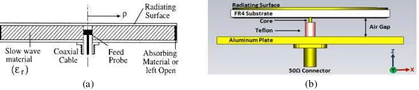
The RLSA at 26 GHz antenna for Point to Point Application was designed based on Linear Polarised Beam Squint technique. The RLSA antenna structure normally consists of a dielectric material sandwiched by copper plate. The front plate bears the radiating element while rear plate acts as a ground plane with feed element at the centre. The dielectric constant εr > 1 was chosen to suppress the grating lobes. The radiating elements are arrayed so that their radiation are added in phase along the beam direction [5, 6]. The structure of the investigated single-layer RLSA antenna is shown in Figure 1(a). The orientation of slots is in such a direction so as to transmit and receive waves of proper polarization, linear, and proper coupling inside the cavity.
In this research, the FR4 board with air gap distance to the ground plane has been introduced. The thickness of overall cavity is 3.6 mm where the thickness of open air gap is 2 mm. A 50 Ω single coaxial probe coated with Teflon is used to feed the signal into the cavity as shown in Figure 1(b). The aluminium plate is used as a platform to hold the antenna and also become a ground plane. The FR4 with 1.6 mm thickness with 5.4 permittivity value is used as a first layer substrate to the radiating surface.
Progress In Electromagnetics Research Symposium Proceedings, Taipei, March 25–28, 2013 471
(a) (b)
Figure 1: (a) Conventional structure within the cavity of RLSA antenna, (b) open ended air-gap structure of RLSA antenna.
Figure 2: The slots arrangement on the surface of Air Gap RLSA.
Figure 3: Simulated reflection coefficient of Air Gap RLSA.
adjacent slot pair #1, #2, lying along the constant direction (Φ). The 180 mm diameter of RLSA was chosen. The dielectric value has influenced the number of slots and the slots length on the surface of the antenna. The radial arrangement of slots pair has been constructed in the area of 180 mm diameter as shown in Figure 2.
3. SIMULATION RESULTS
472 PIERS Proceedings, Taipei, March 25–28, 2013
(a) (b)
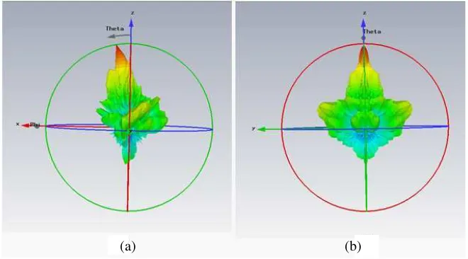
Figure 4: Simulated Radiation pattern for Air Gap RLSA, (a)E-plane, (b)H-plane.
at desired frequency. However, the result on 26 GHz is acceptable.
Figure 4 illustrates the radiated radiation pattern of the Air Gap RLSA atE-plane. The antenna
directivity gain recorded at 23.68 dBi with −10.4 dB side lobe level at E-plane and −13.8 dB at
H-plane. This antenna also provide 22 dB of front to the back lobe ratio atE-plane and 10 dB at H-plane. The main lobe squinted at 9 degree from 0 degree. The radiation pattern shows high
directivity characteristic that suitable for the target application. Low side lobe and back lobe has increase the gain of the front side of the antenna. The beamwidth of the main lobe is 6.2 degree. From the 3D pattern, it is clearly show the concentration of the radiated energy is on the main beam. In overall, the radiation pattern shown directive characteristic and have a potential to be implement at point to point application.
4. CONCLUSIONS
A model of Air Gap RLSA has been simulated using hybrid air gap and FR4 dielectric material. The 50% wide bandwidth has been recorded through this approach. A 23.68 dBi directive gain also recorded from the simulation. The 6.2 degree beamwidth of the radiation pattern is sufficient for high directional application. Since the proposed application was for Point to Point Link, this study proposed the Air Gap RLSA can be a new candidate for this application.
ACKNOWLEDGMENT
The author would like to acknowledge and express sincere appreciation to Universiti Teknologi Malaysia and Ministry of Higher Education Malaysia (MOHE) for funding this project. Appre-ciation also goes to University Teknikal Malaysia Melaka and MOHE for funding the author’s scholarship.
REFERENCES
1. Jamlos, M. F. B., T. A. Rahma, M. R. B. Kamarudin, P. Saad, O. Abdul Aziz, and M. A. Sham-sudin, “Adaptive beam steering of RLSA antenna with RFID technology,” Progress In Elec-tromagnetics Research, Vol. 108, 65–80, 2010.
2. Ibrahim, I. M., T. A. Rahman, P. S. Wei, and J. Ahmad, “A study on effectiveness of FR4 as a dielectric material for radial line slot array antenna for wireless backhaul application,”
The 17th Asia-Pacific Conference on Communications (APCC 2011), Sutera Harbour Resort, Kota Kinabalu, Sabah, Malaysia, Oct. 2–5, 2011.
3. Ibrahim, I. M., A. Riduan, A. R. Tharek, and A. Hasnain, “Beam squinted radial line slot array antenna (RLSA) design for point-to-point WLAN application,” Asia Pacific Applied Electromagnetics Conference (APACE 2007), Melaka, Malaysia, Dec. 4–6, 2007.
Progress In Electromagnetics Research Symposium Proceedings, Taipei, March 25–28, 2013 473
5. Ando, M., K. Sakurai, and N. Goto, “Characteristics of a radial line slot antenna for 12 GHz band satellite TV reception,” IEEE Transactions on Antennas and Propagation, Vol. 34, No. 10, 1269–1272, Oct. 1986.