Kinematic synthesis of planar, shape-changing, rigid body
mechanisms for design pro
fi
les with signi
fi
cant differences in
arc length
Shamsul A. Shamsudin
a, Andrew P. Murray
b, David H. Myszka
b,⁎
, James P. Schmiedeler
caFaculty of Mechanical Engineering, Universiti Teknikal, Melaka, Malaysia
bDepartment of Mechanical and Aerospace Engineering, University of Dayton, Dayton, OH 45469, USA cDepartment of Aerospace and Mechanical Engineering, University of Notre Dame, Notre Dame, IN 46556, USA
a r t i c l e
i n f o
a b s t r a c t
Article history:
Received 13 November 2012 Received in revised form 15 July 2013 Accepted 5 August 2013
Available online 6 September 2013
This paper presents a kinematic procedure to synthesize planar mechanisms capable of approximating a shape change defined by a general set of curves. These“morphing curves,” referred to as design profiles, differ from each other by a combination of displacement in the plane, shape variation, and notable differences in arc length. Where previous rigid-body shape-change work focused on mechanisms composed of rigid links and revolute joints to approximate curves of roughly equal arc length, this work introduces prismatic joints into the mechanisms in order to produce the different desired arc lengths. A method is presented to iteratively search along the profiles for locations that are best suited for prismatic joints. The result of this methodology is the creation of a chain of rigid bodies connected by revolute and prismatic joints that can approximate a set of design profiles.
© 2013 Elsevier Ltd. All rights reserved. Keywords:
Similarity transformation Image registration Rigid body mechanisms Shape-change Prismatic joints
1. Introduction
The focus of much study has been on shape morphing aircraft wings that increase performance over a range of flight conditions[1,2], and most of the design work has centered on changing between wing profiles of similar arc length[3–5]. The fundamentals of aerodynamics suggest, however, that lift and drag can be significantly altered with a change in camber and chord[6]. That is, for high lift situations (e.g., approach, landing, and climb), a higher camber and longer absolute chord are desirable, whereas for efficient cruising, a lower camber and shorter chord are desirable.
Many other mechanical systems benefit from the capacity to vary between specific shapes in a controlled manner. In addition to airfoils, shape changing systems have been used in other flow-field applications such as active boat hulls [7]. Advances in electro-optics resulting from shape change include active aperture antennas[8]and deformable mirrors[9]. Automotive convertible roofs[10]and portable performance stages[11]involve shape changes in structural applications. In manufacturing, robotic grippers
[12]are designed to move between prescribed shapes. Altering an extruded plastic profile by sliding segments of the die orifice in a controlled manner[13]may also be considered shape change. As with airfoils, many of these example application areas could have optimal designs that require relaxation of the constraint that the various morphing shapes all be of identical arc length.
Shape change may be accomplished by using compliant mechanisms, which can be designed in a manner similar to rigid-body mechanisms[14]. Without hinges, though, compliant mechanisms have the advantage of providing a smooth morphing boundary without discontinuities. Lu and Kota[15]used optimization algorithms to search discrete characteristics of a topology to best utilize compliant mechanisms to control the change of shape of a parabolic antenna. Moon[16]used compliant mechanisms to
⁎ Corresponding author. Tel.: +1 937 229 2968; fax: +1 937 229 4766.
E-mail addresses:[email protected](S.A. Shamsudin),[email protected](A.P. Murray),[email protected](D.H. Myszka),
[email protected](J.P. Schmiedeler).
0094-114X/$–see front matter © 2013 Elsevier Ltd. All rights reserved. http://dx.doi.org/10.1016/j.mechmachtheory.2013.08.007
Contents lists available atScienceDirect
Mechanism and Machine Theory
approximate the shape of a human finger during gripping motion, and Mohd Zubir et al. [17] similarly used a compliant mechanism for a microgripper. Limaye et al.[18]incorporated compliant kits of beams and connectors to generate a morphing aircraft wing. The displacement achievable with a compliant mechanism, however, is limited by the elastic properties of its composing material, so it is quite difficult to accommodate shape changes involving significant differences in arc length with a compliant mechanism.
For shape changes accomplished with rigid-body mechanisms, the edge geometries of some links are chosen to approximate a set of specific shapes[19]. A formalized process for creating such rigid-body shape-change mechanisms has been developed for shapes, called design profiles, characterized by open curves[20], closed curves[21], and curves with fixed endpoints[22]. In all cases, the prescribed profiles are constrained to have nearly constant arc length. The developments presented in this paper enable a chain of rigid bodies to approximate design profiles that exhibit significant differences in arc length.
The general process of rigid-body, shape-changing mechanism design is as follows. The problem is posed by specifying a set of design profiles, such as airfoil profiles for loiter and attack modes. The synthesis process begins by representing each of the design profiles in a standardized manner such that comparisons can be made among them. This standardized representation is a coordinated set of points on the design profile defining a piecewise curve that is called the target profile. The design process continues with a segmentation phase that creates segments, which are generated in shape and length so that they form rigid links that approximate corresponding portions on each target profile. To complete the synthesis, a mechanization phase adds binary links to each segment in order to achieve a lower degree-of-freedom (DOF) linkage. A system with fewer DOF is commonly preferred for simplicity[23]and ease of control[24,25]. Although this general process of designing a rigid-body, shape-changing mechanism remains true for this work, substantial changes are needed to allow for significant differences in arc length.
Target profiles were originally defined in [20] such that all contained the same number of points. This definition is fundamentally lacking for profiles of different arc lengths because the large variations in the distance between consecutive points complicate the comparison of profile shapes. To properly compare various length profiles, the target profile definition has been changed to produce a nearly constant distance between consecutive points on each profile, resulting in a different number of points on each. During the segmentation phase, the constant arc length segment is preserved from the preceding methodology. Necessitated by various arc lengths, however, a new type of segment has been developed that includes a prismatic joint allowing the segment to change length in matching the set of design profiles. Additionally, the prior segmentation methodology has been transformed to iteratively search for locations along the profiles best suited for the prismatic joints. Lastly, a new process is outlined to detect revolute joints exhibiting only minimal motion in matching the target profiles. A revolute joint identified in this way is eliminated by combining the adjoining segments to reduce mechanism complexity[23]. If either or both of the segments includes a prismatic joint, combining them in this fashion introduces a third, compound segment type. Should neither segment contain a prismatic joint, an alternate strategy is used, detailed inSection 6, as eliminating this joint may introduce unnecessary error.
a
b
c
The remainder of the paper is organized as follows.Section 2addresses a new process for converting design profiles into target profiles having similar spacing between defining points.Section 3presents a process for segmenting regions along target profiles that will form the rigid bodies.Section 4discusses the process for assessing the segmentation error and a method for adjusting the segments to improve profile matching.Section 5presents the method to join the chain with revolute joints, andSection 6
discusses a process to merge segments when the associated revolute joint exhibits minimal rotation. Section 7 reviews mechanization, and examples are given inSection 8.
2. Design and target profiles
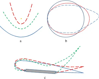
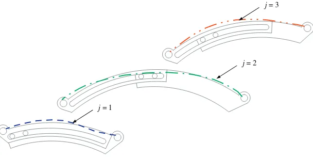
The shape-change problem is posed by specifying a set ofpdesign profiles that represent the different shapes to be attained by the mechanism. In prior work, Murray et al.[20]defined a design profilejas an ordered set ofNjpoints for which the arc length between any two can be determined. This definition remains valid for profiles with different arc length.Fig. 1shows the three types of design profiles considered: open, closed, and fixed-end profiles. While the illustrative examples shown in this paper are for the open profile case, this research establishes a process to form a chain of rigid links to approximate any of these types of profiles.
Given the definition of design profiles, they may be viewed as being piecewise linear[26,27]. A piece is the line segment connecting two contiguous points on a profile. Theithpoint on thejthdesign profile is designated aji;bji
T
. The length of theith
piece on thejthdesign profile is
cji¼
ffiffiffiffiffiffiffiffiffiffiffiffiffiffiffiffiffiffiffiffiffiffiffiffiffiffiffiffiffiffiffiffiffiffiffiffiffiffiffiffiffiffiffiffiffiffiffiffiffiffiffiffiffiffiffiffiffiffiffi ajiþ1−aji
2
þ bjiþ1−bji
2
r
; ð1Þ
and the arc length of the entirejthdesign profile is
Cj¼ X Nj−1
i¼1
cji: ð2Þ
The design profiles may be defined by any number of points spaced at various intervals, producing a wide range ofcji. A target profile is a curve that represents a particular design profile. Sets of target profiles have common features so that groups of contiguous points can be compared among all profiles in order to form a suitable chain of rigid bodies that when repositioned will approximate all design profiles. In earlier work[20,21], the design profiles were assumed to be of roughly equal arc lengths,C1≈C2≈…≈Cp. In that case, each target profile can be formed by distributing the samennumber of defining points equally along the corresponding design profile. The target profile becomes a piecewise linear curve composed of pieces with roughly the same length,cji≈ckl;∀i;j;k;l. Constant piece lengths allow for identification of corresponding points on each target profile.
The general profiles discussed in this paper may possess large differences in arc length. Using the same number of points on different length profiles, as done in previous work, would result in different piece lengths and contaminate the shape comparisons among groupings of contiguous points. In order to produce a constant piece length, the conversion scheme from design to target profiles must be modified to allow for a different number of points on each target profile. By specifying a desired piece lengthsd, the number of piecesmjon profilejcan be determined. Smaller values ofsdwill produce more pieces and typically result in smaller variations between the design and target profiles.
The number of pieces must be an integer, and an initial value is calculated as
mj¼
⌈
Cj sd⌉
; ð3Þ
where⌈Cj/sd⌉represents the ceiling function, the smallest integer not less thanCj/sd. Provisional target profiles are generated by
distributingnjpoints at increments ofCj/mjalong thejthdesign profile. A distribution of target profile points along a design profile
j=1
)
,
(
x
11y
11)
,
(
x
12y
12)
,
(
x
13y
13)
,
(
5 5 1
1
y
x
)
,
(
x
14y
14 21
s
C1/m11
1
s
3
1
s
41
s
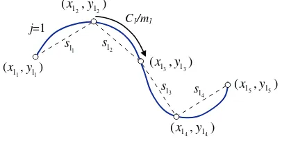
Fig. 2.Design profile (solid) with an approximating target profile (dashed) where points are positioned to give a constant arc length along the design profile.
is shown inFig. 2. Thejthtarget profile becomes a piecewise linear curve connecting the ordered set of pointszji¼ xji;yji n oT
,i= 1,...,
nj. The length of theithlinear piece on thejthtarget profile is
sji¼ zjiþ1−zji
¼
ffiffiffiffiffiffiffiffiffiffiffiffiffiffiffiffiffiffiffiffiffiffiffiffiffiffiffiffiffiffiffiffiffiffiffiffiffiffiffiffiffiffiffiffiffiffiffiffiffiffiffiffiffiffiffiffiffiffi xjiþ1−xji
2
þ yjiþ1−yji
2
r
: ð4Þ
The corresponding number of points on target profilejisnj=mj+ 1.
For a provisional target profile, the piece lengthssji≤sd, as Eq.(3)generates slightly more segments than would exactly match the profile using the piece lengthsd. Moreover, any curvature of the design profile results in piece lengths shorter thansd, as seen
inFig. 2. That is, a piece lengthsji¼sdonly whensddivides exactly intoCjpieces and the design profile has a zero curvature portion long enough to include the entire piece. The average piece length for thejthprofile is
sj¼
1
mj X nj−1
i¼1
sji 0 @
1
A: ð5Þ
As the provisional target profile is constructed to (potentially) have too many pieces to accurately achievesd, the likely
scenario is that fewer pieces will produce a value ofsj closer tosd. An error representing the difference between the average
segment length and desired segment length is calculated assj¼ sd−sj
. Decreasingnjby 1 and redistributing points along the design profile creates a new target profile. Points are removed untilnj=nj∗(and correspondingly,mj=mj∗), the number of points minimizessj. The end result is the fewestnj
∗points are used to construct thejthtarget profile such that all linear piece lengths are
approximately equal to the desired segment length. Desirable target profiles are those with the fewest pieces that achieve the accuracy needed to satisfactorily represent the original design profiles. The more pieces used in a set of target profiles, the closer the approximation of the design profiles. Conversely, as the calculations presented in the later sections are dependent on this number, having fewer pieces reduces computation time.
After eachmj∗is established, the total length of thejthtarget profile is calculated as
Sj¼ Xmj
i¼1
sji: ð6Þ
Applying this process to all design profiles,ptarget profiles are constructed such that all linear pieces have lengths that are approximately equal tosd. The average length of allmj∗linear pieces on allpprofiles is
sm¼ Xp
j¼1 Sj Xp
j¼1 m
j
: ð7Þ
If the representation of the design profiles lacks the desired accuracy, a smaller desired piece length may be used to increase the number of points defining the target profiles.
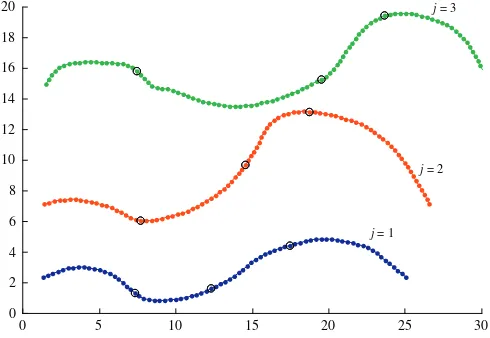
Three target profiles are shown inFig. 3. The lengths of the design profiles areC1= 26.1738,C2= 31.0847, andC3= 34.4737. For a desired piece length ofsd= 0.35, the target profiles havem1∗= 76,m2∗= 90, andm3∗= 99 pieces. The average piece length
0 5 10 15 20 25 30
0 2 4 6 8 10 12 14 16 18 20
j = 1 j = 2
j = 3
issm¼0:3499 and the lengths of the target profiles areS1= 26.1669,S2= 31.0760, andS3= 34.4562. AlthoughS1/C1= 0.9997,
S2/C2= 0.9997, andS3/C3= 0.9995 in this example, the heuristic in this work is to setsdsuch thatSi/Ci≥0.99 for all profiles in
the set unless the design problem dictates a specific accuracy. Values are reported in this initial example to four decimal places to highlight the minor differences between design and target profile lengths and desired and achieved piece lengths. The four decimal places are not meant to indicate that these are significant figures.
3. Segmentation
After target profiles with nearly constant piece lengths have been established to adequately represent the design profiles, the rigid bodies that form the edge geometry of the profiles must be created. The segmentation process identifiesqportions, or segments, of a target profile that when repositioned will best match the corresponding portions on the other target profiles. An acceptable error in matching profiles is dependent on the application and is at the discretion of the designer.
Mean orM-segments represent a fixed length portion on the set of target profiles, as shown inFig. 4, and will be embodied by rigid revolute-revolute (RR) links. Constant curvature orC-segments consist of variable length portions on the set of profiles, shown inFig. 5, and will be embodied by a pair of rigid links forming a revolute-prismatic-revolute (RPR) chain. Once identified, the segments are created and assembled into a chain that can be moved to approximate the full set of design profiles.
When the set of design profiles have similar arc lengths, the chain of rigid-bodies that adequately approximates them may contain allM-segments. For the general case, when the design profiles have significantly different arc lengths, each target profile will have a different number of points since the pieces have roughly equal lengths. The difference in arc length is quantified by the difference in the number of pieces used in defining the target profiles. For appreciable differences, at least one of the segments must be aC-segment. As described in the following sections, the segments are created through an iterative process that reduces shape-approximating error.
3.1. Segments
Certain restrictions are placed on identifying theqgroups of points that will form segments on each of the target profiles. The number of pieces on theethsegment of thejthprofile is designatedmje, and the number of points isnje=mje+ 1. Since an
M -segment represents a single rigid link, a fundamental constraint on formingM-segments is that the number of pieces in those segments is constant across allpprofiles, i.e., if theethsegment is anM-segment,m1e =m2e=…=mpe. Since theC-segments are
used to compensate for differences in length among the profiles, the number of pieces in correspondingC-segments from different profiles will generally be different. The number of pieces in theC-segment on thejthprofile must be selected such that∑eq= 1mje=mj∗.
The points that lie on the boundary between segments are termed segmentation points, which also include the first and last points on the target profile. Points on thejthtarget profile are numbered 1 throughnj∗. The index of the segmentation point at the start of theethsegment on thejthprofile is designated askje. The index of the final point of that segment iskje+ 1. Note thatkje+ 1
is also the index of the first point on thee+ 1 segment. Thus,
k1j ¼1 j¼1;…;p ð8Þ
j = 1
j = 2
j = 3
Fig. 4.AnM-segment represents a single revolute–revolute link that corresponds to groups of equal numbered pieces on each target profile.
kej¼k e−1
j þm e−1
j ¼1þ X e−1
i¼1
mij e¼2;…;q j¼1;…;p ð9Þ
kqjþ1¼n
j j¼1;…;p: ð10Þ
The same number of segmentsqand their types (i.e.M- orC-segments) must be maintained for all profiles. A design vectorV
defines the number of segments and their types in a candidate design. As an example, V¼ M C M C½ specifies that four segments (q= 4) will be formed, with the first being anM-segment, followed by aC-segment, anM-segment and aC-segment. Currently, an a priori method to determine the bestVfor a set of design profiles is lacking. The designer can specifyVbased on intuition after inspecting the shape of the profiles, or the error minimizing process can cycle through several design vectors to attain an adequate fit to the set of target profiles. Any combination ofMandC-segments is possible. For a design withqsegments, there are 2q−1different design vectors that contain at least one
C-segment. It is noted that aC-segment represents two rigid links, while anM-segment represents one rigid link in the shape-approximating chain.
3.2. The segment matrix
Ap×qsegment matrixSMidentifies the number of pieces in each segment and is constructed consistent with the design vector. Thejthrow ofSMrepresents thejthtarget profile and contains the number of pieces for each segment on that profile. From an implementation standpoint, segments should not be so small that a physical embodiment is impractical. A minimum number of segment piecesαis defined such thatmje≥α,e= 1,…,qwherej= 1,…,p.
As an example, consider the set of three target profiles from Fig. 3 having m1∗= 76, m2∗= 90, and m3∗= 99 pieces, respectively. Based on physical constraints,α= 5 was specified. With V¼ M C M C½ , an initial segment matrix may be constructed as
SM1¼
m11 m21 m31 m41 m12 m22 m32 m42
m13 m23 m33 m43
2 6 4
3 7 5¼
15 13 9 39
15 9 9 57
15 39 9 36
2 4
3
5: ð11Þ
Since the first segment is anM-segment, the same number of pieces has been selected to be used on all profiles:mj1= 15 wherej= 1,…, 3. Similarly for the third segment,mj3= 9 wherej= 1,…, 3. BeingC-segments, all instances of the second and fourth segments do not need to have the same number of pieces. The number of pieces in the second segment is individually selected. Being the finalC-segment inV, the fourth segment will contain all remaining pieces in the profile. That is,m14= 39, such that forj= 1, 15 + 13 + 9 + 39 = 76 =m1∗, and likewise for the other profiles. The segmentation points can be calculated with Eqs.(8), (9), and (10). Forj= 1,k11= 1,k12= 16,k13= 29,k14= 38, andk15= 77. The segmentation points are indicated with black circles inFig. 3.
Once an initialSMis formulated, an iterative process creates the segments, evaluates how well they match the target profiles and adjustsSMto minimize the error. The method for creating the segments is described in the following two sub-sections. The details of the evaluation and adjustment process are explained inSection 4.
j = 1
j = 2 j = 3
Fig. 5.C-segments are variable arc length groups of pieces consisting of a different number of points on each target profile and represent a revolute–prismatic–
revolute chain.
3.3.M-segments
The process of creating an M-segment is identical to that described in Murray et al. [20]and is summarized here for completeness. The process begins by shifting all points on the segment to a common location so a single profile can be generated that approximates the shapes of all segments within the set. The first profile is selected as the common location, so each segment from the second through last profile is shifted to the first profile. Each point on theethsegment is shifted by a rigid body transformation in the plane,
Zeji¼A
e jzjiþd
e j i¼k
e
j;…;kejþ1 j¼2;…;p; ð12Þ
where
Aej¼
cosθej −sinθej
sinθej cosθej
" #
; dej¼ xej yej " #
: ð13Þ
Although a general solution for the transformation is well-established in the image registration literature[28–31], Murray et al.[20]developed a closed-form method to determineθjeandd
j
esuch that the sum of the distances between each point on
the shifted segments and the corresponding point on the reference segment is minimized. Then, a new piecewise linear curve is constructed where each point is the geometric center of the set ofpcorresponding points in the reference segmentz1iand the shifted segmentsZji. This new curve becomes theM-segment defined by points
Zemi¼ 1
p z1iþ Xp
j¼2
Zji 0
@
1
A i¼kej;…;kejþ1: ð14Þ
0 2 4 6
0 2 4 6 8 10 12 14 16 18 20
0 2 4 6
0 2 4 6 8 10 12 14 16 18 20
0 2 4 6
0 2 4
0 2 4 6
0 2 4
Mean Segment
j = 1
(
reference)
15
1 1=
m
j = 215
1 2=
m
j = 315
1 3=
m
a
b
c
d
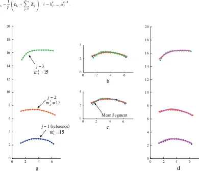
Fig. 6.(a) The first segment from each of three target profiles to be represented by one mean segment. (b) Segments 2 and 3 shifted to reference segment 1 in a distance minimizing transformation. (c) The mean segment generated as the average of the corresponding segment points. (d) The mean segment shifted back to the original segments in another distance minimizing transformation.
This M-segment represents one rigid RR link in the shape-changing chain. A second minimization process determines a rotation matrixAbejand translationbdejto shift instances of the mean segment back to profiles 2 throughpto approximate the shape of the segment on each target profile.
zeji¼ Ab
e j
−1
Zemi−db
e j
i¼kej;…;k eþ1
j j¼2;…;p: ð15Þ
The first segments from the three profiles (e= 1, j= 1, 2, 3) presented in Fig. 3are shown in Fig. 6a and shifted to distance-minimizing positions relative to the first profile inFig. 6b.Fig. 6c shows the creation of anM-segment that approximates the set, which is shifted back to each target profile inFig. 6d.
3.4.C-segments
A constant curvatureC-segment is created using discrete, signed, radius of curvature values at each point along the segment for all target profiles[27]. The radius of curvature value of thejthtarget profile at theithpoint is the radius of an arcrjithat passes throughzji and the neighboring pointszji−1andzjiþ1[32]. The radius of curvature is computed for each point on theethsegment as
rji¼
zjiþ1−zji−1
2sinθ i¼k
e
jþ1…;kejþ1−1 j¼1;…;p: ð16Þ
whereθis the angle∠zji−1zjizjiþ1[33].
A direction vectorPjiis defined such that it extends fromzji−1 tozji.
Pji¼
xji−xji−1 yji−yji−1
: ð17Þ
If the determinant Pji Pjiþ1
is positive, the radius of curvature is designated positive[34]. The mean radius of theethsegment on all profiles is
re¼Xp 1 j¼1 m
e j−1
Xp
j¼1
X keþ1
j −1
i¼ke jþ1
rji 0 @ 1 A 0 @ 1
A: ð18Þ
The curvatures of the first and last points are not included in the average. Instances of aC-segment are created by generating pointsZejialong a radiusr
eand arc length
Lej¼m e
j s e
; ð19Þ
5 10 15 20
0 2 4 6 8 10 12 14 16 18 20
5 10 15 20
0 2 4 6 8 10 12 14 16 18 20
j = 1
j = 3
j= 2
9 2 2= m 39 2 3= m 13 2 1= m
a
b
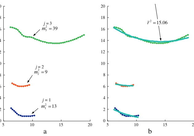
06 5 1 . 2= rFig. 7.(a) The second segment from each of three target profiles approximated with aC-segment. (b) An arc of the same radius, but varying length, approximates the segment on all profiles.
where the average length of the pieces on theethsegment on allpprofiles is
se¼X
p
j¼1 1
me j
X keþj1−1
i¼ke jþ1
sji 0 @ 1 A 0 @ 1
A: ð20Þ
As with theM-segments, instances of theC-segment are placed at each target profile in a distance minimizing transformation using Eq.(15).
Each of the second segments from the three profiles (e= 2,j= 1, 2, 3) presented inFig. 3are shown inFig. 7a with a mean piece length ofsm¼0:35 and each having a different number of pieces (m11= 13,m21= 9 andm31= 39). A mean radius is calculated asr1¼15:06, and arcs with lengths ofL11= 4.55,L21= 3.42 andL31= 13.65 are constructed and align with the profiles as shown inFig. 7b.
4. Evaluating and adjusting the segment matrix
Once instances of the segments are created as specified bySM, their shape-approximation errors are evaluated. The maximum point-to-point distance on thejthinstance of theethsegment to the corresponding point on thejthprofile is
Eej¼maxz e ji−zji
i¼kej;…;kejþ1: ð21Þ
Similar toSM, ap×qerror matrixEMorganizesEje for all segments on all profiles. Error metrics that assist in segment
adjustment include the maximum overall error,
Emax¼max E e
j e¼1;…;q j¼1;…;p; ð22Þ
the mean error of theethsegment,
Ee¼1
p Xp
j¼1
Eej; ð23Þ
and the overall mean error
E¼1
q Xq
e¼1 1
p Xp
j¼1
Eej 0 @
1
A: ð24Þ
An example of theEMthat corresponds with the profiles fromFig. 3and the initialSMof Eq.(11)is
EM1¼
E11 E21 E31 E41 E12 E22 E32 E42 E13 E23 E33 E43 2 6 4 3 7 5¼
0:10 0:32 0:04 0:43
0:15 0:19 0:03 1:37
0:19 0:46 0:06 1:50 2
4
3
5: ð25Þ
In Eq.(25),Emax= 1.50 andE¼0:40. For theM-segments,E1¼0:15 andE3¼0:04.
The number of pieces in each segment can be changed to improve the shape approximation and consequently reduceEmax. Adjustments toSMinvolve either adding, removing or preserving the number of pieces in each segment in order to balance the errors, i.e.,EmaxapproachesE. For aC-segment, eachEjeis compared toE. IfEe
jbE, the segment fits the profile better than the average
and can be lengthened to balance the error. A changeδmje= +1 is assigned to that instance of the segment, meaning that one
piece will be added. Conversely, ifEejNE, that instance of the segment has a below average fit, andδmj
e=−1 is assigned, meaning
that one piece will be removed.
Because allM-segments must be adjusted the same amount, eachEeis compared toE. IfEebE, a change is assigned to all profiles
δmje= +1,j= 1,…,p. Since a segment cannot violate the minimum number of pieces constraint, aδmje= 0 may be assigned if
mje=α. Additionally, the total number of pieces on each profile must remain the same,
Xq
e¼1
δmej¼0; j¼1;…;p: ð26Þ
As in the generation ofSM, the finalC-segment withinVis not adjusted according to its error. Instead, it is adjusted to ensure that thejthprofile retainsmj∗pieces. Hence, either no change or changes greater than one may be assigned to the instances of the
lastC-segment.
The changes are added toSMto obtain an adjustedSMwith which a new segmentation trial is conducted. The iterative process continues, assessing errors at each step in order to achieve a final segment matrix with a low point-to-point error. The iterations are stopped when the current value ofEmaxis greater than or equal to the previous five values. To avoid a local minimum, these error-reducing iterations are performed on several initialSMmatrices. The tSM associated with the lowest value ofEmaxwithin the entire error history is deemed to be the distance minimizing set of segments. These error-reducing iterations were conducted on the four-segment chain ofFig. 3and theSMof Eq.(11). The segment matrix with the lowestEmaxis
SMf ¼
19 12 14 31 19 22 14 35 19 42 14 24
2 4
3
5; ð27Þ
which resulted in an error matrix
EMf ¼
0:17 0:22 0:33 0:17
0:26 0:10 0:15 0:20
0:19 0:23 0:21 0:32 2
4
3
5: ð28Þ
The error metrics were reduced toEmax= 0.33 andE¼0:22 (fromEmax= 1.50 andE¼0:40 withSM1). The rigid-body chain associated with the initial segmentation is shown inFig. 8a, whereasFig. 8b shows the chain after the error-reducing iterations.
5. Joining the chain
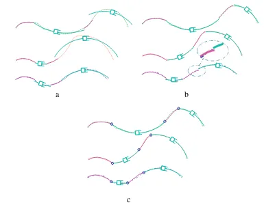
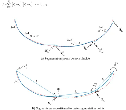
Since the segments are generated individually, the segmentation point on one segment will not typically coincide with the corresponding segmentation point on the adjoining segment. As shown inFig. 9a,zeji≠z
eþ1
ji ,∀i=kj
e,e= 2,…,qandj= 1,…,p.
Since the segments will be connected at their endpoints with revolute joints, each segment must be slightly moved from its error-minimizing position to unite the segmentation points. During this process, each profile is treated individually.
Each point on each segment of thejthprofile is relocated by
e
zeji¼eA
e jz
e jiþed
e
j; i¼1;…;nj; e¼1;…;mj; ð29Þ
a
b
c
Fig. 8.A rigid-body chain that approximates the target profiles. (a) The chain after the initial segmentation matrix:Emax= 1.50. (b) The chain after the
error-reducing iterations:Emax= 0.33. The inset illustrates that segmentation points are not coincident. (c) The joining process unites segmentation points, yet
increases the error toEmax= 0.34.
where
e
Aej¼
coseθej −sineθej
sineθej coseθej
" #
; de e j¼
e xej e yej " #
:
The endpoints of adjacent segments must be coincident, which provides the principal constraint,
ezeji¼ez
eþ1
ji ¼ezji ∀ i¼k
e
j; e¼2;…;q j¼1;…;p: ð30Þ
For closed-loop target profiles, additional constraints include
Xq
e¼1
lecoseθ e j¼0;
Xq
e¼1
lesineθ e
j¼0; j¼1;…;p; ð31Þ
wherele is the length of the line segment connecting the first and last points on segmente. For fixed-end target profiles, additional constraints include
ez1j1¼zj1; ez q
jn j
¼zjn j
: ð32Þ
As in Persinger et al.[21]the segmentation points are united through a numerical optimization to determineezej1,e= 2,…,q
subject to Eq.(30), and if appropriate, Eq.(31)or Eq.(32). As shown inFig. 9b, the location of the first point on eachjthinstance of the chainez1j1, the angle of each segment instanceeθe
j, and the translationed e
j are theq+ 2 optimization variables. The objective
functionfto be minimized is the sum of the squared point-to-point distances between points on the instance of the segments and the points on thejthtarget profile,
f ¼X
ke j
i¼1
ezeji−zji h iT
e
zeji−zji
h i
e¼1;…;q: ð33Þ
e
=1
e
=2
e
=3
1 120z
2 120z
j
=1
19
1 1=
m
14
2 1=
m
10
3 1=
m
2 134z
3 134z
3 144z
1 1~
θ
3 1~
θ
2 1~
θ
1 11~
z
l
1l
2l
3 20 1~
z
34 1~
z
j
=1
a)
Segmentation points do not coincide
b)
Segments are repositioned to unite segmentation points
Fig. 9.After instances of segments are created, the segmentation points will not coincide. To merge the segmentation points and form a chain connected by revolute joints, each segment must be repositioned by adjustingez1j1andeθe.
Thefminconfunction in the optimization toolbox of MATLAB is well suited for this type of constrained nonlinear multivariable problem. The position of the segments as determined by the segmentation process generally serves as a suitable initial guess. Once optimized,ezeji;e= 2,…,q,i= 2,…,nj
∗defining the chain of rigid links joined with revolute and prismatic joints is complete. The
optimization is conducted for the other profiles as well, resulting in a rigid-body chain that can be repositioned to approximate all target profiles.
The results of the joining process for the three profiles presented inFig. 3is shown in Fig. 8c. After the error-reducing iterations onSM, the maximum point-to-point error wasEmax= 0.33. However, after shifting segments to merge segmentation points, the maximum point-to-point error increased toEmax= 0.34.
If the accuracy of the approximation is deemed unsatisfactory, the designer can return to the segmentation phase and dictate a different design vectorVor increase the number of segments. To compare alternative designs, the number of joints in the chain of rigid-bodies should be considered.M-segments represent R-R links, so they contain two joints, whereasC-segments represent R–P–R chains and contain 3 joints. Generally, a chain of rigid-bodies with a greater number of joints provides a better approximation to the profiles at the expense of greater mechanical complexity. Khan et al.[23]developed the loss of regularity index as a quantitative measure of kinematic chain complexity. From a practical perspective of constructing a mechanism, it is desirable to find a compromise between the number of joints and the error between the chain of rigid-bodies and the target profiles.
6. Compound segment types
Since the number of links in the chain increases the mechanical complexity, it is desirable to fuse some of the links together when the rotation of a revolute joint is small. To investigate the benefit of each revolute joint in the chain of rigid-bodies, the range of motion is calculated to determine whether the joint is necessary. Recall thatPjiis the direction vector that extends from
zji−1tozji. Accordingly, the direction vector that extends from the preceding point toward theethsegmentation point on thejth profile is Pjke
j
, and Pjke
jþ1
is the vector from theethsegmentation point to the next point. The relative joint angle at theeth
segmentation point is designated asσjeand is represented by the angle fromPjke j
toPjke jþ1
. Thus, the range of motion exhibited by that joint is
Δσe¼maxσej−minσel j¼1;…;p; l¼1;…;p: ð34Þ
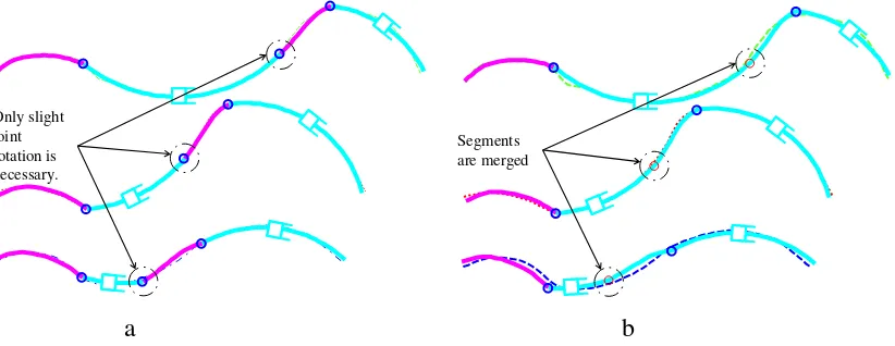
If the range of motion is smaller than a specified limit,Δσebσmin, the revolute joint motion is considered insignificant during shape approximation. That joint may be considered unnecessary and eliminated to reduce the complexity. If the revolute joint connects twoM-segments, the designer is advised to select a new design vectorVwith fewer segments. If the revolute joint connects aC-segment with either anotherC-segment or anM-segment, the joint can be eliminated, clamping the segments at the mean angle. Eliminating the joint creates a compound segment that merges the two original segments. Returning to the example profiles ofFig. 3, the reduced-error chain ofFig. 8is shown inFig. 10a. The range of motion of the 2ndrevolute joint, however, is
Δσe= 12.2°and may be considered insignificant. The segments were merged to create the chain shown inFig. 10b. Eliminating the revolute joint increased the maximum point-to-point error from Emax= 0.34 toEmax= 0.46. However, the number of segments and kinematic complexity has been reduced at a modest expense of error.
7. Mechanization
The mechanization phase involves adding rigid constraining links and joints to form a mechanism that smoothly transitions the shape approximating chain between the target profiles with a limited number of actuators. In many applications, the reduced cost and control requirements of fewer actuators outweighs the kinematic complexity. When a single-DOF system is desired and
Only slight joint rotation is necessary.
Segments are merged
a
b
Fig. 10.(a) The original chain consisted of 4 segments resulting inEmax= 0.34, yet one revolute joint exhibited limited motion. (b) The 2ndand 3rdsegments
were merged into a compound segment, resulting in a three-segment chain withEmax= 0.46.
the number of target profilespis less than or equal to five, it is theoretically possible to add binary links without further increasing the profile matching error. The dimensional synthesis task for rigid body guidance identifies appropriate circle points on the rigid links of the shape approximating chain and center points on the frame. Machine theory texts, such as McCarthy[35], provide various methods for dimensional synthesis for rigid body guidance. However, experience shows that eliminating circuit, branch and order defects becomes problematic withpN3. Balli and Chand[36]provide a thorough discussion of solution rectification. Consequently, for two and three profiles, the mechanization of shape-changing linkages has been accomplished by adapting dimensional synthesis techniques to geometric constraint programming (GCP) with a computer-aided design package as in Kinzel et al.[37].
For greater than three profiles, mechanization is performed as outlined in Murray et al.[20,21]. Least-square approximations such as those developed by Yao and Angeles.[38]can be used to locate circle and center points for each segment. Structural error associated with such approximate motion synthesis methods will further increase shape approximating error. A search algorithm is implemented to examine many circle and center point pairs, designating candidate designs as those that produce an acceptable level of structural error. The candidate designs are then evaluated to determine whether they can be actuated monotonically to perform the shape change without encountering a circuit or branch defect. Successful designs can be ranked by a quality factor of the designer's choosing. This search approach does not yield optimal designs in any formal sense, but produces a number of viable designs that can be evaluated according to various metrics. Expanding on the search process, Zhao et al.[22]illustrate how genetic algorithms can be used to synthesize planar rigid-body shape-changing mechanisms. Once a successful mechanism has been formed, it may benefit from the addition of a coupler driver to reduce actuator effort and eliminate mechanism defects[39].
8. Examples
8.1. Fixed-end profiles
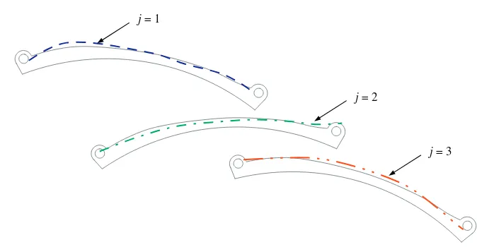
Zhao et al. [22]present applications in which the first and last points on each profile of similar length are fixed. The segmentation process for variable length profiles remains intact when fixed ends are required by merely introducing the additional constraint in Eq.(32). As an example,Fig. 11a shows three profiles with a fixed-end requirement. The arc lengths of the profiles areC1= 12.24,C2= 12.90, andC3= 14.13. A desired piece length ofsd= 0.35 was specified, producingm1∗= 75,
m2∗= 89, andm3∗= 98. A design vector with six segments was selected,V¼ C M M C M C½ , and a minimum number of pieces per segment ofα= 8 was designated. The final shape-approximating rigid-body chain is shown inFig. 11b, which exhibits a
profile matching error ofEmax= 0.18. Note that this rigid-body chain with fixed ends exhibits 7 DOF. A mechanization process must still be conducted to reduce the DOF to a suitable number of actuators.
8.2. Automotive driver's seat
To illustrate the complete shape-change synthesis process, consider an automotive seat that should comfortably conform to the full range of driver sizes. According to Frey and Tecklin[40], about 80% of American adults suffer from pain in the lumbar spine during their lifetime. Musculoskeletal disorders can be caused by long periods of driving, the use of manual or stick shift transmissions, and the lack of adequate car seat adjustment[41]. Substantial research in human factors of seat or chair design can be found in the literature[42]. Extensive human measurements at different ages can be found in[43]. These studies can be utilized to define an automotive seat profile that can be adjusted to satisfy the seating requirements for most drivers.
j = 1
j = 2
j = 3
a
b
Fig. 11.(a) Fixed-end profiles. (b) The final, rigid-body, shape-approximating chain havingEmax= 0.18.
In the design of a seat profile,Fig. 12a shows three drivers seated relative to the steering wheel. The first profile (j= 1) conforms to a female from the 1stpercentile group. The second profile (j= 2) refers to the 99th percentile male group. A
mid-range profile is inserted to ensure that a middle profile is achieved corresponding to average-sized drivers and to produce a smooth transition between the two extreme driver sizes. Accordingly, an intermediate profile (j= 3) is created from the 50th
percentile male group. The three design profiles shown inFig. 12b are identified with significantly different lengths of both the seat and the back rest portions. These profiles have arc lengths ofC1= 44.42,C2= 51.98 andC3= 54.39. A desired piece length is set assd= 0.35, generating target profiles havingm1∗= 127,m2∗= 149, andm3∗= 155 pieces.
A five-segment seat was specified for the segmentation process. A search through every possible five-segment design vector was performed, with V¼ C M M M C½ producing the lowest error approximation.Fig. 13presents the results from the segmentation process yielding Emax= 0.27. Further, two revolute joints exhibited minimal rotation. They were eliminated, creating a compound segment within the chain as shown inFig. 13b, yieldingEmax= 0.50. Using the mechanization methods described inSection 6, links were added to reduce the DOF and form a mechanism that is able to alter its shape between the three profiles in Fig. 14. Incorporating prismatic joints between the segments and the frame,Fig. 14shows the final single-DOF mechanism that moves between the three profiles to suit the small, average, and large drivers. The mechanism can be effectively actuated via any one of the five prismatic joints.
9. Conclusion
A planar serial chain of rigid bodies connected by revolute and prismatic joints can be reconfigured to approximate any number of curves. A necessary step in the design of rigid-body shape-changing mechanisms is to determine the planar chain that best matches a set of curves, called design profiles. This paper presents the theory and a practical methodology for defining the shapes of the rigid bodies and identifying the proper sequence of revolute and prismatic joints to connect them in order to
99
thpercentile male
1
stpercentile
female
j = 1j = 2
j = 3
Fig. 12.(a) The silhouettes of a small, an average and a large driver[43]. (b) Seat design profiles that suit the small, average and large drivers from (a).
1
5
4
3
2
Segments
are merged
Headrest
1
3
2
a)
Optimized design with Emax = 0.2736b)
Optimized design with reduced number of segments, Emax = 0.4988Fig. 13.The three seat profiles can be approximated by the five segment shape-approximating chain in (a). The creation of a compound segment reduces the chain to three segments in (b) with only a modest increase in error.
minimize the error between the chain and the design profiles. In service of this process, the design profiles are converted to target profiles, curves by which neighboring points are approximately the same distance apart. Contiguous sets of points may be compared among target profiles to identify both the ideal geometry for the rigid bodies comprising the chain as well as the joint locations and types. Several examples display the utility of the described procedures.
Acknowledgment
This material is based upon work supported by the National Science Foundation under Grant #1234374 and #1234383. Additionally, the first author would like to thank the Ministry of Higher Education of Malaysia for sponsoring his studies and research at the University of Dayton.
References
[1] A.Y.N. Sofla, S.A. Meguid, K.T. Tan, W.K. Yeo, Shape morphing of aircraft wing: status and challenges, Mater. Des. 31 (3) (2010) 1284–1292. [2] S. Vasista, L. Tong, K.C. Wong, Realization of morphing wings: a multidisciplinary challenge, J. Aircr. 49 (1) (2012) 11–28.
[3] G.J. Frank, J.J. Joo, B.P. Sanders, D.M. Garner, A.P. Murray, Mechanization of a high aspect ratio wing for aerodynamic control, J. Intell. Mater. Syst. Struct. 19 (9) (2008) 1101–1112.
[4] D. Inoyama, B.P. Sanders, J.J. Joo, Topology optimization approach for the determination of the multiple-configuration morphing wing structure, J. Aircr. 45 (6) (2008) 1853–1862.
[5] S. Kota, J. Hetrick, R. Osborn, Design and application of compliant mechanisms for morphing aircraft structures, Proc. of the SPIE 5054, Smart Structures and Materials Conference, San Diego, CA, USA, 2003, pp. 24–33.
[6] J.D. Anderson, Fundamentals of Aerodynamics, McGraw-Hill, New York, 2012.
[7] J.T. Wong, Shape Morphing Structures via Intercalation Compounds. (M.Eng. Thesis) Massachusetts Institute of Technology, 2007. [8] G.N. Washington, Smart aperture antennas, Smart Mater. Struct. 5 (6) (1996) 801–805.
[9] J.W. Martin, J.A. Main, G.C. Nelson, Shape control of deployable membrane mirrors, Proc. of the ASME Adaptive Structures and Materials Systems Conference, Anaheim, CA, USA, 1998, pp. 217–223.
[10] U. Heselhaus, W. Richter, Folding roof for a convertible, U.S. Patent Number 6,270,143 B1, 2001.
[11] A.G. Erdman, G.N. Sandor, S. Kota, 4th ed., Mechanism Design: Analysis and Synthesis, vol. 1, Prentice-Hall, New York, 2001. [12] S. Hirose, Y. Umetani, The development of soft gripper for the versatile robot hand, Mech. Mach. Theory 13 (3) (1978) 351–359. [13] M. Kato, S. Sano, Y. Hiyoski, Variable section extrusion die set and variable extrusion molding method, U.S. Patent Number 3,526,020, 1996. [14] M.D. Murphy, A. Midha, L.L. Howell, The topological synthesis of compliant mechanisms, Mech. Mach. Theory 31 (2) (1996) 185–199. [15] K.J. Lu, S. Kota, Design of compliant mechanisms for morphing structural shapes, J. Intell. Mater. Syst. Struct. 14 (3) (2003) 379–391. [16] Y.M. Moon, Bio-mimetic design of finger mechanism with contact aided compliant mechanism, Mech. Mach. Theory 42 (5) (2007) 600–611.
[17] M.N. Mohd Zubir, B. Shirinzadeh, Y. Tian, A new design of piezoelectric driven compliant-based microgripper for micromanipulation, Mech. Mach. Theory 44 (12) (2009) 2248–2264.
[18] P. Limaye, G. Ramu, S. Pamulapati, G.K. Anathasuresh, A compliant mechanism kit with flexible beams and connectors along with analysis and optimal synthesis procedures, Mech. Mach. Theory 49 (3) (2012) 21–39.
[19] P.R. Lawson, J.L. Yen, A piecewise deformable subreflector for compensation of Cassegrain main reflector errors, IEEE Trans. Antennas Propag. 36 (10) (1988) 1343–1350.
[20] A.P. Murray, J.P. Schmiedeler, B.M. Korte, Kinematic synthesis of planar, shape-changing rigid-body mechanisms, J. Mech. Des. 130 (3)
(2008)(032302-1-10).
[21] J.A. Persinger, J.P. Schmiedeler, A.P. Murray, Synthesis of planar-rigid-body mechanisms approximating shape changes defined by closed curves, J. Mech. Des. 131 (7) (2009)(071006-1-7).
[22] K. Zhao, J.P. Schmiedeler, A.P. Murray, Design of planar, shape-changing, rigid-body mechanisms for morphing aircraft wings, J. Mech. Robot. 4 (4) (2012)(041007-1-10).
[23] W.A. Khan, J. Angeles, A novel paradigm for the qualitative synthesis of simple kinematic chaines based on complexity measures, J. Mech. Robot. 3 (3) (2011)(031010-1-11).
[24] T. Huang, H.T. Liu, D.G. Chetwynd, Generalized Jacobian analysis of lower mobility manipulators, Mech. Mach. Theory 46 (6) (2011) 831–844.
[25] H. Ding, F. Hou, A. Kecskeméthy, Z. Huang, Synthesis of the whole family of planar 1-DOF kinematic chains and creation of their atlas database, Mech. Mach. Theory 47 (1) (2012) 1–15.
[26] J.A. Horst, I. Beichl, Efficient piecewise linear approximation of space curves using chord and arc length, Proc. of the SME Applied Machine Vision Conference, Cincinnati, OH, USA, vol. 2, 1996, pp. 744–747.
[27] F. Mokhtarian, A.K. Mackworth, Theory of multi-scale, curvature-based shape representation for planar curves, IEEE Trans. Pattern Anal. Mach. Intell. 14 (8) (1993) 789–805.
[28] K.S. Arun, T.S. Huang, S.D. Blostein, Least-squares fitting of two 3-D point sets, IEEE Trans. Pattern Anal. Mach. Intell. 9 (5) (1987) 698–700.
Fig. 14.The results of the mechanization process: (a) The seat is adjusted for a 1stpercentile female. (b) The seat accommodating a 50thpercentile male. (c) The car seat is positioned for a 99thpercentile male.
[29] S. Umeyama, Least-squares estimation of transformation parameter between two point patterns, IEEE Trans. Pattern Anal. Mach. Intell. 13 (4) (1991) 376–380.
[30] B.K.P. Horn, Closed-form solution of absolute orientation using unit quaternions, J. Opt. Soc. Am. 4 (4) (1987) 629–642. [31] B. Zitová, J. Flusser, Image registration methods: a survey, Image Vis. Comput. 21 (11) (2003) 977–1000.
[32] H.G. Burchard, Discrete curves and curvature constraints, in: P.J. Laurent, et al., (Eds.), Curves and Surfaces in Geometric Design, A. K. Peters Ltd., Natick, MA, 1994, pp. 67–74.
[33] S. Stahl, Introduction to Topology and Geometry, John Wiley, Hoboken, NJ, 2005.
[34] D.G. Zill, M.R. Cullen, Advanced Engineering Mathematics, Jones & Bartlett Publishers, Sudbury, MA, 2006. [35] M.J. McCarthy, J.S. Goh, Geometric Design of Linkages. 2/e Springer-Verlag, New York, 2011.
[36] S.S. Balli, S. Chand, Defects in link mechanisms and solution rectification, Mech. Mach. Theory 37 (9) (2002) 851–876.
[37] E.C. Kinzel, J.P. Schmiedeler, G.R. Pennock, Kinematic synthesis for finitely separated positions using geometric constraint programming, J. Mech. Des. 128 (5) (2006) 1070–1079.
[38] J. Yao, J. Angeles, Computation of all optimum dyads in the approximate synthesis of planar linkages for rigid-body guidance, Mech. Mach. Theory 35 (8) (2000) 1065–1078.
[39] D.A. Perkins, A.P. Murray, Singularity free revolute–prismatic–revolute and spherical–prismatic–spherical chains for articulating planar and spherical single degree of freedom mechanisms, J. Mech. Robot. 4 (1) (2012)(011007-1-6).
[40] J.K. Frey, J.S. Tecklin, Comparison of lumbar curves when sitting on the Westnofa Balans® multi-chair, sitting on a conventional chair, and standing, Phys. Ther. 66 (1986) 1365–1369.
[41] P.T. McCabe, Contemporary Ergonomics 2004, CRC Press, Boca Raton, FL, 2004.
[42] S. Pheasant, Bodyspace: Anthropometry, Ergonomics, and the Design of Work, 2nd ed. Taylor & Francis, London, UK, 1996. [43] A.R. Tilley, The Measure of Man and Woman, Revised ed. John Wiley & Sons, New York, NY, 2002.