PROJECT COMPLETION REPORT
FOR
SHORT TERM RESEARCH GRANT
DESIGN OPTIMIZATION AND UP-SCALING OF FIRE FIGHTING MACHINE:
WATER SPRAYING AND TRACK MECHANISM SYSTEM APPROACH
Principal Researcher
: Ir. Dr. Tan Chee Fai
Co-Researcher
: Shafizal bin Mat
Project Code No
: PJP/2011/FKM (29a)/S00988
Report Submission Date : 18 June 2013
Department of Design & Innovation
ABSTRACT
DESIGN OPTIMIZATION AND UP-SCALING OF FIRE FIGHTING MACHINE:
WATER SPRAYING AND TRACK MECHANISM SYSTEM APPROACH
(Keywords: optimization, fire fighting, water spraying, control system)
Fire fighting is risky profession. They are not only extinguishing fires in tall buildings but also
must drag heavy hoses, climb high ladders and carry people from buildings and other situations.
There are many fire fighters lost their lives in the line of duty each year throughout the world.
The statistics of the fire fighter fatalities are still maintain at high level every year and it may
continue to increase if there is no improvement in fire fighting techniques and technology. The
report describes the findings on water pressure loss analysis and track mechanism system of fire
fighting mobile robot prototype.
Key Researchers:
Ir. Dr. Tan Chee Fai
Shafizal bin Mat
E-mail: [email protected]
Tel. No.: 06 234 6710
ACKNOWLEDGEMENT
The project is funded by Universiti Teknikal Malaysia Melaka under University Short Term Research
Grant Scheme (project number: PJP/2011/FKM(29a)/S00988). The author gratefully acknowledges the
support of the Centre of Research and Innovation Management (CRIM) and Faculty of Mechanical
TABLE OF CONTENTS
1.0
INTRODUCTION...1
2.0
CURRENT FIRE FIGHTING MOBILE ROBOT...1
3.0
DESIGN ANALYSIS WATER SPRAYING SYSTEM...9
3.1
Pressure Loss Analysis...9
3.2
Results...13
4.0
CONCEPTUAL DESIGN OF TRACK SYSTEM...14
4.1
Concept Selection...15
4.2
Optimization Using MSC ADAMS...16
5.0
CONCLUSION...17
REFERENCES...17
1.0 INTRODUCTION
Fire fighter need to work in a long and irregular hours and unfriendly working environment such as high temperature, dusty and low humidity, firefighters are also facing with potentially life threatening situation such as explosion, collapsed building and radioactive. The common equipment used by firefighters such as flat head axe, halligan bar, turnout jacket, fire retardant or bunker pants, boots, flashlight, helmet, face mask, and gloves do not significantly reduce risk on their lives when facing those life threatening situations.
In the USA, the traumatic death rate amongst firefighters shows that 1.9 firefighters are killed per year, per 100,000 structure fires which is the rate only slightly lower than that obtained in the early 1980s (IAFF, 2000). However, this rate was increasing to 3.0 per 100,000 structure fires across a thirty year period which is peaking in the 1990s (Kyle, 2007). There are many causes for Line of Duty Deaths (LODD) such as smoke inhalation, burns, crushing injuries and related trauma (Rosmuller and Ale, 2008). As a result of this, over the past few years, research and development on firefighting technology is extensively made around the world especially in US, Japan, and a number of European companies. There were many studies (SQFE, 2007; Sofge, 2007; Konda, 2008; HKFSD, 2008; NEVA, 2008) had emphasized on machine development to replace fire fighter to fight fire in dangerous situations and to reduce the fire fighter risk. The machines help the fire fighter using extinguishing agent such as water, foam or others without fire fighter having to set up or operate directly in danger areas.
Amano (2000) highlighted the weaknesses of existing machine design and suggest integration of all important elements in developing fire fighting machine so that a successful rescuing process can be achieved. These elements are size, weight, cost and performance. Therefore, this research was integrated required technical aspects to develop a mobile machine based on the end user requirements which is fire fighting rescue team. The paper describes the water pressure loss analysis of the developed fire fighting mobile robot.
2.0 CURRENT FIRE FIGHTING MOBILE ROBOT
The rapid development in technology nowadays, directly improve the tools and equipment used in fire fighting. With these advance tools and equipment, fire fighting can be more effective and efficient. Besides, it also reduces the risk to minimum level. Moreover, the damages of fire incident can be reduced. Fire fighting mobile robot is one of the solution that able to reduce the fire hazards risk on fire fighter. Different type of current available fire fighting machine will be described.
LUF60:
tunnels, aircraft hangers, parking garages, chemical plant, etc. There are some significant features of this machine. The monitor nozzle has a flow rate up to 800 GPM and it can blow the water beam as far as 80m. In order to enhance it mobility in high temperature condition, it is equipped with rubber track system which is rated to 400 degrees Fahrenheit. The rubber track system enables the robot tWo climb the stair. Besides, this machine able to operate on slopes of maximum 20 degrees with the ventilation tube at a maximum 45 degree angle (NRT, 2013).
Figure 1: LUF60
(Photo reprinted from NRT, 2013)
FIREROB:
FIREROB (Figure 2) is a remote controlled mobile robot that is used to fight fires, search and inspect fire scene. The FIREROB is protected from heat with a heat shield. It is equipped with high-pressure water mist extinguishers to control the fires. Besides, it also equipped with thermal imaging cameras and sensors for observation and monitoring purpose in fire scene. Two operation options for the FIREROB are available, which are with heat shield and without heat shield.
FFR-1:
FFR-1 (Figure 3) is a fire fighting robot that used to enable firefighters to carry out difficult missions. The FFR-1 is a remote controlled double-tracked robot that carry monitor and used to extinguish fire. The robot is designed to operate under hazardous environment conditions as high temperatures, poisonous materials and inside unsafe buildings.
Figure 3: FFR-1 Fire Fighting and Rescue Wireless Robot (bowen39, 2012)
Operating FFR-1 enables firefighters to execute missions in confined spaces, narrow streets, industrial buildings, stores, tunnels, airports, military installations, power plants, chemical plants and others. FFR-1 is easily transported on a modified vehicle or a trailer, imparting an operational advantage for firefighters at early stage of the fire as well as during the whole operation. The FFR-1 has a internal double-walled cooling system to avoid the overheating cause by high external temperature. FFR-1 is a highly maneuverable robot with cross-country capabilities. It runs on treads and can climb up to 30 degree incline dragging a 3 inch fire hose (Mgsemi, 2005).
FIREMOTE 4800:
Figure 4: Firemote 4800
(Photo reprinted from Ryland Research Limited Company, 2011)
MVF-5:
The MVF-5 as shown in Figure 5 is a multifunctional robotic fire fighting machine manufactured by Croatian manufacturer DOK-ING, to put out fires in unreachable areas and life threatening conditions. It is a fire fighting vehicle that operated by a single operator and controlled by using remote control. With the remote-control technology GPS-INS (Global Position System- Inertial Navigation System), the system is able to be controlled in the range of 1500m.
Figure 5: MVF-5 Autonomous Fire Fighting Machine (Photo reprinted from DOK-ING Company, 2010)
designed 3-level hydraulic arm has 360° rotation. This enables high pressure cannon delivering of the extinguishing liquids in all desired directions (DOK-ING Company, 2010).
JMX-LT50:
JMX-LT50 (Figure 6) is equipped with barrier ability, the long-distance remote control, and the formidable spray water class. This robot is made up of the remote-controller, chassis, liquid-control fire monitor and control system. The robot is utilizing the water supplied from rear coupling and it is able to protect itself by automatic mist spraying. The remote control water cannon of the robot is able to spray the water in different angle and distance. The mobility of JMX-LT50 is using the wheel-tire moving structure. This design made this robot move in the different terrain and overcome different kind of obstacle (Chinawe, 2013).
Figure 6: JMX LT50 (Photo reprinted from Chinawe, 2013)
SACI 2.0:
Figure 7: SACI 2.0 (Photo reprinted from ARMTEC, 2013)
This machine can pump fluids for three solid hours before needing a recharge. Other than that, it can operate with a full load capacity up to a minimum of six hours. For convenience, this machine has its charging system mounted in its transport car. It has lighting system to light up the dark environment when on duty. SACI firefighting robot was designed and built with modular approach. Besides, SACI is equipped with a trapezoidal track that is capable to cross different obstacles.
ArchiBot-M:
The Korean designed firefighting robot, namely, ArchiBot-M (Figure 8) is the mobile robot that used in the human inaccessible location. It is used for on-site checking and clears the path for fire fighter. The robot was equipped with an special designed independent suspension system for stair climbing and working in high temperature. The robot also is designed with waterproof ability and equipped with a cooling system in order the robot to be worked in the hot environment.
Thermite T2
The Thermite robot (Figure 9) is developed to be handled different hazardous environment such as forest fire and chemical fires. The robot equipped with remote capabilities to ensure the robot is able to control with stand-off distance and a multi-directional monitor to ensure the safety of the user. The remote control distance is around 400 m. The Thermite is designed for rough terrain as well as building environment. The robot has short start up time that is enable the robot has shorter respond time.
Figure 9: Thermite T2 (Photo reprinted from Howeandhowe, 2013)
FIGOV
Figure 10: Side View of FIGOV
Figure 11: FIGOV
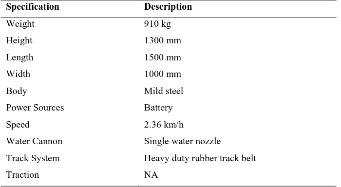
Table 1: General specifications of the FIGOV
Specification Description
Weight 910 kg
Height 1300 mm
Length 1500 mm
Width 1000 mm
Body Mild steel
Power Sources Battery
Speed 2.36 km/h
Water Cannon Single water nozzle
Track System Heavy duty rubber track belt
3.0 DESIGN ANALYSIS WATER SPRAYING SYSTEM
The engineering design analysis is conducted on the structure of the FIGOV in order to ensure its reliability to withstand the load experienced during operation. As water is projected from a nozzle to form a ‘jet’ or fire fighting stream, the nozzle tends to recoil in the opposite direction. Therefore, it is essential to counter the hose nozzle
reactive force generated during fire fighting process. Manual calculation and computer aided engineering software utilizing Finite element analysis is applied in the study. Analysis made consider the maximum load applied on the machine and the maximum water pressure experienced by the machine during operation. Calculation made is to check the stability of the machine when the machine is in use.
Computer Aided Engineering (CAE) and design optimization is becoming more crucial in modern engineering design. It is because it applies numerical techniques to engineering systems in order to assist the engineering designers. This approach will be useful in improving the system's performance, weight, reliability, and/or cost.
CAE analysis and optimization methodologies can be applied during the product development stage to ensure that the finished design will have the high performance, high reliability, low weight, and/or low cost. Alternatively, design optimization methods can also be applied to existing products to identify potential design improvements. After completing design analysis, the prototype fabrication of the FFM proceeded. The prototype produced is a full scale prototype.
3.1 Pressure Loss Analysis
Pressure Loss through Hose and Height
Figure 12: Pressure loss due to hose length and height
Bernoulli Principle which relates pressure, velocity and elevation between two points in flow field is applied. Assumption made using the principle is the flow is steady, incompressible, irrotational and nonviscous. The following formula is used in Fire and Rescue Department.
EP = NP + FLHose + FLAppliance + PElevation (1)
Where,
EP = Engine Pressure NP = Nozzle Pressure
FLHose = Friction Loss in the fire hose
FLAppliance = Friction Loss in the appliance
PElevation = Pressure loss or gain due to elevation
Friction loss in the hose, FLHose is given by a Friction Loss Equation as below [18]
FLHose = CQ2L (2)
Where,
FL = friction loss (expressed in psi) C = coefficient of friction
Q = flow rate in hundreds of gallons (gpm/100) L = Length of hose in hundreds of feet (L/100)
Based on Bernoulli’s equation, it is given that:
FL V gz P V gz
P1+ 1 + 12 = 2 + 2 + 22 + 2 1 2 1 ρ ρ ρ
ρ (3)
Where,
P
= Pressureρ
= Fluid densityg
= Gravityz
= HeightV
= Fluid velocityf
h
= Friction lossesWhereas based on Continuity equation, it is known that:
2 2 1 1
V
A
V
A
Q
=
=
(4)Where,
Q
= Volume flow rateNozzle Force
In analyzing force at nozzle of FFM, the system can be considered as a thermodynamic system that has an open system or control volume and involves the flow of fluid through the fix volume. As fluid moves through the control volume, the mass entering the control volume is equal to the mass leaving the control volume. The surface enclosing the control volume is referred to as the control surface. The force at nozzle is determined with information such as, maximum water pressure and nozzle dimension using Bernoulli’s equation and momentum equation. The component involve in the force determination of the nozzle as shown in Figure 5.
Figure 13: Cross sectional view of water nozzle
The water inlet and outlet velocity
V
1 andV
2 can be obtained by solving Continuity Equation.1
V
1
A
Q
=
21
4
D
Q
π
=
(5)
Based on the Friction Loss, the Nozzle Pressure can be calculated based on the following formula. (Referring to NFPA 1002 Standard of Fire Apparatus Driver/Operator Profesional Qualifications)
3.2 Results
Pressure Loss through Hose and Height
Flow rate, Q2 = V2A2 = 629.257 gpm
Therefore, Friction Loss is
FL = 0.00065V22 = 1.399 kPa
Based on the Friction Loss, the Nozzle Pressure can be calculated based on the following formula.
NP = 11.64 bar
Nozzle Force
For, D1=0.0635m, D2 = 0.03302m,
Q
=1 3
0397
.
0
m
s
− , the water inlet and outlet velocity V1 and V2 obtained bysolving Continuity Equation.
1
V
1 A Q = 2 1 4 D Qπ
=
=
12
.
53
ms
−12
V
2 A Q = 2 2 4 D Qπ
=
=
46
.
36
ms
−1Based on the Friction Loss, the Nozzle Pressure can be calculated based on the following formula.
NP = EP - FLHose - FLAppliance + PElevation = 11.64 bar
Bernoulli’s Momentum equation is used to determine the force,
F
nozzle, required to hold the nozzle in it position.(
V
2V
1)
P
1A
1P
2A
2Q
F
nozzle=
ρ
−
−
+
=−2,257N4.0 CONCEPTUAL DESIGN OF TRACK SYSTEM
Figure 14 is the first conceptual design of the fire fighting machine. This concept is to produce a light weight track system which needs a lower power to move it compared to the current fire fighting machine track system. It uses a timing belt type as its track. By using timing belt, it can operate over a very wide range of speeds. Besides that, no lubricant is needed. A timing belt also does not stretch appreciably or slip and consequently transmits power at a constant angular ratio. The design of the track at both ends is inclined shape. This enables the track to move easily on rocky terrain. It is also able to run smoothly as it can run over the large rock easily with such design comparing to the more flat type. For its chassis, it is only use a simple bar type where only a simple bar is holding the sprockets, suspensions and roller while it is connected to the fire fighting machine body. This can save a lot of material (cost) since it does not have complicated structure. Furthermore, it will become lighter when the structure of the track system is simplified. The suspension system used in this concept is the motorcycle type absorber. It is because it is easy to find in the market and it is easy to be installed.
Figure 14: Conceptual design 1
Figure 15: Conceptual design 2
The third conceptual design of track system in Figure 16 uses roller chain as its track. Roller chain is used because there is no slippage or creep is involved. Hence, there is no power lost due to slippage. Besides that, it has the ability to drive a number of shafts from a single source of power. Moreover, roller chain seldom failed because they lack of tensile strength. Chain drives are also more practical at slow speeds, yet will operate efficiently at high temperatures. Furthermore, chains are generally easier to install than belts. On the others hand, they are not subject to deterioration by oil, grease, or sunlight, and generally withstand chemical and abrasive conditions. Chains can also operate in wet conditions while stretch under normal operating conditions is slow, and chains require less take-up adjustment than do belts Chains are suitable for use on reversing drives too. Some soft materials are attached to the roller chain in order to make it quiet when it is rolling on the ground. For the chassis, rigid frame type is used as it is suitable to withstand high moment, stress and force. It also can hold the components of the track system tightly. Besides that, it is also a good choice as it not easy spoiled due to the vibration and shock since it is rigid. For the suspension, it is same as first conceptual design where it uses motorcycle shock absorber.
Figure 16: Conceptual design 3
4.1 Concept Selection
Table 2: Weight decision method
There are three conceptual design evaluated in the Weight Decision Matrix. Firstly, the design criteria are identified by which the concepts will be evaluated. The design criteria are identified as (1) material cost, (2) manufacturing cost (3) reparability, (4) durability, (5) reliability, (6) time to produce and (7) efficiency. Next, each of the design criteria is given weighting factor. It is done in the objective tree. The weighting factor will be used in the Weight Decision Matrix in the Table 2. The score in the table 3 is derived according to 11-point scale.
The rating for each concept at each design criterion is obtained by multiplying the score by the weighting factor. Thus, for the criterion of material cost in the first conceptual design, the rating is 0.12 x 8 = 0.96. The overall rating for each concept is the sum of these ratings.
After total all the rating, the conceptual design 3 has the highest ranking followed by conceptual design 1 and lastly is the conceptual design 2. Their rating is 7.32, 7.04 and 7.00 respectively. Therefore, conceptual design 3 is selected as the new design for fire fighting machine.
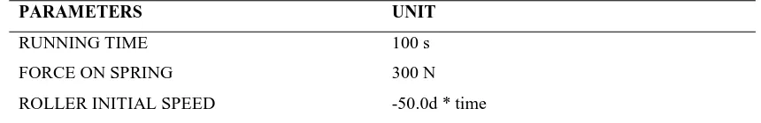
4.2 Optimization Using MSC ADAMS
Figure 17: Optimization of the position of the roller holder and absorber in the track system using MSC ADAMS Table 3: Parameter used in MSC ADAMS for optimization
PARAMETERS UNIT
RUNNING TIME 100 s
FORCE ON SPRING 300 N
ROLLER INITIAL SPEED -50.0d * time
5.0 CONCLUSION
In this paper, the pressure loss of nozzle and nozzle force has been analyzed. Three fundamental hydraulic principles were used to analyze the nozzle, namely, Bernoulli’s Equation, Darcy-Weibach Equation and Continuity Equation. Based on the calculation, total pressure loss of nozzle is 11.64 bar. For the nozzle force, the nozzle reaction force to hold the nozzle is 2257 N.
REFERENCES
Amano, H., 2000. Present Status and Problems of Fire Fighting Robots. SICE 2002. Proceedings of the 41st SICE Annual Conference, Vol. 2, pp:880- 885.
Americancrane. http://www.americancrane.com/Telerob/Firerob.htm. Accessed on 8 Mar 2013.
Armtec. http://v2.armtecbrasil.com/index.php?produto=2. Accessed on 8 Mar 2013.
Chinawe. http://www.chinawe.net/html/xf/thxf/20100609_268016.html. Accessed on 8 Mar 2013.
DOK-ING.Firefighting (MVF-5). http://www.dok-ing.us/products.html. Accessed on 5 October 2011.
Drbfatec. http://www.drbfatec.com/frd_center/fighting_m.htm. Accessed on 8 Mar 2013.
Hisanori, A., 2002. Present Status and Problems of Fire Fighting Robots. SICE 2002. Proceedings of the 41st SICE Annual Conference, Vol. 2, pp: 880- 885.
HKFSD. Mobile Fire Fighting Supporting Machine LUF 60R. http://www.hkfsd.gov.hk/home/images/ equipment/fire/e_luf60.html. Accessed on 13th September 2008.
Howe and Howe. http://www.howeandhowe.com/uploads/1/5/2/4/15246154/rs1-t2_quad_chart.pdf. Accessed on 8 Mar 2013.
International Association of Fire Fighters (IAFF), 2000. Death and Injury Survey, Washington. http://www.iaff.org/HS/PDF/2000%20D&I.pdf. Accessed on 5 September 2008.
Kyle, S.N., 2007. NFPA Releases Firefighter Death Study, U.S.A. http://cms.firehouse.com/content/section/news. Accessed on 5 September 2008.
Konda, A. “The Fire Fighting Snake Robot. Europe,” Available from: http://www.sintef.com. Accessed on 4th September 2008.
NEVA. Mobile Fire Fighting Robot. Russia.http://www.neva.ru/CNII-RTC/Firemen/html. Accessed on 13th September 2008.
Mgsemi. http://mgsemi.com/hewsales/ffr-1.html. Accessed on 8 Mar 2013.
NEVA, “Mobile Fire Fighting Robot. Russia,” Available from: http://www.neva.ru/CNII-RTC/Firemen/html. Accessed on 13th September 2008.
Rita, F., P.R.L, Fahy and J.L. Molis, 2011. Firefighter Fatalities in the United States-2010. National Fire Protection Association, Fire Analysis and Research Division.
Rosmuller, N. and Ale, B.J.M., “Classification of fatal firefighter accidents in the Netherlands: Time pressure and aim of the suppression activity,” Journal of Safety Science, No. 46, 2008, pp. 282 –290.
Ryland Research Limited. (2001) “Firemote 4,800” Bordon, (U.K.): Trade Brochure.
Shanghai Qiangshi Fire-fighting Equipment Co. Ltd., 2007, “Qiangshi Fire Fighting Robot, China,” Available from: www.qs119.com/en/ showpro.asp?id=530. Accessed on 5th September 2008.
Sofge, E., 2007. First Firefighting Robots Deployed, Could Spark Autonomous Dept. Las Vegas. http://www.popularmechanics.com/science/roboticsl. Accessed on 5 September 2008.
PUBLICATIONS
1. Tan, C.F., Ranjit. S.S.S., Kher, V.K. and Kong, H.F. 2013. Up-Scaling and Optimization of Fire Fighting
Ground Vehicle Track System. Applied Mechanics and Materials, 315:236-240.
2. Tan, C.F., Ranjit. S.S.S. and Anas, S.A. 2012. Water Pressure Loss Analysis of Mobile Machine for Fire