S. Thiruchitrambalam1,* S.Hemavathi2, Ahmad Rivai3 and Sunil Pandey4
1,3
Faculty of Mechanical Engineering, Universiti Teknikal Malaysia Melaka (UTeM), Melaka, Malaysia
2
School of Civil Engineering, Linton University College, Negeri Sembilan,Malaysia.
4
Department of Mechanical Engineering, Indian Institute of Technology Delhi (IITD), India.
*email: [email protected]
Abstract
For open root pass girth welds, manual welding with cellulosic electrodes is still the most widely used process in spite of its susceptibility to hydrogen-induced defects. Barring considerable losses due to production delays and failures, the pipeline industry has learnt to live with these defects, as cellulosic electrodes are capable of producing low cost, high penetration welds- a prerequisite for pipe welding. Nevertheless, attempts have been made by researchers to reduce hydrogen levels in pipeline weldments either by altering the procedure techniques or by adopting different processes or by introducing new fabrication materials and methods. The Plasma Enhanced Shielded Metal Arc Welding (PESMAW), a modified version of the conventional Shielded Metal Arc Welding (SMAW) is one among these attempts, aimed to amplify penetration levels in general-purpose, rutile-coated electrodes at comparatively lower currents. It employs gas carrying tubular covered electrodes with a specially designed Universal Electrode Holder (UEH), which has provisions for external gas supply through the orifice of the electrodes. The gas introduced at the tip of the electrode gets ionized in the arc column and develops auxiliary plasma. This enhances the heat content of the weldment and yields high penetration weld beads at low currents. This paper presents an investigation on the performance of PESMAW by applying it to the welding of mild steel sheet of thickness 5 mm. The effect of welding current on bead geometry & shape relationships of welds, micro hardness analysis and weld microstructure were studied. Flat position ‘bead on plate’ technique was used to deposit weld beads in a mechanized manner. CO2 was used as the orifice gas
through the general-purpose rutile coated tubular electrodes. It was observed that the flow of orifice gas during welding resulted in the increase in weld penetration, while the absence of plasma gas resulted in flatter and wider weld beads.
Keywords:Weld penetration, PESMAW, Tubular electrodes, SMAW
1 INTRODUCTION
Open root or stringer pass, one of the most critical pipe welds in the “field welding” of cross country pipelines, is also considered as one of the most difficult to make in terms of proper fusion and internal bead profile [1]. The speed at which the root pass of each pipe is made determines the production time of the entire stretch and is solely dependant on the type, and reliability of the adopted welding technique [2]. Thus far, three methods have been used extensively for root welding viz. Shielded metal arc welding (SMAW), Gas metal arc welding (GMAW) and Gas
tungsten arc welding (GTAW) each of which has its own advantages and disadvantages. The SMAW process, is highly versatile, has low equipment cost but requires high hydrogen cellulosic electrodes (primarily AWS EXX10-type), which are potentially susceptible to one of the most harmful weld defects, the cold or delayed or under bead cracks [3]. The GMAW process, commonly referred as “MIG”, where the welds are made vertical down and therefore is a much faster process, but heat input is difficult to control and hence 100% fusion may not always be possible. The GTAW process also known as “TIG” is capable of producing high quality, defect free welds with
A Comparison Study on Relationship Between
Welding Current and Penetration for Plasma
negligible hydrogen. However, a higher level of operator skill is required for this process. These welds are made in the “vertical up” position, not a preferred position for girth welds, where travel speed is slow, and heat input is high.
Despite advances made in mechanized welding technology and the development of new consumables for girth welds, manual welding with cellulosic electrodes is still a preferred and the most widely used process for pipelines. Cellulosic electrodes, in spite of its high hydrogen content generate a forceful arc, producing high penetration welds, a mandatory requirement for pipe welding. This makes the industry to cope with the kind of defects it potentially inherits from using cellulosic electrodes, not with standing the huge losses it incurs from production delays and sporadic fatal failures. However attempts have been made by researchers to develop alternative methods to reduce the hydrogen levels in girth welds.
The plasma enhanced shielded metal arc welding (PESMAW), a variant of shielded metal arc welding [4] is one among these attempts, aimed to amplify the penetration levels of general purpose rutile coated electrodes at comparatively lower currents so as to make it usable for making pipe welds. This paper discusses the working principle of PESMAW process and presents an investigation made on weldment characteristics such as penetration, bead height, bead width, and percentage dilution etc with respect to varying arc current. A comparison study was also made on weldment characteristics of welds made by conventional SMAW process.
2. BACK GROUND
2.1 Plasma Enhanced Shielded Metal Arc Welding (PESMAW)
The plasma enhanced Shielded metal Arc welding (PESMAW) is a method of welding, cutting, piercing and surfacing metals, with an electric arc and a stream of selective gases or gas mixtures (CO2, O2 Ar, He,
Ar+CO2 mixture). Equipment includes a specially
designed Universal Electrode Holder (UEH) which houses provisions for holding tubular covered electrodes and gas supply, an a.c. or d.c. welding machine, gas tank and regulating gauges. The PESMAW electrode is a ferrous metal tube covered with a low hydrogen coating. The function of the tubular electrode, which is consumed during operation, is to conduct current for the establishment and maintenance of the arc. The bore of the tube directs the auxiliary plasma gas to the metal being welded. Both current and gasses are fed to the electrode through the
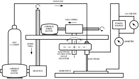
holder. The flow diagramof PESMAW process is shown in Fig. 1.
Fig. 1 Flow diagram for PESMAW process [5]
In PESMAW process, welding begins when an arc is struck between the tip of the electrode and the work. The high intensity arc melts the tip of the tubular covered electrode as well as the surface of the work below. Tiny globules of molten metal start flowing from the molten tip of the electrode due to the arc force. The orifice gas when introduced at the middle of the arc gets ionized instantaneously due to the high arc temperature. This ionized gas produces a number of effects. First, it increases the heat input rate of the arc and hence the arc energy by increasing the weld pool temperature. Second, the gas broadens the arc, makes the heat input distribution broader. This will change the surface tension gradients on the weld pool and thereby alter fluid flow. Finally, the centreline velocity of the orifice gas accelerates the flow of molten metal globules that increases the strength of the plasma jet thereby depress the centre of the weld pool further which results in deeper penetration.
2.2 Bead Geometry & Penetration
size, frequency of transfer, arc force, burn off rate and equilibrium in arc welding processes.
Fig. 2 Bead Geometry of a weldment
It has been established that the cooling rate of a weld can be predicted mainly from the weld bead geometry and the arc-travel rate. The optimal bead geometry is based on bead height (crown height), bead width and penetration that affect the total shrinkage, which in turn determine the residual stresses and thus the distortion. The weld penetration is greatly influenced by welding current, arc voltage, welding speed and welding angle. The depth of penetration increases with an increase in current, but decreases with an increase in voltage, increases with increase in arc-travel rate and decreases until the weld speed attains a minimum value, which depends on the arc-power. The other factors that influence the penetration are heat conductivity of the material (k), length and arc-force. The higher the heat conductivity of a material the lower is the penetration. Longer arc-lengths produce shallower penetration because of the lesser concentration of heat.
2 EXPERIMENTALINVESTIGATIONS
3.1 Materials
The weldment characteristics were investigated by depositing beads on mild steel plates with a dimension of 6.0x50.0x150.0 mm. The chemical composition of the base metal is given in Table.1.
Table.1 Chemical composition of base metal
C Si Cr Mn S P
0.179 0.124 0.042 0.404 0.024 0.0303
Cu Zr Ti Nb Co Ni
0.155 0.01 0.011 0.010 0.001 0.005
The surface of the samples was cleaned using 600 grit abrasive before surface melting. A general purpose, rutile coated (High Titania Potassium coating, AWS E 6013) mild steel tubular electrodes with an internal diameter of 1.2 mm and 450.0 mm length was used for the experiments.
3.2 Experimental apparatus and procedure
The consumable-coated electrode was clamped to the specially designed universal electrode holder (UEH), was set at 60o angle to the work piece by fastened it to an insulated block.
The block, in turn was attached to a lead screw whose angular velocity could be varied by a stepper motor, thus provided the means for altering the arc travel rate of the electrode. This stepper motor unit was placed over a carrier plate, which moves vertically up and down, was attached to a lead screw and was driven by a variable speed motor for altering the down feed in order to make the desired arc length. Output lines from an inverter power source were connected to the table and electrode respectively. Fig. 3 is a schematic representation of the set up.
Fig. 3 Schematic diagram of test circuit and relative motions of components
Since the unit design precluded “striking” an arc as is done manually, another method was devised to ignite the arc. After positioning the test piece on the carriage plate, the electrode was set at a sizable distance above its surface. The power source, carriage and electrode motions were then started simultaneously. When the electrode reached the optimum distance for arc initiation, a sharp edged copper coated graphite rod was inserted manually to ignite the arc. Once the electrode down feed was adjusted to provide a reasonably constant arc length, the welding operation was continued.
3.3 Weld preparation
The electrodes were baked for two hours at 120°C in an oven with temperature control within ±1 °C. The beads were deposited on cold base plates using pure CO2 as plasma gas flowing through the electrode
orifice. After depositing about 150 mm length of bead, the sample plate was kept in the open atmosphere and the process was repeated. No post-weld heat treatment was given to the weldments. The welding conditions used in the experimental procedure are shown in Table.2.
These conditions were chosen based on trial and error basis in accordance with current ranges suggested for the external diameter of the standard solid stick electrode core wire. All experiments were carried out with welding currents varied from 80 – 120 A, DCEN (straight polarity) and in flat position using a 6.3-kVA constant current inverter power source. The electrode feed rate and the welding speed were kept constant throughout the study.
Table.2 Experimental conditions and results Welding Current (I), A; Feed rate (F), mm/min; Arc
travel rate (S), mm/min; Arc Voltage (V), V; Penetration (P), mm; % Dilution (D) and Heat Input
(Q), J/mm
A Metallographic study and a micro hardness survey were carried out on the cross section of each specimen. The Metallographic study was conducted using light microscopy on the top bead, the grain coarsened and the grain-refined regions of the weld metal. Each bead was sectioned transversely at two points––one near the start (leaving about 50 mm from the start) and the
other near the end (leaving about 50 mm from the crater). These were metallurgically polished and then etched by 2% nital solution. The etched samples were scanned for measuring weld bead geometry and calculating percentage dilution.
3 ANALYSIS AND DISCUSSION
4.1 Bead geometry & penetration
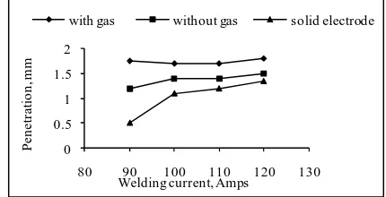
The depth of weld penetration or fusion is the distance below the original top surface of the work to the weld fusion line [9]. The essentiality of appropriate penetration has been investigated on many arc-welding methods and was fully demonstrated by many researchers [10]-[12]. The significance of PESMAW process is better recognized from Fig. 4 which shows the penetration level at different current range having the same electrode feed rates (F) and the same arc-travel speed (S) from the beads of weldment, made by both the conventional SMAW and the PESMAW
with gas without gas solid electrode
Fig. 4 Comparison of weld penetration as a function of current
It was clearly observed that the weld penetration increased invariably with an increase in current in both the conventional SMAW and the PESMAW processes. However, it was seen that the PESMAW process with CO2 gas fed tubular electrodes brought out the highest
penetration while the tubular electrodes without gas supply had the medium penetration and their counter parts (solid electrodes) in the conventional process gave the lowest penetration throughout the entire current range used in this study.
The higher penetration levels observed in CO2 gas fed
current of 90 A the conventional SMAW process yielded a comparatively modest penetration while the PESMAW process generated much higher depth of than the one produced by the former. The penetration acquired from the new process was uniform, highly symmetric and deeper at the specified conditions.
4.2 Percentage dilution
Percentage dilution [13] is defined as the ratio between the cross sectional area of penetration (Ap) to
the total area (At) of the bead.
0 0.2 0.4 0.6 0.8
80 90 100 110 120 130
P
e
rc
e
n
ta
ge
D
il
u
ti
o
n
Current, Amps
with gas without gas solid electrode
Fig. 5 Comparison of percentage dilution as a function of current
From Fig. 5 it was found that the beads made by PESMAW process have higher percentage dilution than that of those made by SMAW process at similar welding conditions. This increase is due to comparatively larger penetration area made by the new process as compared with the smaller one made by the conventional process.
4.3 Effect of heat input
The weldment characteristics are also dependent on the heat input, which determines the concentration of heat affecting the bead geometry, the penetration and the heat-affected zone (HAZ). During welding the variations occurred in the metallurgical structure of the fusion and heat-affected zones greatly affect the mechanical properties of the weldment. Properties such as toughness, fatigue strength, creep strength, corrosive resistance, plasticity, etc., of the weld metal are affected by the weld contour, the area of the HAZ, and the heat input. The heat input per unit length was calculated as given below:
φ
η
cosS VI
H = × (1)
It was noted from the Fig.6 there was a noticeable increase in heat input in PESMAW as compared with the conventional process at the same current level and welding speed.
Fig. 6 Comparison of heat input as a function of current
The amount of heat input to the weld metal increases with increase in voltage and decreases with increase in welding speed. Therefore the change in arc voltage is the reason for this elevation in the heat input. The change in arc voltage could be due to the presence of gas at the tip of the electrode, which accounts for the following reasons. a) During welding CO2 increases
the ionisation potential in the arc, which results in increase in voltage and b) CO2 when supplied at
ambient temperatures to the middle of the arc at the tip of the electrode, which is at comparatively very high temperature, might increase arc resistance that increases the arc voltage.
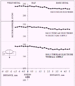
4.4 Micro hardness study
Fig. 7 presents the results of a hardness survey conducted along the central axes of the weld cross-sections made by PESMAW process that compares the two areas of interest in this investigation. The measured hardness in both cases (with & without gas supply) was uniformly distributed and showed less variation within the weld metal. A slight hardness increase was encountered at the fusion boundary in the weldment made by the conventional SMAW process at similar weld conditions. This increase in hardness profile at the fusion boundary between the melt track and heat affected zone was due to a) the change in grain size of the steel and b) the presence of ferrite-bainite structure in HAZ near the fusion boundary.
4 CONCLUSIONS
1. The PESMAW process with gas fed tubular electrodes yielded higher penetration than the conventional SMAW, while the absence of orifice gas resulted in flatter and wider weld beads at specified welding conditions.
2. The penetration depth varies radially with respect to the line of gas flow.
3. There was a noticeable increase in heat input in PESMAW due to the presence of auxiliary plasma generated by the orifice gas.
4. Hardness values showed less variation and uniformly distributed with in the weld metal.
6 REFERENCES
[1].M.P.Jain, Welding & NDT of oil & gas pipelines-productivity & quality issues, National seminar on cost effective welding & productivity, Indian welding society (IWS), New Delhi, India, 2002, 115.
[2]. A.C. Underwood, Automated welding will meet the desperate need for more pipelines in the United States, Welding Design & Fabrication, November 1980, 134-135.
[3].R. L. Klien, Pipelines Design, construction and operation.2, New York, Construction press, 1984, 3-4.
[4].Sunil Pandey, New Technologies in Shielded metal Arc welding and Gas Metal Arc Welding. National Welding Seminar, Indian Institute of Welding (IIW), Chennai, India, 2002.
[5].Sunil Pandey, Tahir I. Khan, S.Thiruchitrambalam, Surface modification of steels using plasma enhanced shielded metal arc welding process (PESMAW), Indian welding journal, April 2003, 27-30.
[6].J. I. Lee, K. W. Um, A prediction of welding process parameters by prediction of back-bead geometry, Journal of Materials Processing Technology, Volume 108, December 2000, 106-113.
[7].R. S. Chandel, et al, Effect of increasing deposition rate on the bead geometry of submerged arc welds, Journal of Materials Processing Technology, Volume 72, December 1997, 124-128.
[8].D. S. Nagesh, G. L. Datta, Prediction of weld bead geometry and penetration in shielded metal-arc welding using artificial neural networks, Journal of Materials Processing Technology, Volume 123, Issue 2, April 2002, 303-312.
[9].S. Kim, J. S. Son, et al., A study on relationship between process variables and bead penetration for robotic CO2 arc welding, Journal of Materials
Processing Technology, Volume 136, Issues 1-3, May 2003, 139-145.
[10]. Widgery, D.J., Line pipe welding beyond 2000, Svetsaren, Esab welding and cutting Journal, No .3, 1999, 8-11.
[11]. S. Kim, J. S. Son, et al., A study on prediction of bead height in robotic arc welding using a neural network, Journal of Materials Processing Technology, Volumes 130-131, 20 December 2002, 229-234.
[12]. S. Kim I., H. Kwon W, E. Siores, An investigation of a mathematical model for predicting weld bead geometry, Canadian Metallurgical Quarterly, Volume 35, October 1996, 385-392.
![Fig. 1 Flow diagram for PESMAW process [5]](https://thumb-ap.123doks.com/thumbv2/123dok/593251.70826/2.595.313.537.86.279/fig-flow-diagram-pesmaw-process.webp)