SUPERVISOR DECLERATION
“I hereby declare that I have read this thesis and in my opinion this report is sufficient in
terms of scope and quality for the award of the degree of Bachelor of Mechanical Engineering (Automotive)”
Signature : ...
Supervisor I : MOHD ADRINATA BIN SHAHARUZAMAN
Date : ...
Signature : ...
Supervisor II : EN. MOHD HANIF BIN HARUN
AN EXPERIMENTAL STUDY OF STEERING WHEEL
VIBRATION IN STATIC CONDITION
MUHAMMAD TAUFIQ BIN ABDUL KHALID
This report is submitted in partial fulfillment of the requirement for the
Bachelor of Mechanical Engineering (Automotive)
Faculty of Mechanical Engineering
Universiti Teknikal Malaysia Melaka (UTeM)
DECLARATION
“I hereby declare that the work in this report is my own except for summaries and quotations which have been duly acknowledged.”
Signature: ...
Author: ...
ACKNOWLEDGEMENT
First, I would like to express my greatest gratitude to Almighty Allah for giving
me a chance to complete my project with all His blessings. I would like to acknowledge
my project supervisor, Mr Mohd Adrinata Bin Shaharuzaman. The fundamental idea of
this project is his and he was a valuable source of information about this project. I am
very thankful that he supervised my work and provided my with the much needed
assistance in understanding the project. Without his guidance and support, I may not be
able to achieve the goals of this project.
To all my lecturers who had thought me this far, very special thanks to them. To
all my friends who gave their support to construct my project. Not forget, I would like to
acknowledge my technician, Mr Hairul Nizam Bin Daud, because helping me in
completing my project. Finally, I would also like to thank my parents, Mr. Abdul Khalid
ABSTRACT
Vibration causes discomfort situation when driving car. Vehicle such as cars are
regularly exposed to vibration. The purpose of this project is to determine the dynamic
properties of steering wheel and to analyze the highest vibration level for Perodua
Kancil in Static condition. The modal analysis method is used to complete this project.
Modal analysis cans analysis the steering wheel vibration characteristic. The limitation
in this project is in static condition with is the experiment will be conduct in free-free
boundary and constraint condition. For the first experiment, modal analysis is use to
determine the natural frequency of 2, 3 and 4 spoke steering wheel in free-free
boundary. The second experiment also will be use modal analysis method to determine
the natural frequency but in constrain condition for 2, 3 and 4 spoke steering wheel. The
third experiment is to analyze the highest vibration level for Perodua Kancil in static
condition. So the result of this project will be the natural frequency of 2, 3 and 4 spokes
steering wheel in free-free boundary and constraint condition. The highest vibration level for Perodua Kancil also will be determined after completing this project. Today’s car is much more comfortable and has improved so much in many ways including in
ABSTRAK
Getaran menyebabkan situasi tidak selesa semasa memandu kereta. Kenderaan
seperti kereta secara umumnya lebih terdedah terhadap getaran. Tujuan projek ini adalah
untuk menentukan sifat-sifat dinamik stereng dan menganalisis tahap getaran tertinggi
bagi Perodua Kancil dalam keadaan statik. Kaedah analisis modal digunakan untuk
menyelesaikan projek ini. Modal analisis akan memberikan ciri-ciri getaran stereng
tersebut. Keterbatasan dalam projek ini adalah dalam keadaan statik dan dilakukan
dalam keadaan bebas dan sekatan . Untuk eksperimen pertama, analisis modal ini
digunakan untuk menentukan natural frekuensi untuk 2, 3, dan 4 spoke stereng
kereta. Eksperimen kedua juga akan menggunakan kaedah analisis modal untuk
menentukan natural frekuensi dalam keadaan sekatan bagi 2, 3, dan 4 spoke stereng
kereta. Eksperimen ketiga adalah untuk menganalisis tahap getaran tertinggi bagi
Perodua Kancil dalam keadaan statik. Jadi hasil keputusan dari projek ini adalah natural
frekuensi untuk 2, 3 dan 4 spoke stereng kereta. Tahap getaran tertinggi bagi Perodua
Kancil juga akan ditentukan selepas menyelesaikan projek ini. Kereta pada hari ini jauh
CONTENT
CHAPTER SUBJECT PAGE
DECLARATION ii
ACKNOWLEDGEMENT iii
ABSTRACT iv
ABSTRAK v
CONTENT vi
LIST OF TABLE xi
LIST OF FIGURE xvi
LIST OF SYMBOL xvii
LIST OF APPENDIX xviii
CHAPTER 1 INTRODUCTION
1.1 Background 1
1.2 Problem Statement 3
1.3 Objectives 3
1.4 Scope 3
CHAPTER 2 LITERATURE REVIEW
2.1 Introduction 4
2.2 History of Steering System 4
2.3 Fundamental of Steering System 6
CHAPTER SUBJECT PAGE
2.3.2 Steering System Component 7
2.3.2.1 Recirculating Ball 8
2.3.2.2 Rack and Pinion 8
2.3.3 Steering Wheel 10
2.3.4 Power Steering 12
2.4 Vibration
2.4.1 Vibration in Humankind daily Life 13
2.4.2 Introduction of Vibration 13
2.4.2.1 Type of Vibration 14
2.4.2.2 Simple Waves of Vibration 15
2.4.3 Vibration on Human 16
2.4.3.1 Hand Arm Vibration (HAV) 17
2.4.3.2 Whole Body Vibration (WBV) 17
2.4.4 Vibration on Vehicle 18
2.4.5 Steering Wheel Vibration 20
2.4.6 Vibration Effect 22
CHAPTER 3 METHODOLOGY
3.1 Background 23
3.2 Experimental Modal Analysis of Steering
Wheel Vibration for Free Free Boundary 26
3.2.1 Objective of the Experiment 26
3.2.2 Apparatus 26
3.2.3 Procedure of Experiment 30
3.2.3.1 Preparation before Experiment 30
3.2.3.2 Measurement of Natural Frequency 31
3.3 Experimental Modal Analysis of Steering
Wheel Vibration for Free Free Boundary
CHAPTER SUBJECT PAGE
3.3.1 Objective of the Experiment 36
3.3.2 Apparatus 36
3.3.3 Procedure of Experiment 40
3.3.3.1 Preparation before Experiment 40
3.3.3.2 Measurement of Natural Frequency 43
3.4 Experimental Modal Analysis of Steering
Wheel Vibration for Constraint Condition 46
3.4.1 Objective of the Experiment 46
3.4.2 Apparatus 46
3.4.3 Procedure of Experiment 49
3.4.3.1 Preparation before Experiment 49
3.4.3.2 Measurement of Natural Frequency 50
3.5 Experimental To Analyze The Highest Vibration
Level For Perodua Kancil In Static Condition 53
3.5.1 Objective of the Experiment 53
3.5.2 Apparatus 53
3.5.3 Procedure of Experiment 56
3.5.3.1 Preparation before Experiment 56
3.5.3.2 Measurement Data 57
CHAPTER 4 RESULT AND DISCUSSION
4.1 Background 60
4.2 Results for Experimental Modal Analysis of
Steering Wheel Vibration for Free-Free
Boundary 61
4.2.1 2-spoke Steering Wheel 61
4.2.2 3-spoke Steering Wheel 63
CHAPTER SUBJECT PAGE
4.2.4 Natural Frequency for 2, 3 and
4-spoke steering wheel for Free-Free
Boundary 67
4.3 Results for Experimental Modal Analysis of
Steering Wheel Vibration for Free-Free
Boundary using Dactron RT Pro 68
4.3.1 2-spoke Steering Wheel 68
4.3.2 3-spoke Steering Wheel 69
4.3.3 4-spoke Steering Wheel 70
4.3.4 Natural Frequency for 2, 3 and
4-spoke steering wheel for Free-Free
Boundary using Dactron RT Pro 71
4.4 Results for Experimental Modal Analysis of
Steering Wheel Vibration for Constraint Condition 74
4.4.1 2-spoke Steering Wheel 74
4.4.2 3-spoke Steering Wheel 75
4.4.3 4-spoke Steering Wheel 76
4.4.4 Natural Frequency for 2, 3 and
4-spoke steering wheel for Constraint
Condition 77
4.5 Results for Experimental Modal Analysis of
Steering Wheel Vibration for Static Condition 80
4.5.1 Idle Condition at 1400 rpm 80
4.5.2 Aircond ON Condition at 1200 rpm 82
4.5.3 3000 rpm 84
4.5.4 The highest vibration level in static
condition 86
4.5.5 Highest vibration level for 2, 3, 4-spoke
CHAPTER SUBJECT PAGE
4.5.6 Highest vibration level for 2, 3 and
4-spoke steering wheel at aircond ON
condition (1200 rpm) 88
4.5.7 Highest vibration level for 2, 3 and
4-spoke steering wheel at 3000 rpm 89
4.5.8 Highest vibration level for 2-spoke
steering wheel at 1400, 1200 and
3000 rpm 90
4.5.9 Highest vibration level for 3-spoke
steering wheel at 1400, 1200 and
3000 rpm 91
4.5.10 Highest vibration level for 4-spoke steering wheel at 1400, 1200 and
3000 rpm 92
4.5.11 Relationship of Natural Frequency 93
CHAPTER 5 CONCLUSION AND RECOMMENDATION
5.1 Conclusion 95
5.2 Recommendation 97
BIBLIOGRAPHY 98
REFERENCE 100
LIST OF TABLE
TABLE TITLE PAGE
4.0 Natural frequency for 2-spoke steering wheel 62
4.1 Natural frequency for 3-spoke steering wheel 64
4.2 Natural frequency for 4-spoke steering wheel 66
4.3 Natural frequency for 2, 3 and 4-spoke steering wheel 67
4.4 Natural frequency of 2, 3 and 4-spoke steering wheel using
RT Pro 71
4.5 Natural frequency of 2, 3 and 4-spoke steering wheel in
constraint 77
4.6 Highest vibration level in static condition condition 86
LIST OF FIGURE
FIGURE TITLE PAGE
1.0 Model T at 1908 by Henry Ford 2
(Source: http://www.auto123.com)
1.1 New Ford Fusion 2010 2
(Source: http://theautomedia.com)
2.0 The vehicle use tiller or handle system 5
(Source: http://www.ausbcomp.com/~bbott/cars/carhist.htm)
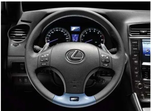
2.1 Modern steering wheel 5
(Source: http://www.muslimrahman.com)
2.2 The vehicle turning with the circular shape 6
(Source: http://auto.howstuffworks.com/steering1.htm)
2.3 Three main part of the steering system 7
(Source: “Total Automotive Technology”, page 885)
2.4 Steering column part 7
(Source: “Total Automotive Technology”, page 885)
2.5 Recirculating ball steering gear 8
(Source: http://auto.howstuffworks.com/steering3.htm)
2.6 A complete rack-and-pinion steering assembly 9
(Source: “Auto Suspension and Steering”, page 19)
2.7 Cutaway of rack-and-pinion steering assembly 9
(Source: “Auto Suspension and Steering”, page 19)
2.8 Early vehicle had use tiller or handle steering 10
FIGURE TITLE PAGE
2.9 A steering wheel at design stage 11
(Source: Yang, Z.Z. et al. (2005))
2.10 Component of a typical steering wheel 11
(Source: Yang, Z.Z. et al. (2005))
2.11 Type of steering wheel 12
(Source: Yang, Z.Z. et al. (2005))
2.12 Power steering system 12
(Source: http://coysdenver.com/service/powersteering.shtml)
2.13 Damage of the machine caused by vibration phenomena 14
(Source: http://www.lindsayengineering.com/services/vibrat
ion-analysis-testing/)
2.14 Free vibration 14
(Source: http://www.mfg.mtu.edu/cyberman/machtool/mach
tool/vibration/intro.html)
2.15 Force vibration 15
(Source: http://www.roymech.co.uk/Useful_Tables/Vibrations
/Forced_Vibrations.html)
2.16 Type of human vibration 16
(Source: http://www.MMF.de)
2.17 Hand arm vibration 17
(Source: http://www.MMF.de)
2.18 Whole body vibration 17
(Source: http://www.MMF.de)
2.19 Vibration transmits from engine to driver 18
(Source: Kim, K.C. et al. (2007))
2.20 Main sources of vibration disturbances in a vehicle 19
(Source: Shayaa, M.S. et al. (2001))
2.21 The case of idle shake and booming noise 20
FIGURE TITLE PAGE
2.22 Vibration modes of steering system 21
(Source: Kim, K.C. et al. (2007)) 3.0 Flow chart of final year project 24
3.1 Test platform with table 26, 36 3.2 Accelerometer 27, 36, 47, 54 3.3 2-spoke 27, 37, 47, 54 3.4 3-spoke 27, 37, 47, 54 3.5 4-spoke 27, 37, 47, 54 3.6 ICP type signal conditioning 28
3.7 5mm nut 28, 38 3.8 Glue 28, 38 3.9 Impact hammer 29, 37, 39, 48 3.10 Rope 29,39 3.11 DEWESOFT software 29
3.12 Affix 5mm nut at steering 30, 40 3.13 Nut position 30, 40 3.14 Connect the accelerometer to the input channel of ICP signal conditioning 31
3.15 Hang up steering wheel 31, 41 3.16 Accelerometer location at 30o and 150o of steering wheel angle 32, 42 3.17 Set the ICP channel 32
3.18 Set the sensetivity for right and left point of accelerometer 33
3.19 Spectrum analyzer mode window 33
3.20 Set up the FFT options 34
3.21 Hit steering wheel 34
3.22 Impact analysis 35
3.23 LDS Dactron Data Aquisition 38, 48, 55
FIGURE TITLE PAGE
3.25 LDS Dactron Data Acquisition connection 41
3.26 Dactron RT Pro interface 45, 52, 59 3.27 Perodua Kancil for experiment 46, 53 3.28 Accelerometer at steering wheel for constraint condition 49
3.29 Accelerometer at steering wheel 56
3.30 Accelerometer at steering column 56
3.31 Accelerometer at steering buck head 56
4.0 Graph of natural frequency for left point – 2 spoke 61
4.1 Graph of natural frequency for right point – 2 spoke 61
4.2 Graph of natural frequency for left point – 3 spoke 63
4.3 Graph of natural frequency for right point – 3 spoke 63
4.4 Graph of natural frequency for left point – 4 spoke 65
4.5 Graph of natural frequency for right point – 4 spoke 65
4.6 Graph of natural frequency for 2-spoke steering wheel 68
4.7 Graph of natural frequency for 3-spoke steering wheel 69
4.8 Graph of natural frequency for 4-spoke steering wheel 70
4.9 1st mode shape steering wheel 72
(Source: Yang, Z.Z. et al. (2005)) 4.10 2nd mode shape steering wheel 72
(Source: Yang, Z.Z. et al. (2005)) 4.11 Mode shape of the system 73
(Source: Avitabile, P. (no date)) 4.12 Graph of natural frequency for 2-spoke steering wheel in constraint condition 74
4.13 Graph of natural frequency for 3-spoke steering wheel in constraint condition 75
4.14 Graph of natural frequency for 4-spoke steering wheel in constraint condition 76
FIGURE TITLE PAGE
(Source: Kim, K.C. et al. (2007))
4.16 1st mode lateral bending 78
(Source: Kim, K.C. et al. (2007)) 4.17 2-spoke: idle condition 80
4.18 3-spoke: idle condition 80
4.19 4-spoke: idle condition 81
4.20 2-spoke: Air Cond ON condition 82
4.21 3-spoke: Air Cond ON condition 82
4.22 4-spoke: Air Cond ON condition 83
4.23 2-spoke: 3000 RPM condition 84
4.24 3-spoke: 3000 RPM condition 84
4.25 4-spoke: 3000 RPM condition 85
4.26 Highest vibration level for 2, 3 and 4-spoke steering wheel at idle condition (1400 rpm) 87
4.27 Highest vibration level for 2, 3 and 4-spoke steering wheel at aircond ON condition (1200 rpm) 88
4.28 Highest vibration level for 2, 3 and 4-spoke steering wheel at 3000 rpm 89
4.29 Highest vibration level for 2-spoke steering wheel at 1400, 1200 and 3000 rpm 90
4.30 Highest vibration level for 3-spoke steering wheel at 1400, 1200 and 3000 rpm 91
4.31 Highest vibration level for 4-spoke steering wheel at 1400, 1200 and 3000 rpm 92
5.0 The International Organization for Standardization (ISO); 96
Guidelines relating magnitude to comfort for passenger on
public transport
LIST OF SYMBOL
HAV = Hand Arm Vibration
WBV = Whole Body vibration
Hz = Hertz
A = Amplitude
f = Frequency, Hz
= Omega
= Pi
a = Acceleration, m/s2
k = Spring constant
cd = Damper constant
m = Mass, kg
x = Displacement, meter
P = Force, N
t = Time, s
ICP = Integrated Circuit Piezoelectric
LIST OF APPENDIX
APPENDIX TITLE PAGE
A 2-spoke Steering Wheel 101
A-1 Left point- 2 spoke steering wheel (2nd punch) 101
A-2 Left point- 2 spoke steering wheel (3rd punch) 101
A-3 Right point- 2 spoke steering wheel (2nd punch) 102
A-4 Right point- 2 spoke steering wheel (3rd punch) 102
B 3-spoke Steering Wheel 103
B-1 Left point- 3 spoke steering wheel (2nd punch) 103
B-2 Left point- 3 spoke steering wheel (3rd punch) 103
B-3 Right point- 3 spoke steering wheel (2nd punch) 104
B-4 Right point- 3 spoke steering wheel (3rd punch) 104
C 4-spoke Steering Wheel 105
C-1 Left point- 4 spoke steering wheel (2nd punch) 105
C-2 Left point- 4 spoke steering wheel (3rd punch) 105
C-3 Right point- 4 spoke steering wheel (2nd punch) 106
C-4 Right point- 4 spoke steering wheel (3rd punch) 106
D Simple Plate Sine Dwell Response 107
E Gantt chart for PSM 1 108
CHAPTER 1
INTRODUCTION
1.1 BACKGROUND
Nowadays, transportation is one of most important element in helping people to
move. Transports give human the freedom to move from one place to another place.
People do not have to told how important the automobile in their live. The automobile
such as car, van and also heavy duty vehicle is used to help people in completing their
daily life activities. The automotive industry was starting about more than 100 years ago.
Years by years, a lot of new technologies grow rapidly. As an example, in 1860, the first
practical Internal Combustion engine has been invented by J.J.E. Lenoir, the engine
technology is grow rapidly within the innovation in our automotive technology.
Increasing of vehicle use over the years has directly increased the design element and
characteristic in the vehicle to achieve more efficiency, cleaner, more economy and
more reliable.
The modern vehicle is totally different from the vehicle of years ago. Vehicle
nowadays are designed to produce fewer emission and less pollution. Modern vehicle
also is more save if compare to the vehicle years ago. The green technology in
automotive industry such as hybrid technology, help to protect our environment from the
pollution of the vehicle. A lot of world brand use the environment issue in creating their
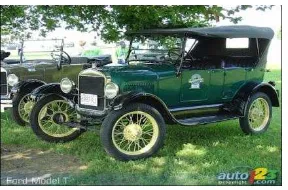
Ford, from the first model, Model T 1908, to the new styling and futuristic model, Ford
Fusion 2010.
Today, an innovation is taking place in steering system technology in automotive
industry. Steering technology in automotive grow rapidly. There have two basic type of
steering system which is recirculating ball and rack and pinion. In the 1950’s, General
Motor introduces the hydraulic assisted power steering system. This system used
recirculation ball system. The rack and pinion steering system, eventually develop and
used in many lighter and sportier vehicle.The steering system is used to control the
direction of the vehicle. The steering system is design to control the direction of the
front wheel over all type of road condition, with through turn and at different speed of
[image:21.612.249.393.144.239.2]the vehicle.
Figure 1.0: Model T at 1908 by Henry Ford (Source: http://www.auto123.com)
[image:21.612.226.433.294.408.2]1.2 PROBLEM STATEMENT
Vibration causes discomfort situation when driving car. Vehicle such as car are
regularly exposed to vibration. In recent research (Kim K.C. et al. 2007), the sources of
vibration include the engine, wheel, tires, and the profile of road surface. The sources of
vibration travel through the engine and the body structure of the car. When the vibration
sensed by the driver through steering wheel, it is described as steering vibration.
1.3 OBJECTIVES
The main objective of these final years project is to conduct experimental modal
analysis of steering wheel vibration for Perodua Kancil 850cc. Two experiments will be
conducted which are free-free boundary and constraint condition. Natural frequency and
the mode shape of the steering wheel will be determined. The next objective is to study
the behavior of steering wheel vibration for 2-spoke, 3-spoke and 4-spoke steering
wheel. The analysis for this experiment are more focusing to this 3 type of spoke which
is can fixed into Perodua Kancil 850 cc steering column. The highest vibration level for
Perodua Kancil at static condition also will be determined.
1.4 SCOPE
The scope of these final year project is:
a) The car type that use in these experiment is national compact car with
automatic transmission, front wheel drive and non-power steering.
b) The experimental analysis for the steering wheel for free-free boundary
condition and constraint condition.
CHAPTER 2
LITERATURE REVIEW
2.1 INTRODUCTION
The automotive industry is one of the most influential technological advances of
this time. People use transportation every day for travel from one place to another place.
This chapter will discuss about how steering system works and what is the vibration of
steering wheel.
2.2 HISTORY OF STEERING SYSTEM
Function of steering system is to control the direction of a vehicle's motion.
Steering system was not needed until the growing of the modern vehicle technology that
follows the time frame of vehicle improvement. Before the modern steering system was
develop, steering consists of getting the animal pulling the vehicle to move in the desire
direction or to change the direction of the vehicle. The earliest vehicle steering system
utilized a tiller or handle, which was connected to the wheel by simple linkage. The
handle worked well when vehicle were small and light, but when the weight and size of
the vehicle increase, its replace with the steering system to multiply the turning force of
Today’s drivers have become accustomed to the fact that steering a vehicle no longer requires much effort. The driver gets a lot of benefit from the hydraulic or electric
power steering systems that are powered by the engine and support even the slightest
steering wheel movement. Modern power steering systems give the driver directs
feedback by instantly responding with the right amount of power corresponding to the
vehicle speed and driving situation. The modern steering system has been improving a
[image:24.612.215.442.95.264.2]lot of driving situation.
Figure 2.0: The vehicle use tiller or handle system. (Source: http://www.ausbcomp.com/~bbott/cars/carhist.htm)
[image:24.612.204.468.486.680.2]