PREDICTING TURBULENT FLOW IN A STAGGERED TUBE
MOHD ADIB MUIZZUDDIN BIN MOHLIS
Laporan ini dikemukakan sebagai
Memenuhi sebahagian daripada syarat penganugerahan Ijazah Sarjana Muda Kejuruteraan Mekanikal (Termal-Bendalir)
Fakulti Kejuruteraan Mekanikal Universiti Teknikal Malaysia Melaka
‘Saya/Kami* akui bahawa telah membaca karya ini dan pada pandangan saya/kami* karya ini
adalah memadai dari segi skop dan kualiti untuk tujuan penganugerahan Ijazah Sarjana Muda Kejuruteraan Mekanikal (Termal-Bendalir)’
Tandatangan :………..
Nama Penyelia I:………..
Tarikh :……….
i
Saya akui laporan ini adalah hasil kerja saya sendiri kecuali ringkasan dan petikan yang tiap-tiap satunya saya telah jelaskan sumbernya”
ACKNOWLEDGEMENT
Alhamdulillah, thanks to ALLAH because I have completed my Projek Sarjana Muda 1 without facing any major problem.
First and foremost I would like to deliver my deep appreciation and thankful my supervisor which is my Heat Transfer Subject lecturer, Encik Shamsul Bahari Bin Azraai for being such a great mentor to me. Much thank and gratitude to Encik Ahmad Kamal Bin Mat Yamin, Mechanical Engineering supervisor for Projek Sarjana Muda, for his good concern. I also would like to thanks my family for encourage and motivate me during this period of industrial training. Besides that I also would like to thank them for financial support.
iii
ABSTRACT
ABSTRAK
v
TABLE OF CONTENT
CHAPTER TITLE PAGE
PENGAKUAN
ACKNOWLEDGEMENT
ABSTRACT
ABSTRAK
TABLE OF CONTENT
LIST OF TABLES
LIST OF FIGURES
LIST OF SYMBOLS
LIST OF ABBREVIATONS
i ii iii iv v viii ix xi xiii
CHAPTER I INTRODUCTION 1
1.1 Predicting Turbulent in a Staggered Tube 1.2 Objective
1.3 Scope
1.4 Problem Statements
1 2 2 2
CHAPTER II LITERATURE REVIEW 4
2.1 Introduction 4
2.2 Computational Fluid Dynamic 5
2.3 Flow Across Cylinder 6
2.31 Drag Force 7
2.32 Correlation for Average Heat Transfer 9 2.4 Factors that Affect the Heat Transfer and Flow
Characteristic across a Cylinder
10
CHAPTER TITLE
2.42 Flow Separation
PAGE
11
2.43 Adverse Pressure Gradient 11
2.44 Wake 12
2.45 Reynolds Number 12
2.5 Flow across Tube Bank 13
2.51 Heat Transfer Coefficient
2.6 Predicting the heat transfer and flow characteristic in a staggered tube by Previous Researchers
2.61 Numerical/CFD simulation in a staggered tube 2.62 Analytical approach
15 16
17 21
CHAPTER III METHODOLOGY 25
CHAPTER IV
3.1 Introduction
3.2 Typical Stage of CFD
3.3 Steps to Generate CFD Simulations using Ansys CFX 3.4 Ansys Workbench
3.41 Geometry 3.42 Meshing 3.5 CFX Pre-Processing 3.51 Type of Simulation 3.52 Domain
3.53 Boundary Condition 3.54 Solver Control 3.6 CFX Solver
3.7 CFX Post Processing
RESULTS AND DISCUSSIONS
4.1 Temperature Profile 4.2 Velocity Profile 4.3 Pressure Profile
4.4 Velocity Vector and Streamline
vii
LIST OF TABLES
TABLE TITLES PAGE
2.1 Parameters used by Incropera et al for staggered tube bank.
23
ix
LIST OF FIGURES
FIGURES
NO
TITLES PAGE
1.1 Fluid flow through a staggered a tube 3
2.1 (a) Points that are arranged in staggered 5
2.1 (b) points that are arranged in inline 5
2.1 (c) Isometric view of a staggered tube 5
2.1 (d) Top view of a staggered tube 5
2.2 Cylinder in cross Flow 6
2.3 Velocity profile indicating flow separation on a cylinder in cross flow
7
2.4 Drag corfficients for circular cylinder and sphere in cross flow
8
2.5 Correlation of heating and cooling for flow across cylinder
9
2.6 Schematic of a tube bank in cross flow (staggered arrangement)
14
2.7 The arrangements for aligned and staggered 14
2.8 Flow conditions for aligned and staggered tubes 16
2.9 Computational grid for tandem cylinder 18
2.10 Boundary conditions by E. Buyruk 19
2.11 Schematic of inline arrangement 21
2.12 Schematic of staggered arrangement 21
2.13 Control volume used by Khan et al for prediction of heat transfer from tube bank
22
3.1 (a) Tube diameter, SL and STvalue for pitch 2.0 28
3.1 (b) Tube diameter, SL and STvalue for pitch 1.8 28
3.1 (c) Tube diameter, SL and STvalue for pitch 1.6 28
3.3 The mesh obtained 30
3.4 The inflation used 30
3.5 Pre processing 31
3.6 Boundary conditions 32
xi
LIST OF SYMBOLS
u = Free stream velocity, m/s
V = Upstream velocity, m/s
ReD = Reynolds Number (for cylinder)
D
C
= Drag Coefficient
h = Heat Transfer Coefficient
D = Tube Diameter, m
K = Thermal Conductivity, W/mC.ºC
v = Kinematic Viscosity, 2 1 m s
Pr = Prandtl Number
C, C m, n 1 = Constant
D
Nu = Nusselt Number
s
= Mean Fluid Velocity, m/s
= Fluid Density, kgm3
= Dynamic Fluid Viscosity, Nsm2
L = Characteristic Length, m
T
S = Transverse Pitch, m
L
S = Longitudinal Pitch, m
D
S = Diagonal Pitch, m
T = Ambient Temperature, °C
1
A = Length from tangent of two tubes in transverse, m 2
A = Length from tangent of two tubes in diagonal, m
T = Temperature, °C
L = Length, m
lm
T
w
= Wall Shear Stress, 2
Nm
w
T = Wall Temperature, °C
Q = Heat Transfer Rate, W
= Distance Normal to and Measured From Surface of Tube,m u = s-component of Velocity in Boundary Layer, m/s
= - component of Velocity in Boundary Layer, m/s
max
xiii
LIST OF ABBREVATIONS
CFD = Computational Fluid Dynamic REV = Representative Elementary Volume RSM = Reynolds Stress Model
RMS = Root Mean Square 2D = Two Dimension 3D = Three Dimension
CHAPTER I
INTRODUCTION
This chapter will explained briefly about predicting turbulent in a staggered tube using computational fluid dynamic, the objective of this study, scopes and the problem statements.
1.1 Predicting Turbulent in a Staggered Tube
The earliest numerical solution in studying steady flow across a circular cylinder was reported during 1933. Since that early work, many studies of flow and heat transfer across tubes and within tube banks have been done using CFD (Computational Fluid Dynamic) software. Heat transfer and flow characteristic prediction across cylinder are important in various engineering aspect and have been presented in many related engineering application. This have been an active research because it have many benefits in practical of heat exchanger tube bundles, flow across overhead cables and for nuclear power plant cooling system.
To obtain the flow characteristic and heat transfer around tube bundles, Navier Stokes and Energy equation can be used to calculate them. Better degree of approximation can be obtain depending on many factors including the solution method, mesh size, boundary condition and the stability and convergence criteria. Although there are many experiment and data that had been done and collected by previous researchers, it is yet possible to get a clear view about the flow and heat transfer process across tube bundles because of its complex geometry and there are many large number of parameter involved.
2
make rather than laminar flow because the turbulence flow field are always unsteady (random, swirling, vertical structures called turbulence eddies). There are many ways to solve the CFD calculation such as Finite Element Method, Direct Numerical Simulation and Large Eddy Simulation. Finite Element Method will be used for the CFD calculation in this study because the CFD software chooses are based on the FEM.
1.2 Objective
The objectives of this study are to predict the heat transfer and flow distribution of a staggered tube.
1.3 Scopes
Design CFD staggered tube geometry.
Simulate air and water through an array of heated staggered tube.
1.4 Problem Statement
To simulate a flow across staggered tube, many parameters have to be decided. These parameters will affect the simulation results. There several parameters that must be considered for predicting turbulent in a staggered tube which are:
Longitudinal and transverse pitch Reynolds Number
Thermal and wall boundary condition
Number of rows Fluid properties Tube diameter
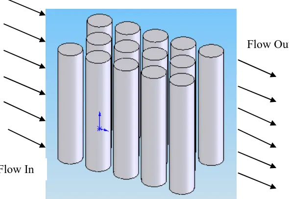
Figure 1.1 shows the fluid flow through a staggered tube. The flow enters at exactly normal to the tube. The detailed boundary condition will be shown in methodology chapter.
Figure 1.1: Fluid flow through a staggered a tube Flow In
4
CHAPTER II
LITERATURE REVIEW
This chapter will explain in detail about the flow across cylinder and tube bank and the formula used. It also includes the previous studies that have been done by previous researchers.
2.1 Introduction
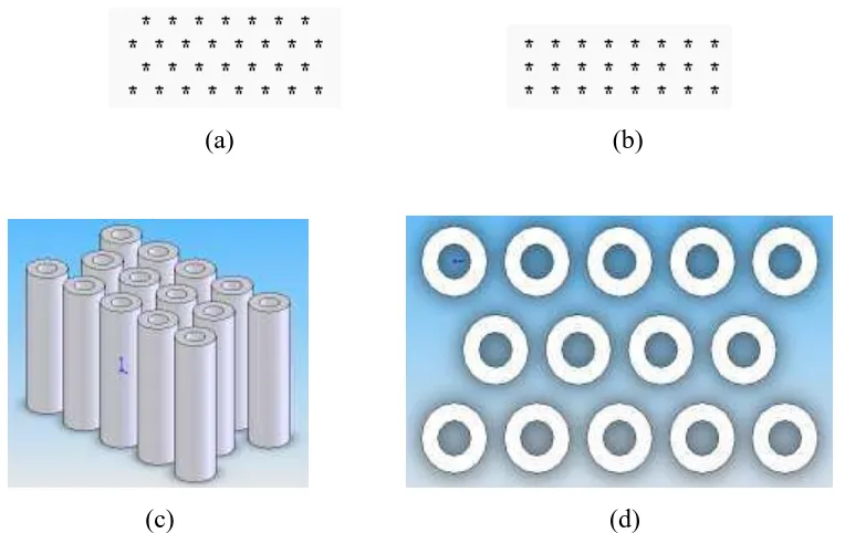
(a) (b)
(c) (d)
Figure 2.1: Shows the points that are arranged in staggered (a) and inline (a) while (c) and (d) shows the isometric view and top view of a
staggered tube
Staggered tube is important in many industrial applications. As mentioned in the introduction chapter, it can be used in nuclear power plant, steam generation in a boiler and coil of an air conditioner. Many studies have been done because of its potential and importance in heat exchanger. In this study the staggered tube bank will be study numerically using CFD package software Ansys CFX.
2.2 Computational Fluid Dynamic
6
2.3 Flows across Cylinder
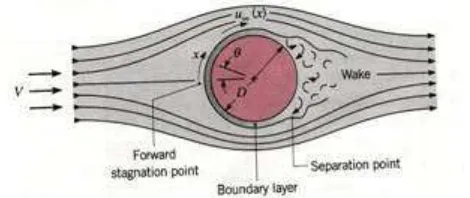
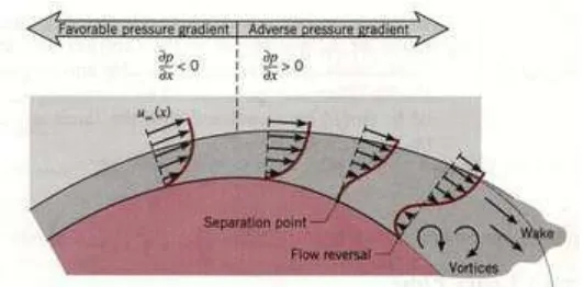
Heat transfer occurs by a cylinder cross flow is as important as heat transfer through flat plates and inside a tube. The heat transfer characteristic is affected by the development of boundary layer on the cylinder. However pressure gradient is important in the analysis and must be included because it influences the boundary layer velocity profile. It also causes a separated flow region that develops at the back of the cylinder when the free stream velocity, u is large. From figure, the fluid is bought to the forward stagnation point with increasing in pressure. From the boundary layer theory the pressure through the boundary layer is constant at any position of the body. But for cylinder case, from the forward stagnation point the pressure will decrease due to increasing of x which is the streamline coordinate and this condition will develop a boundary layer because of the favorable pressure gradient (dp/dx< 0). The upstream velocity, V and u is differ from each other. The free stream velocity depends on the distance x (refer Figure 2.2) from the stagnation point. When free stream velocity equals to zero, which is at the stagnation point the adverse pressure gradient (dp/dx> 0) will make the fluid accelerates and reaches a maximum velocity when dp/dx= 0 (at the symmetrical line of the cylinder). Note that the pressure will start increasing when it reaches the starting of the back of the cylinder and the fluid will decelerate due to the adverse pressure gradient. During this situation, the velocity is maximum and the fluid will start decreasing. As the fluid decelerates, the velocity gradient at the surface becomes zero. Figure 2.2 and Figure 2.3 show the flow across cylinder and its velocity profile that shows the velocity separation [10 and 11].
Figure 2.3: Velocity profile indicating flow separation on a cylinder in cross flow
This makes the fluid near to the surface does not have enough momentum to overcome the pressure gradient and will result a separation point ([ u/ y]y0 0). Separation point is a condition where the boundary layer detaches from the surface and wake is occurring in the downstream region. Reverse phenomena of the fluid occurs as it pass the separation point [10].
Usually laminar boundary layer will develop at the front of the cylinder and turbulent boundary layer will develop at the back of the cylinder [11]. But there is also possibility that a transitional boundary layer will develop in between these two boundary layers and this is depends on the Reynolds Number. If the 5
ReD 2 10x the boundary layer remains laminar but whenReD2 10x 5, transition boundary layer occurs and the separation will be delayed [10].
2.31 Drag Force
This repeatedly process will influence the drag force to the cylinder. It has two components which are:
Friction Drag (due to boundary layer surface shear stress).
8
A drag coefficient can be defined as:
2 ( / 2)
D D
f F C
A V
(2.1)
Figure 2.4 shows the drag coefficient versus Reynolds number graph for flow across circular cylinder and sphere for comparison.
Figure 2.4: Drag corfficients for circular cylinder and sphere in cross flow
2.32 Correlation for Average Heat Transfer
There are actually 3 correlation equations for average heat transfer of flow across cylinder. The equations are stated below.
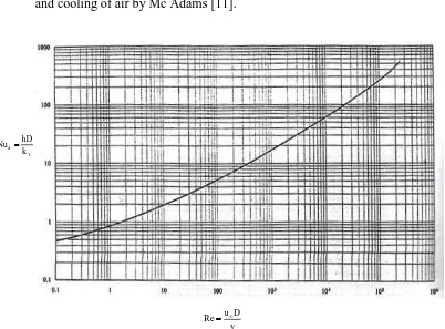
1. The first equation is the easiest to use from a computational standpoint. Figure 2.5 shows the correlated data of a number of investigators for heating and cooling of air by Mc Adams [11].
d f hD Nu k
Re u D
v
Figure 2.5: Correlation of heating and cooling for flow across cylinder [10]
The resulting correlation for average heat transfer is:
1/ 3 Pr n d f f f u D hD Nu C k v
(2.2)