710
SPACE VECTOR ANALYSIS IN ELECTRICAL DRIVES FOR
SINGLE-PHASE INDUCTION MOTOR USING
MATLAB/SIMULINK
1ANGGUN ANUGRAH, 2MARIZAN BIN SULAIMAN, 3 ROSLI OMAR
Faculty of Electrical Engineering, Universiti Teknikal Malaysia, Melaka,Malaysia
Email: [email protected]
ABSTRACT
Space Vector Pulse Width Modulation (SVPWM) has become the successful techniques to construct three-phase sine wave Voltage Source Inverter (VSI) parallel to control three-three-phase motor using vector control. In this paper we present the analysis of SVPWM to construct two-phase sine wave VSI for single-phase induction motor. We also describes the modulation technique refer to dq components of main and auxiliary windings of single-phase induction motor. The VSI have four legs for this single-phase induction motor, and the four switching sequences had simulated in MATLAB and SIMULINK. The simulation result shows the feasibility of the proposed modulation techniques to drive single-phase induction motor.
Keyword:Space vector pulse width modulation (SVPWM), single-phase induction motor (SPIM), matlab, simulink,.
1 INTRODUCTION
The single-phase induction motors have been widely employed in low or middle power level fields, especially in households where a three-phase supply is not available. The terms single or two-phase configurations refer to the supply voltage systems applied to the windings terminals. Single-phase AC can be constructed as induction motors, permanent magnet motors or synchronous reluctance motors. Naturally, a single-phase AC motor will exhibit just a pulsating-in-time air-gap field and consequently a pulsating torque. Thus, an auxiliary field has to be present in order to obtain a revolving air-gap field and electromagnetic torque with an average value different from zero. The solutions employed to create the auxiliary field assume either unsymmetrical stator windings or, supplementary impedances that can be fixed values or electronically controlled. A two-phase AC motor can have a configuration identical to the single-phase version of the motor, but the voltage applied to the windings terminals are independently controlled so that we have a two-phase supply voltage system. As the AC mains are available as single or three-phase systems, a two-phase voltage system is realized through the use of inverters with different control strategies [1].
The Pulse Width Modulation (PWM) makes the inverter output the waveforms made up of many pulses with certain rules and goals through supplying DC voltage for the inverter. Since it is the task for DC/AC switching mode to produce a sinusoidal AC output voltage so as to make the flux linkage and frequency can be controlled with ease, PWM has become the soul of adjusting speed drive systems. Among many forms of PWM, the SPWM and SVPWM are the most common two forms, among which the former is more familiar and the later becomes mature promptly especially in middle and high power systems[2]. Compared to the sinusoidal pulse width modulation (SPWM), SVPWM is more suitable for digital implementation and can increase the obtainable maximum output voltage with maximum line voltage approaching 70.7% of the DC link voltage (compared to SPWM’s 61.2%) in the linear modulation range. Moreover, it can obtain a better voltage total harmonic distortion factor [3].
711
motors), and the potential for leading to a comparison with three-phase induction motor drives. Orthogonal axes direction for each winding was chosen to be the same as the magnetization axes direction, see Fig. 1, thus it will be an identical meaning for stator variables in d-q and physical coordinates.
• Expressions like q-axis winding or main
winding must be seen as equivalents in future paragraphs. All equations are reported to the same stator reference frame (ds-qs), the only system capable of removing the mutual inductances - mechanical angle dependency.
Thereafter, the next steady-state model arrives [6]
:
(1.1)
In (1.1) above, the significance for each variable is:
, , , , , : the supply
voltages across windings in stator and the currents through all four windings (including rotor equivalents) - phasors;
, , , : total winding
impedances, being the sum between resistance and total reactance, the last being further formed by leakage and magnetizing part;
, : magnetizing reactance for the
main, respective auxiliary axis (part of the total reactance);
n : windings turns ratio, defined as the ratio between the number of turns in auxiliary windings and number of turns in main winding, always greater or equal to 1;
number of pole pairs. Several approximations are made for SPIM model, such as: stator windings present a sinusoidal distribution across stator circumference; the motor is mechanically symmetrical while the number of slots for each winding differs from one to another, magnetic material is linear and iron permeability is infinite.
3. SPIM SUPPLIED WITH VARIABLE
FREQUENCY
Although the majority of electrical motors are initially intended to work at a fixed (rated) frequency, the SPIM acceptance for variable frequency supply is even more affected by the existence of a running capacitor in series with auxiliary winding. Rating of the capacitor is a complex process, influenced by load shape and operating speed. Any adjustment in speed implies modifications of the frequency in the supply voltage system, leading further to changes in external reactance introduced by the
running capacitor. This will have an important
influence on efficiency, average, torque and
712
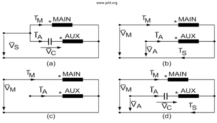
Fig. 2: Four basic solutions for single- phase motor supply
For this study the motor model from (1.1) was engaged, and at this level no limitation for the supply voltages exists. What is important now is to conclude over SPIM behavior when supplied with variable frequency, with and without running capacitor, and with different kinds of voltage systems applied across the windings. Fig. 2 comprises the possible variants of supplying a single-phase motor. The popular method today in variable speed drives [4] and [5], consists in a classical structure of induction motor supplied from a voltage source with variable frequency and amplitude.
4. SPACE VECTOR MODULATION FOR TWO PHASE INVERTER
For variable speed control, the voltage applied to the main and auxiliary windings should be of variable frequency and such magnitude and phase orientation as to maintain the winding currents in time quadrature at all times. One of the approaches to achieve this would be to use PWM bridge so as to create the required fundamental ac voltage. An alternative approach is to use 6 switches three-phase PWM, connecting the two motor windings as an unbalanced load between two phases, as shown
in Fig. 2. This is a more cost effective solution, especially when it is recognized that 6 elements of power electronic switches are now available as a single power electronic module for the power levels of interest (less than a few kW). Note however that the switch rating must be
increased by compared to the rated motor
current, since the center phase carries the sum of the both winding currents which is not zero (unlike a three-phase winding neutral connection). In practice, this will not be a significant limitation for low power motor, given the ratings of present day power electronic switches.
In order to control a single-phase motor with such a converter configuration, it is necessary to determine how the motor will respond to a variable supply frequency across both windings, and determine modulation strategy that most effectively achieve the objective of maintaining quadrature winding currents at any fundamental frequency. Alternatively, for a simple controller, it will probably be easier to modulate for
quadrature voltages across the windings,
correcting for any difference between the winding impedance angles.
Fig. 3 Two-phase Voltage Source Inverter for
713
Fig. 3: Two Phase Voltage Source Inverter for Single Phase Induction Motor
[ ]
100
1
V
r
[ ]
010
2V
r
[ ]
101
4
V
r
[ ]
011
3
V
r
[ ]
000
0V
r
[ ]
111
5V
r
dc
V
V
refmain
V
aux
V
714
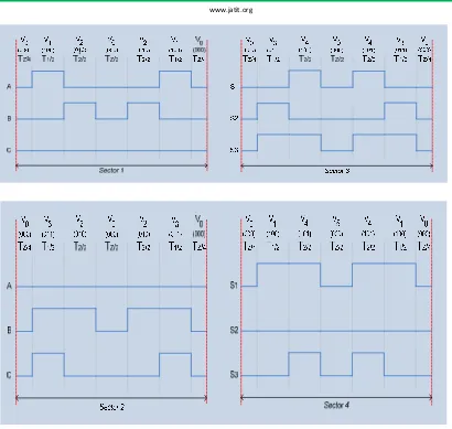
Fig. 5 : Shows space vector PWM switching patterns at each sector
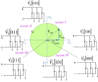
Fig. 3 shows two-phase VSI connected to the two-phase motor. There are sixth switching states: four active states and two zero states in the two-phase inverter, as shown in Fig. 4.
The rotating voltage vector within the four sectors can be approximated by sampling the vector and switching between different inverter states during the sampling period. This will produce an approximation of the sampled rotating space vector. By continuously sampling the rotating vector and high-frequency switching, the output of the inverter will be a series of pulses that have a dominant fundamental sine-wave component, corresponding to the rotation frequency of the vector [10].
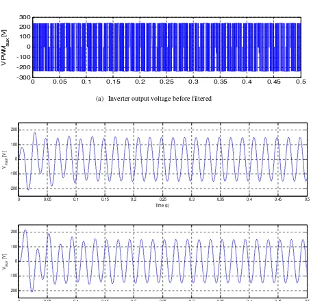
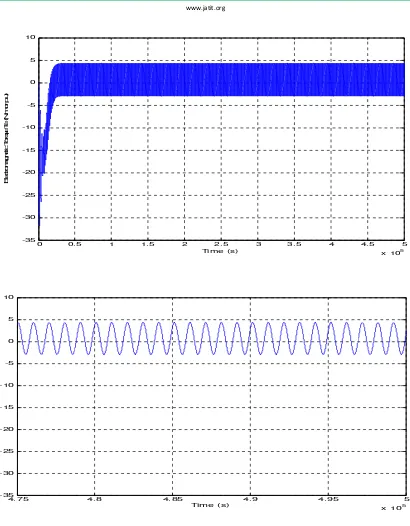
5. SIMULATION RESULTS AND ANALYSIS
The proposed two-phase SVPWM inverter to drive the single-phase induction motor has been simulated using MATLAB/SIMULINK. It assumed that the model motor has Pn = 0.25HP, Vn = 240V (Vrms), f = 50Hz, Rs = 2.02 Ohm, LIs = 7.4mH, Rr’ = 4.12 Ohm, LIr’ = 5.6mH, Lms = 0.1772H
RS = 7.14, LIS = 8.5mH. SVPWM inverter has fs
= 10 kHz, with m = 9.8.
715
0 0.05 0.1 0.15 0.2 0.25 0.3 0.35 0.4 0.45 0.5 -300
-200 -100 0 100 200 300
V P
W
M au
x
[V
]
(a) Inverter output voltage before filtered
0 0.05 0.1 0.15 0.2 0.25 0.3 0.35 0.4 0.45 0.5
-200 -100 0 100 200
Vma
in
[V
]
Time (s)
0 0.05 0.1 0.15 0.2 0.25 0.3 0.35 0.4 0.45 0.5
-200 -100 0 100 200
Vau
x
[V
]
Time (s)
716
0 0.5 1 1.5 2 2.5 3 3.5 4 4.5 5
x 105 -35
-30 -25 -20 -15 -10 -5 0 5 10
Time (s)
E
le
ct
ro
m
a
g
n
e
ti
c
T
o
rq
u
e
T
e
(N
.m
o
r p
.u
)
4.75 4.8 4.85 4.9 4.95 5
x 105 -35
-30 -25 -20 -15 -10 -5 0 5 10
Time (s)
717
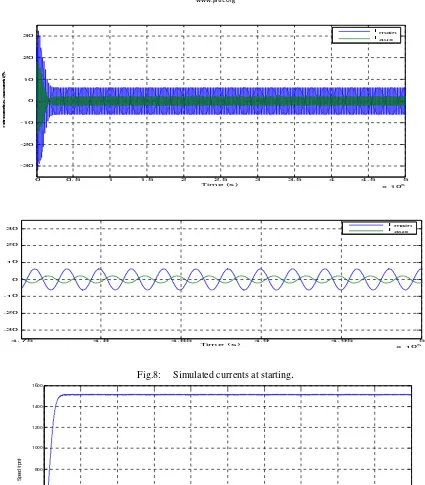
0 0.5 1 1.5 2 2.5 3 3.5 4 4.5 5 x 10⁵ -30
-20
Time (s )
4. 75 4. 8 4. 85 4. 9 4. 95 5
x 105
-30 -20 -10 0 10 20 30
Time (s )
I main
I
aux
Fig.8: Simulated currents at starting
.
0 0.5 1 1.5 2 2.5 3 3.5 4 4.5 5
x 105 0
200 400 600 800 1000 1200 1400 1600
Time (s)
S
p
eed
(
rpm
)
718
6. CONCLUSION
In this paper the space voltage vector pulse width modulation technique is proposed to drive single-phase induction motor. Such technique is applied to adjustable speed control of single-phase induction motor drives. There are four space voltage vectors and two zero vectors in the two-phase inverter. The switching sequence of the two-phase SVPWM is proposed. This technique actually can utilize 100% DC source since there is no center tap from the dc source, and allow index modulation greater than 1 (enable over modulation). This technique proposed to eliminate the using of capacitor to running the motor.
7. ACKNOWLEDGEMENTS
“This work was supported primarily by the Fundamental Research Grant Scheme (FRGS), Project code: FRGS/2007/FKE (1)-F0003.”
REFERENCES
[1] M. Popescue, “Analytical prediction of the electromagnetic torque in single-phase
and two-phase AC motors” Helsinki
University of Technology, laboratory of Electromechanics. Helsinki, 2004.
2] Bai Hua, et al, “Comparison of Three
PWM Strategies – SPWM, SVPWM &
One-cycle Control” Power Electronics
and Drive Systems, 2003. PEDS 2003. The Fifth International Conference on Volume 2, 17-20 Nov. 2003 Page(s):1313 - 1316 Vol.2.
[3] Wei-Feng Zhang and Yue-Hui Yu,
“Comparison of Three SVPWM
Strategies” Journal of Electrical Science
and Technology of China, Vol. 5. No.3, September 2007. pg. 283 -287.
[4] P. C. Krause, 0. Wasynczuk, and S. D. Sudhoff, “Analysis of electric machinery”, IEEE Press, Piscataway, N.J., 1996, ISBN 0-7803-1 101-9, pp. 415 -447.
[5] H. Kragh, Modelling, analysis and
optimisation of power electronic circuits
for low-cost drives, Ph.D. Thesis, Aalborg
University - Denmark, Institute of Energy Technology, February, 2000.
[6] Frede Blaabjerg, et. al, “Comparison of
Variable Speed Drives for Single-Phase
Induction Motors”. Power Conversion
Conference 2002, PCC Osaka 2002, Proceedings of the Volume 3, 2-5 April 2002 Page(s):1328-1333 vol. 3.
[7] E. R. Collins Jr., and R. E. Ashley 111, ”Operating characteristics of single-phase capacitor motors driven from
variable frequency supplies”, Proceedings
of Industry Applications Society Annual Meeting, 1991, p. 52 -57, vol. 1.
[8] H. W. van der Broeck, H.C. Skudelny,
and G. Stanke, “Analysis and realization of a pulse width modulator based on
voltage space vectors”, IEEE Trans. Ind.
Applicat., vol. 24, pp. 142–150, Jan. /Feb.
1988.
[9] A. Boglietti, et al, “Different PWM
Modulation Techniques Indexes
Performance Evaluation”, in IEEE IAS
1993 Conference Record, pp. 193-199.
[10] Zhou, K. and Wang, D., “Relationship
between space vector modulation and three-phase carrier-based PWM: A
comprehensive analysis”. IEEE Trans.
Ind. Electron. 49, 186–196. 2002.
[11] P. C. Krause, “Simulation of
Unsymmetrical 2-Phase Induction
Machines”, IEEE Transactions on Power
719
Prof Dr Marizan Sulaiman obtained his B.sc., M.E.E. and Ph.D. in Electrical from University Of Missouri-Columbia (UMC), USA in 1984, 1985 and 1989. Currently he is the Dean of Faculty of Electrical, University Technical Malaysia Malacca. His research interests including all area of power systems, energy efficient systems, control and instrumentation and e-learning.