DEVELOPMENT OF OPTIMAL PHOTOSENSORS BASED HEART PULSE DETECTOR
NOOR AZLIN BT ZAINAL ABIDIN
This report is submitted in partial fulfillment of the requirements for the award of Bachelor of Electronic Engineering (Industrial Electronics) With Honors’
Faculty of Electronic and Computer Engineering Universiti Teknikal Malaysia Melaka
UNIVERSTI TEKNIKAL MALAYSIA MELAKA
FAKULTI KEJURUTERAAN ELEKTRONIK DAN KEJURUTERAAN KOMPUTER
BORANG PENGESAHAN STATUS LAPORAN
PROJEK SARJANA MUDA II
mengaku membenarkan Laporan Projek Sarjana Muda ini disimpan di Perpustakaan dengan syarat-syarat kegunaan seperti berikut:
1. Laporan adalah hak milik Universiti Teknikal Malaysia Melaka.
2. Perpustakaan dibenarkan membuat salinan untuk tujuan pengajian sahaja.
3. Perpustakaan dibenarkan membuat salinan laporan ini sebagai bahan pertukaran antara institusi
pengajian tinggi.
4. Sila tandakan ( √ ) :
SULIT* *(Mengandungi maklumat yang berdarjah keselamatan atau kepentingan Malaysia seperti yang termaktub di dalam AKTA RAHSIA RASMI 1972)
TERHAD** **(Mengandungi maklumat terhad yang telah ditentukan oleh organisasi/badan di mana penyelidikan dijalankan)
TIDAK TERHAD
Disahkan oleh:
__________________________ ___________________________________
(TANDATANGAN PENULIS) (COP DAN TANDATANGAN
iii
“ I hereby declare that this report is the result of my own work expect for quotes as cited in the references”
iv
“I hereby declare that I have readthis report and in my opinion this report is sufficient in terms of the scope and quality for the award of Bachelor of Electronic
Engineering (Industrial Electronics) with Honors”
v
This thesis had dedicated to my parents and my supervisor who have supported me all
the way since the beginning of my study. Other than that, this thesis also dedicated to my
vi
ACKNOWLEDGEMENT
The success of any project depends on the encouragement and guidelines from many peoples. By inferiority, I would like to express a lot of thanks and great appreciation to the people who had been instrumental in the progressive to complete this project.
Special thanks to my supervisor, Nik Mohd Zarifie Bin Hashim and Khairul Muzzammil Bin Saipullah for guiding me towards the journey of completing this project. Gaining knowledge on various things has greatly increased my confidence in doing this project. The co-operation is much indeed appreciated.
My grateful also to my family and friends for giving me full support towards the end. Your supports have motivated me in many instances. Without your full supports and cooperation, it would be impossible to prepare this report.
vii
ABSTRAK
viii
ABSTRACT
ix
TABLE OF CONTENTS
CHAPTER DESCRIPTION PAGE
Project Title i
Approval ii
Pages of Admission iii
Supervise Conformation iv
List Of Abbreviations xvii
x
2.3 Comparison result for case study 19
2.4 Present work 25
2.5 Summary 26
3 METHODOLOGY 28
3.1 Introduction 28
3.2 Flow chart of the project process 29
3.2.1 Explanation 30
3.3 Hardware Development 30
3.3.1 Finger probe positioning 30
3.3.2 Microcontroller 32
3.3.3 PIC16F877A 34
3.3.4 PIC programmer 36
xi
3.3.6 LM358 low power dual operational amplifier 41 3.3.7 Circuit heartbeat sensor 42
3.3.8 LCD display 43
3.4 Software Development 45
3.5 Summary 49
4 RESULT AND ANALYSIS 50
4.1 Circuit Simulation 50
4.1.1 Simulation of circuit PIC 16f877A and LCD 50
4.3 Experiment using MATLAB 57
4.4 Result from Oscilloscope 60
4.5 Product 67
5 CONCLUSION AND RECOMMENDATION 68
5.1 Conclusion 68
5.2 Problem 69
xii
References 71
Appendix’s
Appendix 1 Appendix2 Appendix3 Appendix4 Appendix5 Appendix6
xiii
LIST OF FIGURES
NO TITLE PAGE
Figure 1.1 Electromagnetic spectrum 2
Figure1. 2 Visible Light 3
Figure 1.4 Overview Of Photodetector 5
Figure 1.10 Flow of the project 10
Figure 2.2.1 Block diagram of the measuring devices 13
Figure 2.2.2 Technique the finger position 14
Figure 2.2.3 Combination of Red LED And IR Sensor as Transmitter
15
Figure 2.2.4 Block diagram of the data system 16 Figure 2.2.5.a Diagram by using Reflectance
Photoplethysmogram
17
Figure 2.2.5.b Reflectance mode PPG 18
Figure 3.2 Flowchart of the project 29
Figure 3.3.2.1 Hardware Circuit 32
Figure 3.3.2.2 Schematic PIC microcontroller 33
Figure 3.3.3.1 PIC 16F877A 34
Figure 3.3.3.2 The PIC 16F877A pin diagram 35
Figure 3.3.4 Connection of cable to box header 37
Figure 3.3.5.1 Basic op-amp 38
Figure 3.3.5.2 Inverting op-amp circuit: 39
Figure 3.3.5.3 Non-inverting op-amp circuit: 40
Figure 3.3.5.4 Unity follower op-amp circuit: 40
Figure 3.3.6 LM 358 pin diagram 41
Figure 3.3.7 Circuit for heartbeat sensor 42
xiv
Simulation of circuit PIC 16f877A and LCD Simulation of circuit LM358
Power supply simulation
50 51 53
Figure 4.1.4 Probe sensor simulation part 54
Figure 4.2.1 Sensitivity of a Photosensor 55
Figure 4.3.1 Example pulse from the probe sensor (WR_5mm) 58 Figure 4.3.2 Digital signal probe sensor with finger 58 Figure 4.3.3 Digital signal probe sensor without finger 59
Figure 4.3.4 Delay test for 10ms 59
Figure 4.3.5 Signal from probe sensor after complete connection 60 Figure 4.4.1 Graph result from LED (red color) and LDR
photosensor
60
Figure 4.4.2 Graph result from LED (green color) and LDR
photosensor 61
Figure 4.4.3 Graph result from Infrared (IR) and Photodiode 61
Figure 4.4.4 No finger on the sensor 62
Figure 4.4.5 Movement factor 62
xv
xvi
LIST OF TABLES
NO TITLE PAGE
Table 1.1 Range of wavelengths color in the visible spectrum 4 Table 2.3.1 The advantage and disadvantage of each Case Study 19 Table 2.3.2 The finger position of each Case Study 21 Table 2.3.3 Comparison between each photosensor heart pulse
detector
24
Table 3.3.1 Finger probe positioning criteria 31
Table 3.3.3.1 Specification of PIC 16F877A 35
Table 3.3.3.2 PIN name and their application 36
Table 3.3.8 Pin connection of LCD display 44
Table 4.2.2 Table shows the output from the LM358 52 Table 4.2.1.1 Sample measurement result from various type of
LED and IR sensor
56
Table 4.2.1.1 Test using three types of paper color 57
xvii
LIST OF ABBREVIATIONN
PIC Programmable Integrated Circuit LCD Liquid Crystal Display
Bpm Beat per minute
HR Heart Rate
LED Light Emitting Diode
IR Infrared
LDR Light Dependent Resistor PIR Passive Infrared
ADC Analog to Digital signal
OSC Oscilloscope
ECG Electro-cardiogram
IEEE The Institute of Electrical and Electronics Engineers HBMD heart beat monitoring device
PPG mode Photoplethysmography
CdS Cadmium Sulfide
CO Carbon Monoxide
CHAPTER 1
INTRODUCTION
1.1 Review of electromagnetic spectrum
2
Figure 1.1 : Electromagnetic spectrum
Moreover, the electromagnetic waves generated from the motion of electrically charged which called as ‘electromagnetic radiation’ that produced from oscillating electric and magnetic fields. The wave of energy generated via vibrations moves through the space by using the speed of light. The visible light is one form of electromagnetic (EM) radiation.
1.2 Visible Light
3
wavelength. The red color has the longest wavelength and the violet color has the shortest wavelength. The combination of all color will produce white color.
Figure 1.2 : Visible light waves
4
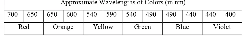
Table 1.1 : Range of wavelengths color in the visible spectrum
Approximate Wavelengths of Colors (in nm)
700 650 650 600 540 590 540 490 490 440 440 400
Red Orange Yellow Green Blue Violet
1.3 Infrared Radiation
5
1.4 Photodetector
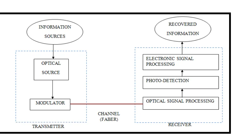
Figure 1.4 : Overview of Photodetector
Figure 1.4 shows the process flow of how to convert optical signal into an electrical signal. In other words, the detectors receive transmitted optical pulse and converted weather to electronic signal processing, photodetection or optical signal processing. Apart from that, the photodetectors are suitable to be use in optical communication system.
6
cost. From the researched, there are many types of photodetector, which are photoconductive cell, also called as light dependent resistor (LDR) or as photocell. Other types of photodetector are photovoltaic detector, photodiode and phototransistor.
1.5 Significant of Oxygen Saturation
Oxygen (O2) is an important part in human body. Without O2 each cell in the
human body cannot function and will be damaged. When the oxygen flows into the lungs, it will pass on into blood. The blood will carry the oxygen to the each organ in human body. For example, the Oximetry is a device that measures the oxyhemoglobin (HbO2) Saturation in blood. It measured by using a basic concept which is the light will
transmit through a blood. After that it will determine the amount of light absorbed by oxygenated and deoxygenated hemoglobin. In addition, the oxygenated blood especially red color whereas deoxygenated blood has a dark blue coloration. Physically, the blood was detected when the finger placed on the probe. The light will pass through the finger to reach the detector. The amount of light that absorbed in finger depends on some factors such as concentration of the light, length of light path, oxyhemoglobin and deoxyhemoglobin.
The optical property of blood in the visible and near –infrared spectral regions depends on the amount of O2 carried by blood. Otherwise, the absorption of the light
7
1.6 Project Background
The ‘Development of Optimal Photosensors Based Heart Pulse Detector” project consists of a photosensor which is used to measure the pulse by measuring the change in blood flow. The research concern is to review the best photo-sensor such as Light Emitting Diode (LED), Infrared (IR), and Light Dependent Resistor (LDR), need to be used in order to produce significant heart pulse signal detected from human finger. The biggest significant between the wavelength is the best of photosensor.
Other than that, this project also used microcontroller where the microcontroller will be programmed to calculate the heart rate and control the LCD display to indicate the pulse rate. The heart pulse will be display on a LCD display for easy monitoring.
1.7 Objective of Project
The objectives of this project as below:
i. To develop a biggest significant between photosensor (LED, IR and LDR) by using a suitable testing.
ii. To develop a simple equipment that is easy to use and make sure each person can monitor their health everywhere