BROADBAND X-CIRCULAR POLARIZED ANTENNA
SITI LAILATUL QADR BINTI ZULKIPLI
This Report Is Submitted In Partial Fulfillment of Requirement for the Bachelor of Electronic Engineering (Wireless Communication)
With Honours
Faculty of Electronic and Computer Engineering Universiti Teknikal Malaysia Melaka
UNIVERSTI TEKNIKAL MALAYSIA MELAKA
FAKULTI KEJURUTERAAN ELEKTRONIK DAN KEJURUTERAAN KOMPUTER
BORANG PENGESAHAN STATUS LAPORAN
PROJEK SARJANA MUDA II
Tajuk Projek : BROADBAND X-CIRCULAR POLARIZED ANTENNA
Sesi
Pengajian : 1 1 / 1 2
Saya SITI LAILATUL QADR BINTI ZULKIPLI
mengaku membenarkan Laporan Projek Sarjana Muda ini disimpan di Perpustakaan dengan syarat-syarat kegunaan seperti berikut:
1. Laporan adalah hakmilik Universiti Teknikal Malaysia Melaka.
2. Perpustakaan dibenarkan membuat salinan untuk tujuan pengajian sahaja.
3. Perpustakaan dibenarkan membuat salinan laporan ini sebagai bahan pertukaran antara institusi pengajian tinggi.
4. Sila tandakan ( √ ) :
SULIT* *(Mengandungi maklumat yang berdarjah keselamatan atau kepentingan Malaysia seperti yang termaktub di dalam AKTA RAHSIA RASMI 1972)
TERHAD** **(Mengandungi maklumat terhad yang telah ditentukan oleh organisasi/badan di mana penyelidikan dijalankan)
TIDAK TERHAD
Disahkan oleh:
__________________________ ___________________________________
(TANDATANGAN PENULIS) (COP DAN TANDATANGAN PENYELIA)
“I hereby declare that this report is result of my own effort except for quotes as cited in the references.”
Signature : ……….
“I hereby declare that I have read this report and in my opinion this report is sufficient in terms of the scope and quality for the award of Bachelor of Electronic
Engineering (Wireless Communication) with Honours.”
Signature : ……….
This project are dedicated to my dearest parent,
Zulkipli Bin Ahmad and Rusimah Binti Ahmad, my siblings, and not forget to my friends,
who have always sincerely pray for my success and glory.
To my supervisors,
thank you for your care and taught so that this task can be accomplished
ACKNOWLEDGEMENT
In the name of Allah S.W.T, The Most Beneficial and The Most Merciful. It is with deepest serve gratitude of the Al-Mighty that gives me strength and ability to complete this final year project report. It has been a pleasant and knowledgeable
journey in preparing this thesis.
First of all, I would like to take this opportunity to express my special thanks to my supervisor, Mr. Abd Shukur Bin. Ja’afar and my co-supervisor Mr. Mohamad Zoinol Abidin Bin Abd Aziz for the guidance, assistance, advise, kindness and also being helpful to guide me all the way through the development and progress of my final year project. Above all and the most needed, they provided me unflinching
encouragement and support in various ways.
My appreciation also goes to my friends for their advice, supervision, and crucial contribution, which made them a backbone of this project to become
successfully. Thank you for lending hands during progress of the project.
Finally, I also would like to express my exceptional thanks to my beloved parents for their support and unending prayers and helps me directly or indirectly in
ABSTRACT
ii
ABSTRAK
TABLE OF CONTENTS
CHAPTER TITLE PAGE
ABSTRACT i
ABSTRAK ii
TABLE OF CONTENTS iii
LIST OF TABLES vii
LIST OF FIGURES viii
LIST OF ABBREVIATIONS LIST OF APPENDICES
xi xii
I INTRODUCTION
1.1 Background 1
1.2 Problem Statement 2
1.3 Objectives 3
1.4 Scope of Works 4
1.5 1.6
Methodology Thesis Outlines
4 6
II LITERATURE REVIEW
2.1 Antenna Parameter 2.1.1 Radiation Pattern 2.1.2 Bandwidth 2.1.3 Return Loss
iv
2.1.4 Gain and Directivity 2.1.5 Polarization
2.2 Type of antenna
2.2.1 Microstrip Patch Antenna 2.2.2 Planar Antenna
2.2.3 Coplanar Antenna 2.3 Feeding Method
2.3.1 Microstrip line feed 2.3.2 Coaxial Feeding 2.3.3 Aperture Coupling 2.3.4 Proximity Coupling 2.4 Bandwidth Enhancement Techniques
2.4.1 Stack Patch 2.4.2 Slotted Antenna 2.4.3 Segmentation 2.5 Polarization Antenna
2.5.1 Linear Polarization Antenna 2.5.2 Circular Polarization Antenna 2.5.3 Dual Polarization Antenna 2.5.4 X-Polarization Antenna
10 11 15 17 18 19 20 20 21 22 23 23 24 25 28 30
III BROADBAND X-CIRCULAR POLARIZED ANTENNA DESIGN
3.1 Antenna Design
3.1.1 Rectangular Patch
3.1.2 Circular Polarization Antenna
3.1.3 Broadband Circular Polarization Antenna 3.1.3.1 Slotted Patch
3.1.3.2 Effect of Feeding Technique 3.1.3.3 Stacked Patch
3.1.4 Broadband X-Circular Polarized Antenna
3.2.1 Circular Polarization Antenna
3.2.2 Broadband Circular Polarization Antenna 3.2.2.1 Slotted Patch
3.2.2.2 Effect of Feeding Technique 3.2.2.3 Stacked Patch
3.2.3 Broadband X-Circular Polarized Antenna 3.3 Fabrication Process
3.4 Measurement Process
3.4.1 Return loss and bandwidth measurement 3.4.2 Gain and radiation pattern
41 42 42 43 43 44 44 47 47 48
IV RESULTS AND DISCUSSION
4.1 Circular Polarized Antenna
4.2 Broadband Circular Polarization Antenna 4.2.1 Slotted Patch
4.2.2 Effect of Feeding Technique 4.2.3 Stacked Patch
4.2.3.1 Stacked Patch Without Air Gap 4.2.3.2 Stacked Patch With Air Gap 4.3 Broadband X-Circular Polarized Antenna 4.4 Optimization of Air Gap Distance 4.5 Analysis Result
49 52 52 56 58 58 59 61 63 64
V CONCLUSION
5.1 Conclusion 5.2 Future Work
66 67
vi
REFERENCES
LIST OF TABLES
TABLE 3.1 3.2 4.1 4.2
TITLE
Antenna Parameter Specification Antenna Parameter Requirement Antenna Design Parameter
Comparison between simulation and measurement results
viii
LIST OF FIGURES
FIGURE TITLE PAGE
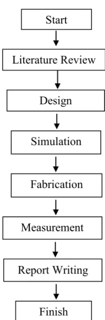
1.1 Project flow chart 5
2.1 Radiation pattern 8
2.2 2.3 2.4 2.5 2.6 2.7 2.8 2.9 2.10 2.11 2.12 2.13 2.14 2.15 2.16 2.17 2.18 2.19 2.20 2.21 2.22
Bandwidth of an antenna
Return loss for 20GHz rectangular patch antenna Directivity of an antenna
Linear polarization Circular polarization
Elliptical polarized EM wave Microstrip Patch Antennas Shape radiating patch Planar antenna
Coplanar antenna Microstrip Line Feed Coaxial Probe Feed Aperture-Coupled Feed Proximity-Coupled Feed Stacked patch
U-slot patch
Segmentation Antenna
Linear Polarized Microstrip Antenna Circular Polarized Microstrip Antenna Circularly Polarized Planar Antenna Circularly Polarized Coplanar Antenna
2.24 2.25 2.26 3.1 3.2 3.3 3.4 3.5 3.6 3.7 3.8 3.9 3.10 3.11 3.12 3.13 3.14 3.15 3.16 3.17 3.18 3.19 3.20 3.21 3.22 4.1 4.2 4.3 4.4 4.5 4.6 4.7
Dual Polarized Planar Antenna Dual Polarized Coplanar Antenna Single Layer X-Polarized Patch Rectangular Patch Antenna
Single Patch Truncated Corners Antenna
Single Patch Truncated Corners Antenna with Slot Type of slots
Slot Arrangement Order
Different Slot Arrangement Order Feeding Technique 1
Feeding Technique 2 Feeding Technique 3
Stacked Patch without Air Gap Stack Patch with Air Gap
Stack Rotated Patch with Air Gap
General Working Window of CST microwave studio Antenna Parameter Setting
Bottom View of Single Patch Antenna Waveguide Port for the Coaxial Probe Waveguide Port for the Feeding Line The flow chart of fabrication process UV Exposure Machine
Etching Machine
The fabricated patch antenna Network Analyzer
Truncated Patch Antenna
Return Loss Graph of Truncated Patch Antenna Axial Ratio Graph of Truncated Patch Antenna Gain and directivity of Truncated Patch Antenna Radiation Pattern of Truncated Patch Antenna Slotted Patch Antenna
Return Loss Graph of Square Slot Antenna
x 4.8 4.9 4.10 4.11 4.12 4.13 4.14 4.15 4.16 4.17 4.18 4.19 4.20 4.21 4.22 4.23 4.24 4.25 4.26 4.27 4.28 4.29 4.30
Axial Ratio Graph of Square Slot Antenna Gain and directivity of Square Slot Antenna Radiation Pattern of Square Slot Antenna Bandwidth versus slot radius
Return Loss Graph of Feeding Technique 1 Axial Ratio Graph of Feeding Technique 1 Return Loss Graph of Feeding Technique 2 Axial Ratio Graph of Feeding Technique 2 Return Loss Graph of Feeding Technique 3 Axial Ratio Graph of Feeding Technique 3
Return Loss Graph of Stacked Patch without Air Gap Stacked Patch Antenna
Return Loss Graph of Stacked Patch Antenna with Air Gap Axial Ratio Graph of Stacked Patch Antenna
Gain and directivity of Stacked Patch Antenna Radiation Pattern of Stacked Patch Antenna Return Loss Graph of Rotated Patch Antenna Axial Ratio Graph of Rotated Patch Antenna Gain and directivity of Rotated Patch Antenna Radiation Pattern of Rotated Patch Antenna Design Process
Final Design
Axial Ratio by Varying Air Gap Distance
LIST OF ABBREVIATIONS
CST - Computer Simulation Technology GPS - global positioning system
ZL - Impedance load
Zo - Characteristic Impedance 50Ω
GHz - GigaHertz MHZ - MegaHertz dB - Decibel mm - Millimeter
Hz - Hertz Km - kilometer
λ - Wavelength
eff
ε - Effective Dielectric Constant
�� - Dielectric constant
CPW - Coplanar waveguide EM - electromagnetic LAN - Local Area Network
MIMO - Multiple Input Multiple Output AR - Axial Ratio
RL - Return Loss
CP - Circular polarization
xii
LIST OF APPENDICES
NO TITLE PAGE
A Graph Axial Ratio versus Radius of Slot 72 B
C
Parametric study varying radius of slotted antenna Parametric study varying position of slotted antenna
74 75 D Parametric study varying air gap distance of rotated
CHAPTER I
INTRODUCTION
This chapter will briefly discuss on the overview of the project. The objective, scope and thesis outline will be presented in this chapter.
1.1 Project Background
Wireless networking has become common needs in the last few years. With prices reduced to a fraction of what they were, it is no wonder that wireless networking products have transitioned from the home, office and currently used in manufacturing. A wireless network provides freedom in convenience and lifestyle to exchange words, data and music or video with any computer across the internet, or around the world. One of the major problems of future mobile communications system is the rapid increase in the demand for different broadband services and applications [1].
2
period of time. This technique can also increase range, or the distance over which data can be transmitted. MIMO approaches show promise of enabling better wireless communications because they mitigate problems inherent in ground-to-ground links, which are the most common links used by wireless devices, including cell phones and Wi-Fi. It is one of several forms of smart antenna technology [2].
Nowadays, there are a lot of methods that can be used to increased antenna bandwidth as well as to generate circular polarization. Circular polarized is defined as a light which consists of two perpendicular electromagnetic plane waves of equal amplitude and difference in phase by 90°. The advantage of circular polarized wave is well known in long distance communication such as satellites communication, radars and global positioning system (GPS). For GPS application, a circularly polarized microstrip antennas is widely been used due to its advantages in receiving signal capability and broad receiving pattern. Other advantage of circular polarized antennas is can reduce the multi-path effect around the receiver. It also has advantage in terms of its attractive physical properties and polarization. Several method of design has been investigated to achieve circular polarization [3, 5].
Furthermore, in order to satisfy the demanded precision and reliability, a high performance antenna must be capable to operate at widen bandwidth. In addition, to meet the required accuracy and reliability, high performance antenna must be able to operate on expanding broadband. Increase the antenna bandwidth will facilitate the high data rate, high mobility, the system roaming and seamless connection by the wireless network. A lot of method has been used to achieve broadband antenna such as slot and stacked method. In general, there are many methods to design a broadband antenna [4].
1.2 Problem statement
time, thus being attractive for broadband multimedia communications. Therefore, along with other developments, widening the bandwidth of polarized antennas has become a major branch of activities in the field of telecommunications.
The use of linear polarization gives a poor performance towards any signals which are not straight and only able to detect the signal in one direction, resulting lost signal strength. Circular polarization (CP) has alleviated this problem by always receive a component of the signal due to the resulting wave having an angular variation. CP antennas is able to send and receive signals in all angles, thus the signal strength is not transferred anywhere but to a different plane and are still utilized. Therefore, the aim of this project is to design a circularly polarized antenna at 2.4 GHz for MIMO applications. The main advantage of using circular polarization is that regardless of receiver orientation, it will always receive a component of the signal [5].
The challenge for RF engineers is to understand the complex systems starting with the transmitter and ending with the receiver. MIMO technique is used to improve channel capacity of the antenna. Not only that, MIMO technique is applied in order to improve the robustness and performance of wireless links. The term multiple-input multiple-output refers to the use of an array of antennas for both transmitting and receiving sides. These requirements such as broad bandwidth, polarization, high gain and smaller physical size of antenna are the criteria that will attract the attention of researchers and engineers to use widely in RF and microwave engineering.
1.3 Objectives
4
1.4 Scope Project
This project will focus on the design of broadband X-circular polarized antenna. The design is divided into three main parts which are design, simulate and fabricate circular polarized antenna, broadband circular polarized antenna and follow by broadband X-circular polarized antenna. The broadband X-circular polarized is designed by using probe feeding methods with several techniques which are calculation and parametric study. Then, the design is simulated by using Computer Simulation Technology (CST) 2010 software to analyze the antenna parameter through 3D techniques. The fabrication process is done by chemical etching technique using multiple layer FR4 board and 50Ω SMA port. Network analyzer and antenna measurement system are used to measure return loss, bandwidth, radiation pattern and gain of the design antenna.
1.5 Project Methodology
Figure 1.1: Project flow chart
1.6 Thesis Outlines
Chapter I will covers on the introduction of the project. A little explanation is discussing related to the project. Specification parameter of the project and the problem statement of the project are also discussed and mention in this chapter. Nevertheless, it also includes the objectives, scope of work and methodology of the project.
Chapter II consists of literature review of the project. The literature review was obtained from references book, journal paper, and technical paper. The literature review includes the review of basic antenna parameter and specification of the design. Basic antenna parameter is discussed and explained with the aid of figure.
Report Writing
Finish Literature Review
Design
Simulation Start
Fabrication
6
In chapter III, project methodology is fully covered with explanation and discussion about the method of design antenna. The method of designing antenna will be include the design process, simulation, and fabrication and followed by antenna measurement. The first until last steps of the design are explained in detail in this chapter. All equation and parameter used are state in detail in this chapter.
The result from the simulation and measurement is analyzed, compared and explained in very detail statement in Chapter IV. The detail finding on analysis results for fabrication and measurement process is presented in this chapter.