DOI: 10.12928/TELKOMNIKA.v11i4.1247 803
Circularly Polarized Proximity-Fed Microstrip Array
Antenna for Micro Satellite
Muhammad Darsono, Endra Wijaya*
Electrical Engineering Department, Faculty of Engineering, Darma Persada University Radin Intan II street (Terusan Casablanca), Phone; +62-021- 8649057 (ext: 2018)
Fax: 021-8649052, Jakarta 13450, Indonesia
*Corresponding author, e-mail: [email protected], [email protected]
Abstrak
Perancangan antena array microstrip dengan sifat polarisasi sirkular dikembangkan guna mendukung teknologi satelit mikro. Antena array polarisasi sirkular ini digunakan untuk pengiriman data yang beroperasi di frekuensi S band dari satelit ke stasiun bumi. Penelitian ini menggunakan rancangan array patch dengan teknik proximity coupling untuk memperoleh gain tinggi dan bandwidth lebar. Struktur antenna array terdiri dari empat elemen patch persegi yang identik sedangkan untuk saluran transmisi menggunakan konsep corporate fed network dengan tiga power divider transformer seperempat lambda- T-junction. Bandwidth impedansi matching untuk resonansi antara dua patch system antena pada
frekuensi tengah 2,25 GHz adalah ¾ . Antena dirancang menggunakan metode momen. Simulasi
dilakukan menggunakan aplikasi microwave office software. Hasil dari simulasi dan pengukuran antena diperoleh adalah: bandwidth dari return loss < -10 dB diatas 100 MHz untuk frekuensi resonansi bergeser 1,75%, VSWR (1 sampai 2) dan bandwidth dari axial rasio < 3 dB adalah 1,6% (narrowband) dan directivity maksimum (Gain) adalah 9,128 dB. Secara keseluruhan hasil studi antena array memperlihatkan kinerja baik dengan sifat polarisasi sirkular, gain tinggi dan beroperasi di daerah frekuensi S band system satelit mikro.
Kata kunci: antena mikrostrip, patch array, polarisasi sirkular, coupling proximity, S band.
Abstract
Design of circular polarization microstrip antenna array was developed to support micro-satellite technology. Circular polarization antenna array used for data transmission applications operating in the S band frequencies from the satellite to the ground station. In this study of the patch array using proximity coupling techniques in this study to obtain high gain and wide of bandwidth. The structure of the antenna array design consists of four identical square patch elements and to use the concept of corporate transmission line fed power divider network uses three transformers quarter-lambda T-junction. Bandwidth impedance matching for resonance between two patches is ¾ antenna system for center frequency of 2.25 GHz. The antenna is designed using the method of moments through simulation with microwave office software applications. The results of simulations and measurements obtained antenna parameters, such as: bandwidth of return loss <-10 dB above 100 MHz resonant frequency shifted to 1.75%, VSWR (1 to 2), the bandwidth of axial ratio <3 dB is 1.6% (narrowband) and the maximum directivity (gain) is 9.128 dB. Overall study results showed good performance antenna array with circular polarization properties, high gain and operates in the S band frequency micro satellite system.
Keywords: microstrip antenna, array patch, circular polarization, proximity coupling, S band.
1. Introduction
The microstrip array patch (1x4) antenna designed and developed to support sub system of micro satellite technology. Antenna array design is the study as a comparison against the helical antenna applications that currently use the micro satellites as show in figure 10 [3]. In this case study, the design of the antenna is made up through the approach of parameter values and characteristics of the antenna as well as the physical dimensions of the body size of a micro satellite. So that the ultimate goal of this study obtained a prototype antenna that has the form of a minimum size of the body wall and optimal performance in the S band frequencies with circular polarization of the micro satellites.
Circularly polarised microstrip array are classified into three major categories .The study of array antenna with use for design use method of arrays which are composed of circularly polarised microstrip patch. For design corporate fed network of transmission line distribution to connecting each patch radiators used power divider transformers of T-junction type [4-5]. For the design of antenna array (1x4) in simulation process conducted with reconstruction model of the typical circularly polarised patches antenna as shown in figure1. For resonance frequencies result of composed linear between spaces of two patches as sub array circularly polarized [6]. The feeding technique of proximity coupled is used in design needed two layers substrate material, where the structure of composed fourth patches identical design in upper layer and the structure of corporate fed network design in bottom layer [7]. In this design of antenna, the sub rate material type using duroid RT 5880 specification has thickness is 1.57mm and dielectric constant of 2.2 [8]. The design of antenna used method of moments by simulation using microwave office software applications. The target of antenna parameter is the bandwidth of return loss below 10 dB, the VSWR (Voltage Standing Wave Ratio) 2:1, bandwidth of axial ratio below 3 dB, and a maximum directivity (gain) of 8 dB [3].
The prototype of antenna array design obtained is show form has the dimensions for the length and width of an area smaller than the size of the satellite body wall. Results of the prototype antenna measurements conducted in the laboratory of electrical engineering department University Indonesia shows the expected results, although there is still a deviation value.
2. Research Method
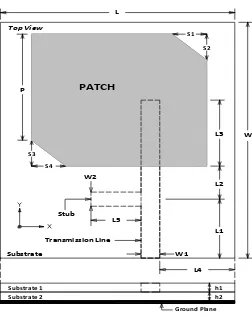
In this study, for design of array antenna (1x4) we used the first method simulation with reconstruction model in experiment on figure1. The second method using sub array design for two patches with proximity –fed single transformer of quarter wave. Figure 1 is typically of right handed circularly polarized (RHCP) microstrip antenna square patch operating in S band frequency of micro satellites [9]. The structure of antenna design with using proximity coupling technique, this design has composed of two layers material substrate by use of duroid same type.
Based on, the length (L) of the square patch antenna design required to work at frequency centre is given by equation (1) [10].
eff c
f c L
2 (1)
Where c is the speed of light (3.108 m / s), r is the dielectric constants and fc is the center
frequency (Hz).
Figure 1. Design of antenna single element
Based on, characteristic impedance (Zo) of transmission line, where Zo for w / h ≥ 1 is given by
For characteristic impedance is 50 Ohm, where εeff is the effective dielectric constant obtained
1.891, so that the transmission line width (w1) is 4.8 mm.
In this study, the array antenna design using proximity coupling technique performed with a two-step design. The first step is to design the structure of the composition of the patch on the upper substrate layer with a linear array method. The second step is to design the structure of a microstrip transmission line using the concept of corporate feed network [5] on the substrate bottom layer. Figure 3 shows the shape of the structure of four identical patch elements separated by a distance of resonance 3/4 lambda for two patch elements. Antenna array has the dimensions for the size of the substrate used is 300 mm x 160 mm.
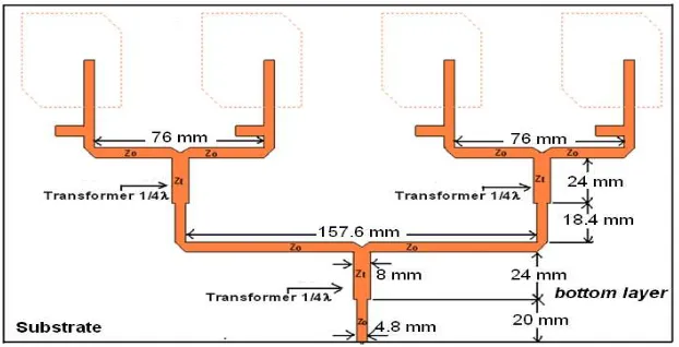
Figure 4 shows the structure of the corporate feed network transmission line on the bottom layer substrate. The feed network circuit element, there are three transformers quarter lambda. The characteristic impedance of 50 for the quarter-lambda state matching transformer to a length of 24 mm. For each quarter lambda transformer impedance in the circuit of the transmission line has an impedance of 35.3 [6]. While the width of the transmission line impedance of the transformer is obtained through the equation 2 is 8 mm.
For resonance obtained optimal distance between the two patches that operate at a frequency of 2.25 GHz is three-quarters of lambda or 80 mm [6]. While lambda guide obtained was 96.7 mm by equation (3). g is the lambda guide of propagation in the microstrip
eff g
0(3)
Where, 0 = c / f, c is the speed of light (3. 10
8
m / s) and f is the operating frequency in Hertz.
Figure 2. Design of array a patch structure
Figure 3. Design of corporate feed network transmission structure.
For impedance transformer is obtained by using equation (4) [5,11,12]:
2 0
Z
Zt (4)
Where, Zt is impedance transformers in Ohm, Z0 is the characteristic impedance of the
microstrip transmission line.
3. Results and Analysis
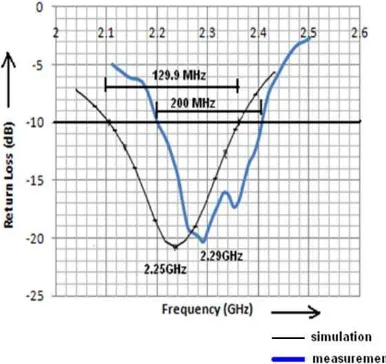
is showed graphic of return loss versus frequency of simulation and measurement. For bandwidth of return loss < -10 dB by obtained is 129.9 MHz (simulation) and 200 MHz (measurement). Center frequency of the minimum return loss obtained shifted from 2.25 to 2.29 GHz. For VSWR < 2 shows the obtained minimum VSWR is 1.19 (simulation) and 1.21 (measurement) as shown in figure 5. The results of simulation and measurement shows the bandwidth parameters obtained in the S band frequencies of micro satellite LAPAN TUBSAT.
Figure 6a shows the simulated matching impedance bandwidth of input impedance of the antenna at frequency 2.25 GHz is 0.89264 - j0.130427, or about 44.81015 - j 7.09925. The measurement results of the input impedance at frequency 2.28 GHz is 55.736 + j 7.2269 as shown in Figure 6b. This value indicates that both simulated and measured input impedance of the antenna are nearly the same as the characteristic impedance of 50 transmission line. Therefore matching conditions are occurred.
Figure 4. Return loss vs. frequency Figure 5. VSWR vs. frequency
Figure 6a. Input impedance of Figure 6b. Input impedance of simulation results masurement results
Figure 6. Input impedance results
Figure 7. Axial ratio vs. frequency Figure 8. Polarization radiation of simulation of simulation results
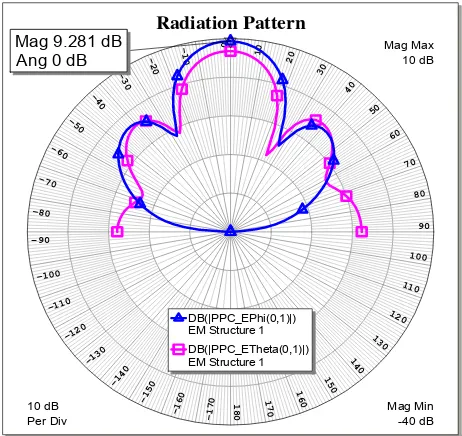
Figure 9. Radiation pattern of simulation results
Figure 7 is showed the axial ratio versus the frequency of simulation results. The target of axial ratio bandwidth of circular polarization is less than 3 dB. The bandwidth obtained (2.2353 to 2.2726 GHz) of axial ratio less than 3 dB is 37.3 MHz or 1.6% (narrowband). The axial ratio minimum obtained is 0.6426 dB at frequency 2.25 GHz. Achieving good performance to limit the size of circular polarization characteristics of the system bandwidth.
Figure 8 is showed the E field of polarization radiation of simulation results. Polarization obtained show that there are two types of polarization RHCP and left handed circularly polarized (LHCP). To obtain maximum power RHCP radiation is 9.185 dB (00 angle precisely), the Half Power Beamwidth (HPBW) of total power radiation is 36.20 from -18.40 to 17.8º. Figure 9 is showed of power radiation pattern of directivity simulation results. The directivity maximum of radiation pattern obtained of gain parameter of E-phi to E-Theta is 9.281dB. The target parameters are expected to gain antenna characteristics on micro satellite.
The overall results of the experimental design for parameter array antenna in accordance with expectations. In this case, a good antenna array performance based on the results of the simulations and validation through measurements in the laboratory. A prototype is
obtained from the antenna array design has a simple design structure for circular polarization characteristics as shown in Figure 11. In the manufacture of fabricated antenna using proximity coupling technique difficulty in combining the substrate layer of the patch structure with the substrate bottom layer transmission line structure. So that there is no gap between the layers necessary mounting screws on the plastic substrate plane without passing patches lines or transmission lines. Prototype antenna has dimensions of the substrate to a length of 30 cm and width of16 cm. Part of the layers below the edge of the end of the input transmission lineplaced a coax-connector SMA. In the dimension size of the antenna can still be placed on the side of the plane of the satellite, where the size of the field of satellite body is 45 cm x 27 cm.
The specifics of the performance of antenna array based on simulation and measurement results shown in table 1. The performance of antenna visible for wide of bandwidth shift of 35.05% and the resonance frequency shift of 1.75% to measurement results. So it is with minimum VSWR and of input impedance experience shift to measurement result.In simulation, axial ratio bandwidth obtained narrowband characteristic and the polarization characteristics obtained dual circular polarization. So that is minimum beam width of power radiation pattern to previous experiment result.
Figure 10.LAPAN TUBSAT micro satellite Figure11. Prototype of antenna array design upper shelf [3]
Table 1. Parameters of Simulation and Measurement Antenna Array Results
Parameter Simulation Measurement
Bandwidth 129.9 MHz 200 MHz
Resonance frequency 2.25 GHz 2.29 GHz
Minimum VSWR 1.19 (2:1) 1.21(2:1)
Matching Impedance (Zin) 44.81015 - j 7.09925 55.736 + j 7.2269 Axial ratio bandwidth 37.3 MHz (< 3 dB ) -
Beam width 36.2 Degree -
Gain (Max. Directivity ) 9.281 dB -
Polarization RHCP-LHCP -
Impedance 50 -
4. Conclusion
when the maximum directivity (gain) of the radiation pattern of the antenna array. Although a deviation in the value parameter simulation and measurement results in table 1, but still shows the performance of the antenna in accordance with the target on LAPAN TUBSAT micro satellite system. Achievements of the size dimensions of the antenna design results still meet the target, when the prototype was placed on the satellite body.
References
[1] Rakhim Yuba. Development of Micro Satellite Indonesia (in Indonesia). Online Journal of Space Communication. Issue8: Regional Development: Indonesia. Fall.2004.
[2] W Hasbi, E Nasser, A Rahman. Spacecraft Control Center of Lapan-Tubsat Micro Satellite. National Institute for Aeronautics and Space (LAPAN)-Indonesia.
[3] Triharjanto, H. R, et al. LAPAN-TUBSAT. Micro-Satellite Platform for Surveillance & Remote Sensing. 4S Symp. La Rochelle, 2004. http://www.esa.int/esapub/conference/toc/tocSP571.pdf
[4] JR James & PS Hall. Handbook of Microstrip Antennas. In: K Ito, T Teshirogi, S Nishimura. Circularly polarised antenna arrays. Peter Peregrinus Ltd. London. 1989; 1: 756-810
[5] JR James, PS Hall. Handbook of Microstrip Antennas. In: RP Owens. Microstrip antenna feeds. Peter Peregrinus Ltd. London. 1989. 1: 850-854.
[6] M Darsono. Design of Microstrip Antenna Array (1x2) Square patch Circular Polarization in S band Micro Satellite (in Indonesia). Proceeding of SMAP. University Indonesia. Depok. 2012: 27-30. [7] Yohandri, J T Sri Sumantyo, H Kuze. Circularly Polarized Array Antennas for Synthetic Aperture
Radar. PIERS Online. 2011; 7(6): 583-586.
[8] High Frequency Laminate: Standard Thickness, Tolerances and Panel Sizes. www.rogerscorporation.com
[9] M Darsono. Design of Microstrip Antenna Circular Polarization using Coupling Proximity Feeding Technique (in Indonesia). Proceeding of SIPTEKGAN XV. LAPAN. Banten. 2011: 553-559.
[10] Wong KL. Compact and Broadband Microstrip Antennas. New York: John Willey & Son, 2002. [11] Robert E. Collin. Foundation for microwave engineering. McGraw-Hill, 2nd ed. 1992.