DOI: 10.12928/TELKOMNIKA.v14i4.4137 1338
Enhanced Antenna Design for Rectenna Application in
the 2.45 GHz ISM Band
Sharif Ahmed, Zahriladha Zakaria*, Mohd Nor Husain, Azahari Salleh, Ammar Alhegazi Centre of Telecommunication Research and Innovation (CeTRI),
Faculty of Electronic and Computer Engineering (FKEKK), Universiti Teknikal Malaysia Melaka (UTeM), Hang Tuah Jaya 76100, Melaka, Malaysia
*Corresponding author, e-mail: [email protected]
Abstract
In this paper a two layers microstrip antenna design at 2.45 GHz ISM band with Harmonic rejection filter embedded on the ground plane is presented. The two roger substrates with relative permittivity of 2.2 are separated by an air gap which enhances the antenna gain. The design is simulated using Computer Simulation Technology (CST) Studio Suite 2015. Different aperture couplings slots such as rectangular and triangular aperture coupling slots are studied and compared. It is found that the antenna with triangular aperture coupling slot enhances the antenna performance by suppressing 2nd and 3rd harmonics at 5 GHz and 8 GHz, respectively, increasing the antenna gain and providing a better circular polarization behavior. The simulated antenna design achieves a gain of 9 dB, return loss of -23.6dB, axial ratio of 1.27dB and axial-ratio bandwidth of 40.8% (2 ~ 3 GHz). The proposed antenna shows an enhancement in the antenna performance which makes it a suitable candidate for rectifying antenna or rectenna application as it can increase the total conversion efficiency resulting in a high output DC voltage used to power low power electronic and electrical devices such as wireless sensor.
Keywords: Antenna, Aperture coupling, Harmonic rejection, circular polarization, Rectenna application
Copyright © 2016 Universitas Ahmad Dahlan. All rights reserved.
1. Introduction
Rectenna is a device used to capture ambient electromagnetic signals and convert them into a DC voltage to power low power devices such as wireless sensor. It consists of an antenna, harmonic suppression filter, rectifying circuit and resistive load [1, 2]. The most important parameters in rectenna design are the total conversion efficiency, associated cost and the physical size. There have been many efforts on improving the rectenna design by increasing its conversion efficiency as the efficiency reduction is due to the nonlinear behavior of the diodes that cause generation of unwanted harmonic of the fundamental frequency. To overcome this issue, many researchers have proposed adding a low pass filter between the antenna and the rectifying circuit [3-9] to suppress unwanted harmonics so that the rectenna efficiency would be increased. However, the adaption of the Low Pass Filter (LPF) increases the size and cost of the rectenna and cause isolation loss which limit the practical implementations of the rectenna.
In [10], the harmonic rejection property is added to the antenna by embedding unbalanced slots structure so the isolation loss associated with the LPF is eliminated. Antenna with triangular shape can suppress generated harmonics by nonlinear diodes as presented in [11]. In [12] a technique of four right-angle slits applied to the patch antenna design can block second and third harmonic signals. In prior literature [10-15], the antenna designs can reject the unwanted harmonics with no need for the harmonic rejection Filter (HRF). However, most of these designs suffer from low gain which degrades the overall rectennna conversion efficiency.
In this paper, a two layers high gain high order harmonic rejection circularly polarized antenna design is proposed. The gain of the antenna is enhanced by using an air gap between two layer substrates. This antenna design uses different aperture coupling slots etch on the ground plane to suppress unwanted harmonics. Harmonic rejection filter is replaced by an internal filter within the antenna which reduces the size.
2. Antenna Design Procedures
The proposed stacked microstrip antenna is shown in Figure 1(a). A square patch is etched on the top layer as shown in Figure 1(b). A single feed line of 50Ω impedance is designed on the bottom layer as shown in Ffigure 1(c). The aperture coupling slots such as right angle triangular and rectangular coupling slots are designed with 45° rotation angle, to achieve the circular polarization property, on the second layer as shown in figure 1(d) and figure 1(e), respectively. The two layer substrates are separated by spacer or plastic holder of 5 mm which enhances the antenna gain.
The design uses Roger 5880 substrate with relative permittivity of 2.2, 0.0009 tangent loss, and 0.035mm copper thickness. Equations are applied to obtain the proposed antenna dimension [22, 23] as following:
The width of the square patch can be obtained using equation (1):
�� = ��√��+ (1)
The effective length, � is calculated using equation (2)
The patch actual length, Lp is calculated using equation (4).
Figure 1. Geometry of the proposed stacked antenna with the dimensions of Wp = Lp= 46mm, Ls= Ws = 100mm, g=5mm, h1 = h2 = 0.787mm, Lf = 50mm, wf = 2.342mm, R1 = 27.25mm, R2
= 14mm, T = 25.45mm, T1 = 18mm. (a) Antenna side view, (b) Top view of the square patch, (c) bottom view of the feedline (d) Second layer with right angle triangle slot view (d) Second
layer with rectangular slot view
3. Results and Discussions
In this section, the antenna parameters such as return loss and harmonic rejection property, bandwidth, gain, and axial ratio are discussed and analyzed.
3.1. Return Loss and Harmonic Rejection Property
3.1.1. Return Loss of the Antenna with Rectangular and Triangular Aperture Coupling Structure
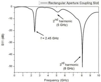
The simulation is carried over a range of 0-10 GHz. The resonance frequency of 2.45 GHz of the antenna with rectangular aperture coupling slot can achieve return loss of less than -15dB. However, harmonics are generated at 5 GHz and 8 GHz, as shown in Figure 2, which reduces the antenna efficiency. The antenna with right angle triangular aperture coupling slot achieves less than -23dB return loss at 2.45 GHz resonance frequency with no harmonics generated, as shown in Figure 3.
Figure 2. Antenna return loss with the rectangular aperture aperture coupling slot
Figure 3. Antenna return loss with the triangular aperture coupling slot
3.1.2. Harmonic Rejection Comparison of Rectangular and Triangular Aperture Coupling Slots
(c) Lf Wf
(e) R1
R2
(d) T
T1
Spacer h1
h2 Air Gap (g)
(a) Square Patch
(b) Wp
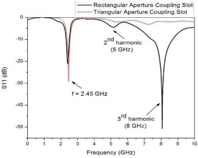
The antenna with rectangular aperture coupling slot generates 2nd and 3rd harmonics at 5 GHz and 8 GHz respectively. However, the antenna with triangular aperture coupling slot rejects theses harmonics resulting in very low return loss of -23.68dB at the fundamental frequency compared to that obtained with the antenna with rectangular aperture coupling slot, as shown in Figure 4. The antenna with triangular aperture coupling slot is able to reject high order harmonics due to the reflection of second and third harmonics noises when feeding into the slot as they fail to create a current resonance around the slot so the power radiated at 2nd and 3rd harmonics is reduced, whereas the power radiated at the 1st harmonic or at the fundamental frequency is increased which improves the overall antenna efficiency at 2.45 GHz.
Figure 4. Return loss comparison of the rectangular and triangular aperture coupling slots
Table 1. Return Loss of Comparison
Aperture slot Fundamental frequency (2.45 GHz)
2nd harmonic (5 GHz)
3rd harmonic
(8GHz)
Rectangular slot -15.4dB -4.22dB -26.4dB
Triangular slot -23.6dB -1.4dB -1.74dB
3.2. Antenna Gain
The antenna with rectangular aperture coupling slot can achieve a realized gain of 8.852dB and total efficiency of -0.1908, whereas the antenna with triangular aperture coupling slot can achieve up to 9.01 dB with total efficiency of -0.0187 as shown is Figure 5(a) and Figure 5(b), respectively. It is observed that the use of triangular aperture coupling slot has enhanced the gain as well as the efficiency of the antenna which is due to strong coupling achieved with triangular aperture coupling slot.
From the antenna gain direction, it is noted that the main beam direction is 180 degree which means the main radiation is from the loaded slot toward the antenna patch direction. The antenna main radiation is to the front of the antenna patch which makes it suitable for receiving the wave signals in rectenna application.
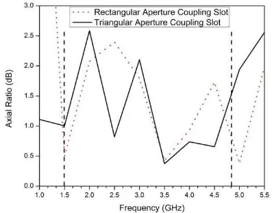
3.3. Antenna Axial Ratio
polarization behavior as the axial ratio is closed to the ideal case where the two electric fields components are equal in magnitude and orthogonal to each other (out of phase by 90°).
(a) (b)
Figure 5. Antenna gain (a) Gain of the antenna with rectangular aperture coupling slot (b) Gain of the antenna with triangular aperture coupling slot
In the proposed antenna design, the air gap is introduced as it has very significant effect on the antenna gain. By varying the air gap height, the antenna gain varies as well. Parametric study is carried on the air gap value, g, as shown in Figure 7, from 0 mm to 10 mm. it is observed that the antenna gain increases dramatically to 9.01dB at 5 mm air gap. However, the antenna gain drops at air gap higher than 5 mm. The air gap height is optimized to achieve high gain with reasonable antenna size. The air gap is set to 5mm to maintain small size of the antenna design with a high gain.
Figure 6. Axial ratio of antennas with rectangular and triangular aperture coupling
slots
Figure 7. Study of the air gap effect on the antenna gain
3.4. Results Comparison
at 2.45 GHz eliminates the harmonics generation at higher frequencies, at 5 GHz and 8 GHz, which increased the radiated power at the fundamental frequency resulting in a high performance of the antenna. This antenna can be used in rectenna application as it can achieve high performance required for such application.
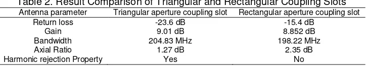
Table 2. Result Comparison of Triangular and Rectangular Coupling Slots
Antenna parameter Triangular aperture coupling slot Rectangular aperture coupling slot
Return loss -23.6 dB -15.4 dB
In this paper, a two layer microstrip antenna design at 2.45 GHz with different aperture coupling slots such as rectangular and triangular aperture coupling slots has been presented. From comparison carried, it is found that antenna with triangular aperture coupling slot can suppress 2nd and 3rd harmonics at 5 GHz and 8 GHz, respectively. Besides that, this antenna can achieve 9 dB gain, -23.68 dB return loss, 204.83 MHz bandwidth, 1.27dB axial ratio (AR) and axial-ratio bandwidth of 40.8% (2 ~ 3 GHz). Based on results evaluation of different antenna parameters, this antenna can be well-suited for the rectenna application so that rectenna would have high efficiency, low cost and small size. In future, the fabrication process of the proposed antenna can to be carried out.
Acknowledgements
We are grateful to Centre for Telecommunication Research and Innovation (CeTRI), Faculty of Electronic &Computer Engineering (FKEKK) and Universiti Teknikal Malaysia Melaka (UTeM) for their encouragement and help to complete this research work. Authors also would like to thank Centre for Research and Innovation Management (CRIM) and UTeM Zamalah Scheme for the financial support.
References
[1] WC Brown. The history of power transmission by radio waves. IEEE Trans. Microw. Theory Tech. 1984;
32(9):1230-1242.
[2] Hong SSB, Ibrahim RB, Khir MHM, Zakariya MAB, Daud H. WI-FI energy harvester for low power RFID
application. Progress In Electromagnetics Research C. 2013; 40: 69-81.
[3] M Han, S Jung, H Sohn. High Efficient Rectenna Using a Harmonic Rejection Low Pass Filter for RF
based Wireless Power Transmission. International Symposium on Wireless Communications Systems (ISWCS). 2014: 423-426.
[4] A Mavaddat, S Armaki, A Erfanin. Millimeter-wave energy harvesting using 4 × 4 microstrip patch
antenna array. IEEE Antennas Wireless Propag. Lett. 2015; 14: 515-518.
[5] XX Yang, C Jiang, A Elsherbeni, F Yang, YQ Wang. A novel compact printed rectenna for data
communication systems. IEEE Trans. Antennas Propag. 2013; 61(5): 2532-2539.
[6] J Zhang, ZP Wu, CG Liu, BH Zhang, B Zhang. A Double-sided Rectenna Design for RF Energy
Harvesting.International Wireless Symposium (IWS). 2015; 56(3): 882-886.
[7] H Takhedmit, L Cirio, B Merabet, B Allard, F Costa, C Vollaire, O Picon. Efficient 2.45GHz rectenna
design including harmonic rejecting rectifier device.Electron. Lett. 2010; 46: 811-812.
[8] Kim P, G Chaudhary, Y Jeong. A dual-band RF energy harvesting using frequency limited dual-band
impedance matching. Progress In Electromagnetics Research. 2013; 141: 443-461.
[9] JH Chou, DB Lin, KL Weng, HJ Li. Novel T-shape slot couple feed dual circular polarized rectenna. In
Proc. Int. Symp. Antennas Propog. Nagoya, Japan. 2012: 178-181.
[10] TC Yo, CM Lee, CM Hsu, CH Luo. Compact circularly polarized rectenna with
unbalanced circular slots. IEEE Trans. Antennas Propag. 2008; 56(3): 882-886.
[11] MS Bin-Melha, RA Abd-Alhameed, CH See, M Usman, ITE Elfergani, JM
Noras. Harmonic rejection triangle patch antenna. PIERS Proc. 2012: 1514-1517.
[12] FJ Huang, TC Yo, CM Lee, CH Luo. Design of circular polarization antenna
with harmonic suppression for rectenna application. IEEE Antennas Wireless Propag.
[13] Gao YY, XX Yang, C Jiang, JY Zhou. A circularly polarized rectenna with low
profile for wireless power transmission. Progress in Electromagnetics Research Letters.
2010; 13: 41-49.
[14] ZK Ma, GAE Vandenbosch. Wideband harmonic rejection filtenna for wireless
power transfer. IEEE Trans. Antennas Propag. 2013; 62(1): 371-377.
[15] N Zainol, Z Zakaria, M Abu, MM Yunus. Harmonic Suppression Rectangular Patch
Antenna with Circularly Polarized. TELKOMNIKA Telecommunication Computing
Electronics and Control. 2016; 14(2): 471-477.
[16] Chou JH, Lin DB, Weng KL, Li HJ. All Polarization Receiving Rectenna With
Harmonic Rejection Property for Wireless Power Transmission. IEEE Trans. Antennas
Propag. 2014; 62(10): 5242-5249.
[17] Haboubi WH, Takhedmit JD, Lan Sun Luk, SE Adami, B Allard, F Costa, C
Vollaire, O Picon, L Cirio. An efficient dual-circularly polarized rectenna for RF
energy harvesting in the 2.45GHz ISM band. Progress in Electromagnetics Research. 2014;
148; 31-39.
[18] Lai XZ, ZM Xie, XL Cen. Design of dual circularly polarized antenna with high
isolation for RFID application. Progress In Electromagnetics Research. 2013; 139: 25-39.
[19] M Darsono, E Wijaya. Cirlularly Polarized Proximity-Fed Microstrip Array Antenna for
LAPAN TUBSAT Micro Satellite System. TELKOMNIKA Telecommunication Computing Electronics
and Control. 2013; 11(4): 803-810.
[20] KL Chung. A wideband circularly polarized H-shaped patch antenna. IEEE Trans.
Antennas Propag. 2010; 58(10): 3379-3383.
[21] LX Bao, MJ Ammann, P McEvoy. Microstrip-fed wideband circularly polarized
printed antenna. IEEE Trans. Antennas Propag. 2010; 58(10): 3150-3156.
[22] CA Balanis. Antenna Theory Analysis and Design. 2nd edition. John Wiley and Sons (Asia). 2005.
[23] DM Pozar, SD Targonski. Improved coupling for aperture-coupled microstrip antennas. Electron. Lett.