A Meandered Triple-band Printed Dipole Antenna for RFID
Maisarah Abu1, Mohamad Kamal A. Rahim1, M. K. Suaidi2, I. M. Ibrahim2and N.M. Nor2 1
Radio Communication Engineering Department, Faculty of Electrical Engineering, Universiti Teknologi Malaysia (UTM),
81310 Skudai, Johor Bahru, Malaysia. 2
Telecommunication Engineering Department, Faculty of Electronic and Computer Engineering, Universiti Teknikal Malaysia Melaka (UTeM),
Karung Berkunci No. 1752, Pejabat Pos Durian Tunggal, 76109, Durian Tunggal, Melaka, Malaysia. [email protected], [email protected], [email protected], [email protected],
Abstract — In this paper, a meandered triple-band printed
dipole antenna is proposed for Radio Frequency Identification (RFID). This meandered tri-band printed dipole antenna is designed to operate at 0.92 GHz, 2.45 GHz and 5.8 GHz with the aid of Computer Simulation Technology (CST) software. In order to achieve triple-band operation, the proposed antenna contains two branch elements, which act as an additional resonator. The designed antenna is fabricated using Taconic
RF-35 substrate with a dielectric constant (Hr) of 3.5 and
thickness (h) of 0.508 mm. The antenna’s parameters for
triple-band operation are investigated and discussed. Then, this fabricated antenna is integrated with the UHF microchip to become a passive UHF tag. This tag is tested by measuring the reading distance and it is found that the proposed tag can be used for RFID application.
Index Terms — triple-band, dipole antenna, meandered,
RFID, UHF tag.
I. INTRODUCTION
Passive Ultra High Frequency (UHF) Radio Frequency Identification (RFID) technology has become increasingly popular in various areas of automatic identification of objects such as access control, animal tracking, inventory management, asset identification and manufacturing industry. Basic passive UHF and Microwave Frequencies RFID systems consist of a passive tag or transponder with stored information that is attached to an object and a reader that transmits commands and energy to activate the tag using electromagnetic wave [1-2]. The communication from tag to reader is based on electromagnetic wave backscattering modulation by the data stored on tag. Generally, a RFID tag consists of an Application Specific Integrated Circuit (ASIC) microchip connected to an antenna.
Printed dipole antenna have been actively studied since they are simple, easy to fabricate, and easy to integrate with the ASIC microchip. In recent years, several triple-band printed dipole antennas were reported. A triple-band printed dipole antenna using parasitic elements was proposed in [3]. The proposed antenna contains two parasitic elements as additional resonators by coupling from the driving dipole antenna. The antenna was designed and analyzed at the bands of PCS (Personal Communication Service: 1750 ~ 1870
MHz), IMT-2000 (International Mobile Telecommunication-2000: 1920 ~ 2170 MHz), and ISM (Industrial Scientific and Medical: 2400 ~ 2483.5 MHz). In [4], a triple-band omni-directional antenna which comprises three pairs of dipoles placed back to back and printed on a dielectric substrate was presented for WLAN applications (2.4 GHz, 5.2 GHz and 5.8 GHz).
In this paper, a meandered triple-band printed dipole antenna is constructed based on a printed triple-band monopole antenna that was proposed in [5]. Then, the developed antenna is integrated with the 902-928 MHz ASIC microchip to become a passive UHF tag. In order to validate the performance of the fabricated tag, the measuring distance of the tag is recorded. Thus, a passive UHF reader is required for this purpose.
II. ANTENNA DESIGN
The meandered triple-band dipole is printed on one side of Taconic substrate (dielectric constant, Hr = 3.5, thickness,h =
0.508 mm and tangent loss,G = 0.0019) with a substrate size of 105 mm x 20 mm. In order to achieve a triple-band
operation,the prime dipole antenna is connected to the two
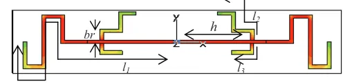
branch elements (l2 and l3), which act as an additional resonator to resonate at 2.45 GHz and 5.8 GHz. The length of the prime dipole, l1is meandered to reduce the antenna size. The structure of the designed antenna is shown in Fig. 1. A 2.0 mm gap at the centre of the antenna is connected by a discrete port of 50:. Fig. 1 also shows the surface current at
0.92 GHz.
l2
Fig. 1. The structure of the designed triple-band printed dipole antenna and surface current at 0.92 GHz.
The effects of the parameters on the frequency shift and the input impedance are also investigated. It is found that the length of theprime dipole and length of the branch elements
l1 l3
h br
give significant effect on resonant frequency or input impedance of the antenna.
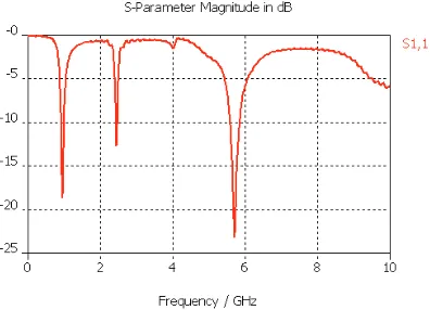
Fig. 2 and 3 shows the graph of optimized simulated return loss and input impedance of the antenna for l1 = 77.3 mm, l2
= 18.1 mm and l3= 10.6 mm, br = 3.5mm and h = 23.0 mm
respectively. Referring to Fig. 2, there are three resonant frequencies. They are 0.92 GHz with return loss of -8.8 dB, 2.45 GHz with return loss of 11.5 dB and followed by 5.8 GHz with return loss of -13.7 dB. The simulated input impedances of these three frequencies are 34.1:, 30.4: and
51.7: respectively.
Fig. 2. The simulated return loss of meandered triple-band printed dipole antenna.
Fig. 3. The simulated input impedance of meandered triple-band printed dipole antenna.
The parameter that only affects the highest resonant frequency is the distance between port and the branch
elements (h). Fig. 4 shows the simulated return loss with
different values of h.
Fig. 4. The simulated return loss with different values of h.
But in Fig. 5, it shows that the three resonant frequencies are generally remain constant. It only shows that the value of input return loss at the highest frequencies is deeper when the length of the branch (br) is decreased from 4.5 mm to 3.5 mm.
Fig. 5. The simulated return loss with different values of br.
III.COMPARISON BETWEEN SIMULATION AND MEASUREMENT RESULTS
The measurement of return loss is done using Agilent 8720ES S-parameter network analyzer (50 MHz – 20 GHz). From the results obtained, it indicates that the proposed antenna provides triple operating frequencies of 920 MHz (900 - 1020 MHz), 2450 MHz (2380 - 2480 MHz), and 5800 MHz (5750 - 6150 MHz) for VSWR<2.6. The measured results are quite similar to those of the simulated results. The slightly different readings are obtained from the simulation due to the fabrication and measurement error.
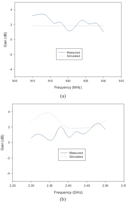
Table 1 tabulates the simulated and measured results of meandered triple-band printed dipole antenna in term of input return loss, bandwidth and gain. The measured bandwidth is recorded for VSWR<2.6 and the developed antenna is considered a narrowband antenna. From this table, it shows that the different reading between the simulated and measured gain of the antenna is 0.6dB, 0.4dB and 2.2dB at 0.92 GHz, 2.45 GHz and 5.8 GHz respectively.
TABLE I
SIMULATED AND MEASURED RESULTS OF MEANDERED TRIPLE -BAND PRINTED DIPOLE ANTENNA
Frequency (GHz)
0.92 2.45 5.8
Sim Mea Sim Mea Sim Mea
Return Loss (dB)
Graph of measured and simulated gain versus frequency for meandered triple-band printed dipole antenna is plotted in Fig. 6.
Frequency (MHz)
905 910 915 920 925 930 935
Gai
2.25 2.30 2.35 2.40 2.45 2.50 2.55
Gain (dB)
5.65 5.70 5.75 5.80 5.85 5.90 5.95
Gain (
Fig. 6. Simulated and measured gain of meandered triple-band printed dipole antenna.
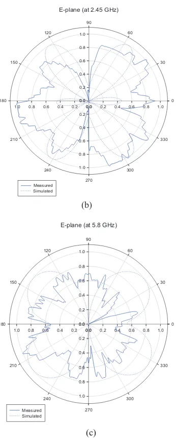
The radiation pattern of the fabricated antenna is measured in anechoic chamber. The measured E-plane radiation pattern at 0.92 GHz, 2.45 GHz and 5.8 GHz is presented in Fig. 7. The patterns exhibit omni-directional pattern at 0.92 GHz. Circular radiation patterns are observed for H-plane for this triple-band antenna.
E-plane (at 0.92 GHz)
E-plane (at 2.45 GHz)
Fig. 8. Fabricated passive UHF meandered triple-band printed dipole tag antenna.
V. CONCLUSION
A meandered printed triple-band dipole antenna resonated at 0.92 GHz, 2.45 GHz and 5.8 GHz has been presented in this paper. The performance of the antenna is investigated and analyzed. With this antenna, it will become a passive triple-band dipole tag when it is integrated with the ASIC microchip. The tested reading distance shows that the passive tag can be used for UHF system.
(b)
E-plane (at 5.8 GHz)
0.0 0.2 0.4 0.6 0.8 1.0
VI. FUTURE WORK
For future work, this triple-band printed dipole antenna will be integrated with the 2.45 GHz and 5.8 GHz microchip. So that, it can be used for passive Microwave Frequencies RFID system. The reading distance of this passive tag then must be recorded to verify its performance.
REFERENCES
[1] Harvey Lehpamer, “RFID Design Principles”, Artech House, 2008.
[2] Zhi Ning Chen, “Antenna for Portable Devices”, John Wiley & Sons, pp. 71-72, 2007.
[3] Kihun Chang, Hyungrak Kim, Kwang Sun Hwang, Ick Jae Yoon, and Young Joong Yoon, “A triple-band printed dipole antenna using parasitic elements”, Microwave and Optical Technology Letters,vol. 47, pp. 221-223, 2005.
(c) [4] Y.-J. Wu, B.-H. Sun, J.-F. Li, and Q.-Z. Liu, “Triple-band
omni-directional antenna for WLAN application”, Progress In Electromagnetics Research, PIER 76, pp. 477–484, 2007. Fig. 7. The simulated and measured radiation pattern of
meandered triple-band printed dipole antenna.
[5] M. John and M. J. Ammann, “Integrated antenna for multiband multi-national wireless combined with GSM1800/ PCS1900/IMT2000+Extension”, Microwave and Optical Technology Letters, vol. 48, No. 3, pp. 613-615, March 2006. IV. MEASUREMENT ON MEANDERED TRIPLE-BAND PRINTED
DIPOLE TAG ANTENNA
Then, the fabricated antenna is integrated with the ASIC microchip (902-928 MHz) to become a passive UHF tag. The developed passive UHF meandered triple-band printed dipole tag antenna is shown in Fig. 8. So, the port at the middle of the antenna is replaced by the microchip. It is required to connect the chip to the radiating element by soldering it carefully. Then, the performance of the tag is tested by measuring the reading distance. Thus, the measured reading distance of 2.5m is recorded by using UHF Gen2 SDK Module. Hence, it indicates that the developed tag can be used for UHF RFID system.