accredited by DGHE (DIKTI), Decree No: 51/Dikti/Kep/2010 417
Development of Wireless Smart Sensor for Structure
and Machine Monitoring
Achmad Widodo, Latief Rozaqi, Ismoyo Haryanto, Djoeli Satrijo Department of Mechanical Engineering, Diponegoro University Jl. Prof. Soedarto SH, Tembalang Semarang 50275, Telp: +62-24-7460059
e-mail: [email protected]
Abstrak
Monitoring berbasis getaran adalah sebuah metode yand dapat dipergunakan untuk menentukan kondisi suatu sistem. Kondisi suatu sistem mekanikal atau suatu sistem struktural dapat ditentukan dari getarannya. Getaran yang dihasilkan oleh suatu sistem dapat menunjukkan kondisi sistem tersebut dan dapat digunakan untuk menghitung lifetime sistem tersebut serta dapat menjadi dasar diambilnya suatu tindakan tertentu sebelum munculnya kegagalan sistem yang fatal. Paper ini menjelaskan bagaimana sensor cerdas nirkabel dapat digunakan untuk mengidentifikasi kondisi suatu sistem dengan memonitor parameter getarannya. Sensor cerdas nirkabel tersebut secara terus-menerus mengukur parameter getaran dari sistem dalam sistem real-time dan mengirimkan data tersebut secara nirkabel menuju suatu host PC yang digunakan untuk proses pengolahan sinyal secara digital, dari proses ini getaran akan diplot dalam bentuk grafik yang digunakan untuk menganalisis kondisi dari sistem. Pada bagian akhir dilakukan beberapa pengujian pada sistem real untuk memastikan akurasi dari sensor cerdas yang digunakan serta metode monitoring yang digunakan.
Kata kunci: getaran, monitoring kondisi, sensor cerdas nirkabel
Abstract
Vibration based condition monitoring is a method used for determining the condition of a system. The condition of mechanical or a structural system can be determined from the vibration. The vibration that is produced by the system indicates the condition of a system and possibly used to calculate the lifetime of a system or even used to take early action before fatal failure occurred. This paper explains how the wireless smart sensor can be used to identify the health condition of a system by monitoring the vibration parameters. The wireless smart sensor would continuously senses the vibration parameters of the system in a real-time systems and then data will be transmitted wirelessly to a base station which is a host PC used for digital signal processing, from there the vibration will be plotted as a graph which used to analyzed the condition of the system. Finally, several tested performed to the real system to verify the accuracy of a smart sensor and the method of condition based monitoring.
Keywords: vibration, condition monitoring, wireless smart sensor
1. Introduction
Condition based maintenance (CBM) currently has been widely used to become a maintenance methods because of high efficiencies. It allows the user to determine the internal condition of the system without stopping the operation of the system [1]. One way to determine the internal or external condition of the system which is running is to monitoring and analyzing the vibration occurred at the system. System information can be extracted from other parameters such as electrical, vibrational, thermal, environmental, oil analysis, etc. [2]. Generally, vibration can be measured by several kinds of sensors such as strain gauge, fiber optic, piezoelectric, laser vibrometer, and accelerometer. Sensor is a device that converts physical parameter, in this case vibration occurred at the system, into a signal (usually electrical signal) which can be read by data acquisition system and then could be processed and analyzed.
ISSN: 1693-6930 418
dynamic acceleration resulted from vibration of machine or strucutre [4]. ADXL345 is a sensor that is manufactured by micromachining technology with a polysilicon structure built on top of silicon wafer. Deflection of the structure inside MEMS accelerometer is measured using differential capacitor that consists of independent fixed plates and plates attached to the moving mass. Acceleration deflects the beam and gives unbalance effect to the differential capacitor, resulting sensor output whose amplitude is proportional with the acceleration. Moreover, wireless smart sensor is equipped with a microprocessor as a controller for the data acquisition and data transmission from wireless smart sensor to the base station. Data transmission from smart sensor to the base station is done wirelessly, this is because of several advantages of wireless data transmission over wired transmission, the used of wired transmission will produce more investation/cost for the installation and maintenance [5-6].
The advantages of the wireless smart sensor compared with the conventional accelerometer are low cost, flexible and software programmable. Moreover, wireless smart sensor can be made into several integrated smart sensor and built a networks called wireless sensor networks (WSN) so the condition monitoring on the system not only be done in single point, but can be done in many nodes so the parameter measurements on the system will be more accurate [7].
2. Platform of the System
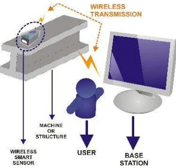
The working principle of smart sensor is shown in the Figure 1, the attached smart sensor on the structure or machine measures the vibration occurred on the system and transmitted to the base station according to the setting on the base station. Communication between smart sensor and base station conducted on two ways half duplex or full duplex through wireless 2.4GHz with the communication module produced by maxtream XBee-Pro that theoretically could transmit data 1.5 km outdoor line of sight. For more details, this infomation is provided at the datasheet XBee/XBee-Pro [8].
Figure 1. System Architecture of Smart Sensor and Base Station
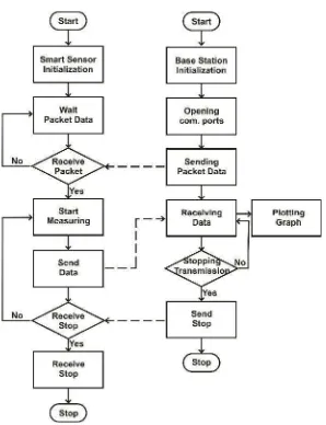
Figure 2. Flowchart Communication System Smart Sensor and Base Station
3. Design of the System
3.1.
Vibration Sensor Module
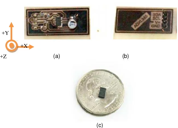
Vibration sensor used in proposed system is MEMS accelerometer produced by Analog Devices ADXL345 which is small, thin, lightweight, and low cost. It can measure static and dynamic acceleration that can be used to measure vibration on 3 axis direction XYZ and can give a digital output with high resolution (13bit) directly. Moreover, it can be used to measure vibration with selectable measurement range / g-select ( ±2, ±4, ±8, ±16g ) through serial communication SPI (3 or 4 Wire) or two-wire digital interface I2C [4]. The block diagram of MEMS accelerometer ADXL345, and the presentation of this sensor are depicted in Figures 3 and 4, respectively.
ISSN: 1693-6930 420
Figure 3. Blok Diagram ADXL345.
(a) (b)
(c)
Figure 4. Sensor Module Accelerometer 3 axis ADXL345 (a) Top View (b) Bottom View (c) MEMS accelerometer ADXL345
3.2. Wireless Smart Sensor
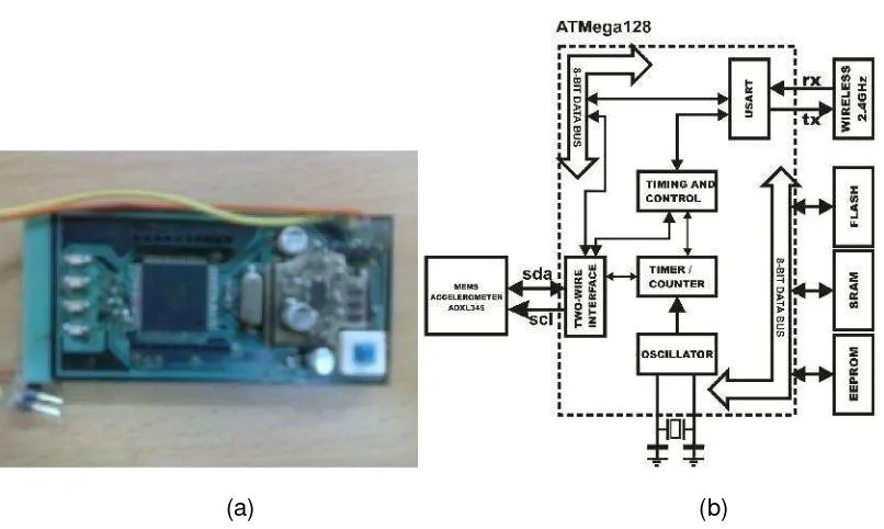
Wireless smart sensor consists of three parts which are accelerometer sensor module, wireless communication 2.4 GHz module and a microprocessor. Almost all activities of the wireless smart sensor are controlled by microprocessor ATmega128 such as vibration data acquisition from accelerometer ADXL345 through serial communication I2C, arithmetic’s operation, communication and wireless data transmission with base station. ATmega 128 is a powerful 8bit microcontroller which has some feature such as 128Kbytes programmable flash, 4Kbytes EEPROM, 4Kbytes SRAM, 8channel 10bit ADC, and etc. [9]. Figure 5a and 5b show overall block diagram from wireless smart sensor and the proposed mainboard of wireless sensor, respectively.
+X +Y
(a)
(b)
Figure 5. Wireless smart sensor: (a) Block Diagram; (b) Main Board
3.3. Base Station
Base Station is a data recipient station that consist of a PC and a device that can be communicate in two way with the wireless smart sensor. Base station hardware is also equipped with wireless 2.4GHz module so it can transmit/received data from wireless smart sensor; serial data that received through this wireless transmission is then converted to standard USB packet with USB to Serial Converter FT232BL. Base Station block diagram can be seen on Figure 6.
(a) (b)
Figure 6. Base Station: (a) Block Diagram; (b) Hardware
3.4. Software of Signal Processing
Digital signal processing from the accelerometer data are doing with plotting the data into time and frequency domain.
3.4.1. Amplitude Determination
ISSN: 1693-6930 422
3.4.2. Frequency calculation
For the necessity of digital signal analysis, practically time domain signals need to be converted to frequency domain signals with Fourier transforms. Discrete Fourier Transform (DFT) changed the N samples real data x0,…xN-1 to become complex number X0,…XN-1 in
But in reality the use of DFT formula to convert data from time domain to frequency domain had a problem, if the data to be converted to frequency domain is in a large number it will require a lot of operation to doing vector matrix multiplication ⃗ and would take O(N2) operations for N data samples. To solve this problem, the DFT can be calculating using FFT algorithm that would reduce DFT fromO(N2) to becomeO(N log2N) operation [10].
4. Result and Discussion
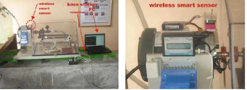
Finally, test have been performed on wireless smart sensor and base station, as can be seen on Figure 7 wireless smart sensor and base station are tested on the machine fault simulator (MFS) where the wireless smart sensor are attached on AC motor. When the machine is turned on, the motor will produce vibration and then this will be measured by wireless smart sensor and then the data will be transmitted wirelessly to the base station which is separated on the other side from the machine.
Figure 7. Laboratory test of wireless smart sensor on the machinery fault simulator
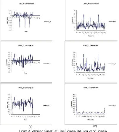
Figure 8 shows result of the experiment, from here wireless smart sensor worked well, it can sense the vibration from the system in 3 axis XYZ. The vibration data is then transmitted to the base station and then it displayed on the PC as a time domain graph in real-time systems.
Figure 8. Vibration data plotted in the time domain signal
ISSN: 1693-6930 424
5. Conclusion
Vibration based condition maintenance is an efficient way to determine the condition of a system. It can eliminated the need for the scheduled maintenance which in theory will add the cost of the maintenance, with this method we can determine the internal condition from while the system is operating. Therefore, the development of wireless smart sensor to measuring vibration on the system is a good way to implement the vibration based condition monitoring methods. The wireless smart sensor in this paper can sense the vibration in the system on 3 axis XYZ and communicate via wireless with a device and a PC called base station, which used to analyze the vibration data acquired from wireless smart sensor. Furthermore, on the next research, the wireless smart sensor will be developed to build a sensor networks that communicate each other via wireless data bus called wireless sensor networks that not only senses the vibration parameter on the system but can senses the other parameter that can determined the internal condition on the system.
Acknowledgements
Authors gratefully acknowledge to Faculty of Engineering, Diponegoro University for financial support of this study through program Penelitian Hibah Bersaing-Pengembangan Teknologiwith Contract No. 3707/UN7.3.3/PG/2012.
References
[1] Randall, Robert Bond. Vibration Based Condition Monitoring. West Sussex: John Willey & Sons Ltd. 2011.
[2] Andrew KS Jardine, Daming Lin, Dragan Banjevic. A review on machinery diagnostics and prognostics implementing condition-based maintenance. Mechanical Systems and Signal Processing. 2006; 20(7): 1483-1510.
[3] Joel R, William L, Cleghorn, James KM. Design and Analysis of a low frequency MEMS vibration sensor for automotive fault detection.International Journal of Vehicle Design.2010; 54(2): 93-110. [4] Analog Devices, Accelerometer 3 axis ADXL345, available on http://www.analog.com
[5] C McLean, D Wolfe. Intelligent wireless condition-based maintenance, In Sensors, 2002.
[6] M Ziani, M Bennouna, M Amamou, M Barboucha,The Smart Sensor Design in Industrial Processes Applications, In The 10th IEEE Mediterranean Electrotechnical Conference. 2000.
[7] FL Lewis.Smart Environments: Technologies, Protocols, and Applications. New York: John Willey & Sons Ltd. 2005.
[8] XBee Series 2 OEM RF Modules, available on http://www.MaxStream.net
[9] 8bit microcontroller with 128Kbytes In-System Programmable Flash, Datasheet ATmega128. Available on www.atmel.com.