i
Analysis on Optical Waveguide (Free Space Optics) via Beam Propagation Method (BPM)
TAN XIN MEI
This report is submitted in partial fulfillment of the requirement for the award of Bachelor of Electronic Engineering (Wireless Communication) With Honors
Faculty of Electronic and Computer Engineering Universiti Teknikal Malaysia Melaka
ii
UNIVERSTI TEKNIKAL MALAYSIA MELAKA
FAKULTI KEJURUTERAAN ELEKTRONIK DAN KEJURUTERAAN KOMPUTER
BORANG PENGESAHAN STATUS LAPORAN PROJEK SARJANA MUDA II
Tajuk Projek :
Analysis on Optical Waveguide (Free Space Optics) via Beam Propagation Method (BPM).
Sesi
Pengajian : 1 0 / 1 1
Saya ………TAN XIN MEI……… (HURUF BESAR)
mengaku membenarkan Laporan Projek Sarjana Muda ini disimpan di Perpustakaan dengan syarat-syarat kegunaan seperti berikut:
1. Laporan adalah hakmilik Universiti Teknikal Malaysia Melaka.
2. Perpustakaan dibenarkan membuat salinan untuk tujuan pengajian sahaja.
3. Perpustakaan dibenarkan membuat salinan laporan ini sebagai bahan pertukaran antara institusi pengajian tinggi.
4. Sila tandakan ( √ ) :
SULIT*
*(Mengandungi maklumat yang berdarjah keselamatan atau kepentingan Malaysia seperti yang termaktub di dalam AKTA RAHSIA RASMI 1972)
TERHAD** **(Mengandungi maklumat terhad yang telah ditentukan oleh
organisasi/badan di mana penyelidikan dijalankan)
TIDAK TERHAD
Disahkan oleh:
__________________________ ___________________________________
(TANDATANGAN PENULIS) (COP DAN TANDATANGAN PENYELIA)
Tarikh: ……….. Tarikh: ………..
iii
“I hereby declare that this report is the result of my own work except for quotes as cited in the references.”
iv
“I hereby declare that I have read this report and in my opinion is sufficient in terms of the scope and qualify for the award of Bachelor of Electronic Engineering
(Wireless Communication) With Honors.”
v
vi
ACKNOWLEGDEMENT
vii
ABSTRACT
viii
ABSTRAK
ix
TABLE OF CONTENTS
CHAPTER TITLE PAGE
PROJECT TITLE i
PROJECT STATUS VERIFICATION FORM ii
DECLARATION iii
VERIFICATION OF SUPERVISOR iv
DEDICATION v
ACKNOWLEDGEMENT vi
ABSTRACT vii
ABSTRAK vii
TABLE OF CONTENTS ix
LIST OF TABLES xii
LIST OF FIGURES xiii
LIST OF ABBREVIATION xv
LIST OF APPENDIXES xvi
I INTRODUCTION
1.1 Introduction of FSO 1
1.2 Project Objective 2
1.3 Problem Statement 3
1.4 Project Scope 3
1.5 Brief Explanation of Methodology 4
x
II LITERATURE REVIEW
2.1 What is Free Space Optics 5
2.2 History of FSO 6
2.3 How FSO Works 8
2.4 Advantages of FSO 12
2.5 Limitations of FSO 13
III METHODOLOGY
3
3.1 Project Methodology
16
3.2 Simulation-assisted Design of FSO Communication Link
18
3.2.1 OptiSystem Software 18
3.2.2 FSO Link Design 20
3.2.3 Information Obtained
1. Transmit Power 23
2. Optical Spectrum of Directly Modulated Laser
23
3. Optical Spectrum of FSO Channel 24 4. Optical Power Meter at FSO Channel 25
5. Received Signal 26
6. Eye Diagram 27
IV RESULT AND DISCUSSION
3.3Nonlinear Schrödinger Equation 28
3.4Rainfall Attenuation 29
3.5Scattering Effect 36
xi
3.7Atmospheric Effect 43
3.8Sum up all Effects 45
3.9Result Analysis 48
V CONCLUSION
3.10 Conclusion 50
3.11 Recommendation 51
REFERENCES 52
APPENDIX 54
xii
LIST OF TABLES
NO TITLE PAGE
3.1 Equipments and parameters used in FSO link simulation 21
3.2 Analysis tools used in FSO link simulation 22
4.1 Rainfall distribution 29
4.2 Rainfall attenuation comparison 35
4.3 Particle size distribution 37
4.4 Atmospheric Condition 43
4.5 Comparison of attenuation and power transmit required under different weather effects
xiii
LIST OF FIGURES
NO TITLE PAGE
2.1 Historical photos of FSO 7
2.2 FSO transceiver device, old and new design 8
2.3 Basic FSO Principle 9
2.4 Electromagnetic Spectrum and Visible Spectrum 10
2.5 FSO Application 11
2.6 Rain droplet 14
2.7 Fog effect 14
2.8 FSO Limitation Factors 15
3.1 Portion of OptiSystem library devices 19
3.2 Simulation setup of FSO link using OptiSystem 20
3.3 Transmitted signal 23
3.4 Optical Spectrum of Directly Modulated Laser 24
3.5 Optical Spectrum of FSO channel 25
3.6 Optical Power Meter 25
3.7 Received signal 26
3.8 Eye Diagram 27
4.1 Weak rain attenuation simulation result 30
4.2 Weak rain attenuation= 2.9dB/km 31
4.3 Relationship between signal power and range (Rain effect) 32 4.4 Distorted eye diagram caused by rain attenuation 33
4.5 Clear eye diagram with minimum Pt ≥ 25dBm 33
4.6 Normal rain simulation result 34
xiv
4.8 Scattering effect simulation result 37
4.9 Relationship between signal power and range (Scattering Effect) 38
4.10 Clear eye diagram with minimum Pt ≥20dBm 39
4.11 Scintillation as a result of variation of refractive index of air 40
4.12 Scintillation effect simulation result 41
4.13 Clear eye diagram with minimum Pt ≥28dBm 42
4.14 Clear air condition simulation result 44
4.15 Clear eye diagram with minimum Pt ≥19dBm 45
4.16 All effects simulation result 46
4.17 Relationship between signal power and range (Overall effect) 47
xv
LIST OF ABBREVIATION
BER - Bit error rates
FSO - Free Space Optics
IrDA - Infrared Data Association
LAN - Local Area Network
LED - Light-emitting diodes
xvi
LIST OF APPENDIX
NO TITLE PAGE
1
CHAPTER I
INTRODUCTION
This chapter includes an introduction of Free Space Optics (FSO), project objectives, problem statement, and project scope, as well as brief explanation of methodology and report structure.
1.1 Introduction of FSO
2
Free-space optical communications has a number of applications, such as to become a last (or first) mile telecommunications link, as a LAN link between buildings, as a LAN link within a room using diffusive optic, for communications between spacecraft, including elements of a satellite constellation and for interstellar communication.
However there are a variety of deleterious features of the atmospheric channel that may lead to serious signal fading and even complete loss of signal. This results in increased system bit error rates (BERs). The primary factors affecting performance include atmospheric attenuation, scintillation, building motion, and physical obstructions. Several simulations using simulation tools are carried out to further investigate FSO system performance.
1.2 Objectives
The first objective of the project is to study and understand the performance of FSO communication system as a point to point wireless communication. This includes studying of how the system works and clarifying its advantages’ and disadvantages in the daily application.
The second objective is to study the atmospheric weather effects on the propagation of optical beam in the waveguide (or FSO). These effects are rain attenuation, scattering effect, scintillation effect and atmospheric effect which limiting the maximum data rate of the system. Define the realistic performance limitations of FSO regard to atmospheric considerations is important.
3
1.3 Problem Statement
While fiber-optic cable and FSO technology share many of the same attributes, they face different challenges due to the way they transmit information. While fiber is subject to outside disturbances from wayward construction backhoes, and even sharks when deployed under sea, FSO technology is subject to its own potential outside disturbances.
Optical wireless networks based on FSO technology must be designed to combat changes in the atmosphere, which can affect FSO system performance capacity. And because FSO is a line-of-sight technology, the interconnecting points must be free from physical obstruction and able to "see" each other. Among the issues to be considered when deploying FSO-based optical wireless systems are fog which leads to absorption and scattering, scintillation, atmospheric turbulences, physical obstructions and building sway.
These effects degrade the quality of communication link and resulting of increasing BER. Therefore there exists the need for accurate channel characterization in order to understand and mitigate the problem.
1.4 Project Scope
A few guidelines are proposed so that this project is narrowed to a certain
boundaries. This will ensure that this project achieves its objectives. First part of the
project is focused on literature review and study of FSO communication system, the technology deployed, and the advantages and limitation of FSO as high bandwidth wireless communication technology.
4
1.5 Brief Explanation of Methodology
Firstly all the information gathered for this project is through research via internet and library, the material includes journal paper, articles from books, thesis paper, and internet references.
OptiSystem and MATLAB software are introduced as simulation tool in this project. OptiSystem is used to design the FSO communication link while Matlab is used to simulate different atmospheric weather effects on FSO signal propagation.
1.6 Report Structure
First chapter of the report is about project introduction. FSO has been of interest in recent years due to the increase in demand for high data link speed, especially in urban area. However it suffers from adverse weather conditions such as fog and rain. Therefore the objective of the project is to study and simulate an accurate FSO model to show the weather effects on propagation of optical signal.
Second chapter covers the literature review of FSO system, the development of FSO communication, the technology used and also benefits and limitation of this emerging technology. Understanding on this chapter helps in the simulation in the chapter later.
Research methodology is explained detail in the third chapter. The chapter shows how the simulations tools are being utilized in doing the simulation. It includes the simulation specification.
Results from simulation are presented in the fourth chapter. Comparison and analysis are made regarding to the result obtained.
5
CHAPTER II
LITERATURE REVIEW
This chapter will describe details about Free Space Optics (FSO), literature review on the history of FSO, basic principles, how does FSO works, advantages and performance limitation of FSO.
2.1 What is Free Space Optics (FSO)
Free-Space Optics (FSO), also called Optical Wireless OW) is a line-of-sight technology that uses lasers to provide optical bandwidth connections. It refers to the transmission of modulated visible or infrared (IR) beams through the atmosphere to obtain broadband communications. FSO systems can function over distances of several kilometers. As long as there is a clear line of sight between the source and the destination and enough power transmitted, communication is theoretically possible.
Currently, FSO offers capacities in the range of 100Mbps to 2.5Gbps of data, voice and video communications through the air, allowing optical connectivity without requiring fiber-optic cable or securing spectrum licenses. These systems are compatible with a wide range of applications and markets since they are sufficiently flexible as to be easily implemented.
6
lasers is a simple concept similar to optical transmissions using fiber-optic cables; the only difference is the medium. Light travels through air faster than it does through glass, so it is fair to classify FSO as optical communications at the speed of light. FSO is all-optical without the labor of digging up sidewalk to install a fiber link and it requires no government licensing and can be readily deployed within hours of the availability of line-of-sight access. This means no hassles, no backlog, and no intermediary devices to the fiber backbone.
FSO technology is relatively simple. It's based on connectivity between FSO units, each consisting of an optical transceiver with a laser transmitter and a receiver to provide full duplex (bi-directional) capability. Each FSO unit uses a high-power optical source (i.e. laser), plus a lens that transmits light through the atmosphere to another lens receiving the information. The receiving lens connects to a high-sensitivity receiver via optical fiber. FSO technology requires no spectrum licensing. FSO is easily upgradeable, and its open interfaces support equipment from a variety of vendors, which helps service providers protect their investment in embedded telecommunications infrastructure.
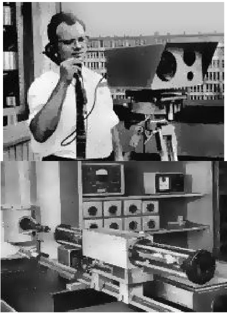
2.2 History of Free Space Optics (FSO)
The engineering maturity of Free Space Optics (FSO) is often underestimated, due to a misunderstanding of how long Free Space Optics (FSO) systems have been under development. Historically, Free Space Optics (FSO) or optical wireless communications was first demonstrated by Alexander Graham Bell in the late nineteenth century (prior to his demonstration of the telephone!). Bell’s Free Space Optics (FSO) experiment converted voice sounds into telephone signals and transmitted them between receivers through free air space along a beam of light for a distance of some 600 feet. He named his experimental device the “photo phone,” as shown in Figure 2.1. Bell considered this optical technology – and not the telephone – his pre-eminent invention because it did not require wires for transmission [1].
7
engineering of today’s Free Space Optics (FSO) or free space optical communications systems was done over the past 40 years or so, mostly for defense applications. By addressing the principal engineering challenges of Free Space Optics (FSO), this aerospace/defense activity established a strong foundation upon which today’s commercial laser-based Free Space Optics (FSO) systems are based.
[image:23.595.207.433.400.712.2]In the mid-1960’s, the military and NASA initiated experiments to utilized the laser as a means of communication between the Goddard Space Flight Center and the Gemini-7 orbiting space capsule. FSO has been used for more than 30 years to provide fast communication links in remote locations. While fiber-optic communications has gained acceptance in the telecommunications industry, FSO communications is still relatively new. FSO technology enables bandwidth transmission capabilities that are similar to fiber optics, using similar optical transmitters and receivers and even enabling WDM-like technologies to operate through free space.
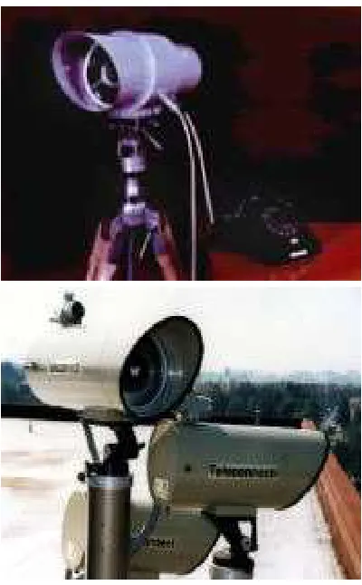
8
Figure 2.2: FSO transceiver device, old and new design
2.3 How Free Space Optics (FSO) Works?
FSO involves the optical transmission of voice, video, and data using air as the medium of transmission as opposed to fiber optic cable. FSO technology is relatively simple. It's based on connectivity between FSO-based optical wireless units, each consisting of an optical transceiver with a laser transmitter and a receiver to provide full-duplex (bi-directional) capability, as shown in Figure 2.3.