The 24th Computational Fluid Dynamics Symposium F7-5
Copyright © 2010 by JSFM 1
On the aerodynamic damping mechanism of vehicle pitching stability
using Large Eddy Simulation
o CHENG, S.Y., Hokkaido University, N-13, W-8, Kita-ku, Sapporo: [email protected] TSUBOKURA, M., Hokkaido University, N-13, W-8, Kita-ku, Sapporo: [email protected]
NAKASHIMA, T., Hiroshima University, 1-4-1 Higashi-Hiroshima, Hiroshima: [email protected] NOUZAWA, T., Mazda Motor Corporation, Aki Gun, Hiroshima: [email protected]
OKADA, Y., Mazda Motor Corporation, Aki Gun, Hiroshima: [email protected]
Large eddy simulation was conducted to investigate the pitching stability characteristic of notchback-type vehicle. In this paper, two simplified vehicle models represent the notchback of different pitching stability characteristics were used. Numerical method adopted was validated by comparing the simulation result with wind tunnel data. To probe the dynamic response of the models, forced-sinusoidal-pitching oscillation is imposed and the resulting pitch moment is phase averaged, and decomposed into the stationary, quasi-stationary, and dynamic components for assessment. Vehicle model of higher aerodynamic damping is found to exhibit two-dimensional flow structure above the central region of its trunk deck, whereas vehicle model of lower aerodynamic damping is associated with strong cross flow and upwash circulatory flow structure. The outcome of this work demonstrates how unsteady aerodynamics can be exploited for the control of vehicle’s straight ahead stability.
1. Introduction
In this study, we conducted Large Eddy Simulation (LES) on flow past two vehicle models to investigate their pitching stability characteristics. During the LES, sinusoidal-forced-pitching oscillation was imposed on the vehicle models to probe their dynamic responses. The computed pitch moment was phase averaged, and decomposed to estimate their aerodynamic damping factors. Then, flow visualization was performed to examine the damping mechanism which results in different pitching stability behaviors between the notchback models. 2. Numerical Methods
2-1 Governing equations and discretization
The CFD code FrontFlow/red ver. 2.8 which has been optimized for transient vehicle aerodynamics study was used for the LES calculation. The governing equations being solved are spatially filtered continuity and Navier-Stokes equations. The subgrid-scale eddy viscosity is modeled by the standard Smagorinsky model, with the model coefficient Cs of 0.15. The Van Driest dumping function was adopted for the dumping of the effect of sub-grid-scale eddy viscosity in the vicinity of solid boundary. The governing equations are discretized by using the vertex-centered unstructured finite volume method. The second-order central differencing scheme was applied for the spatial derivatives and blending of 5% first-order upwind scheme for the convection term was exploited for numerical stability. For time advancement, Euler implicit scheme was used. The pressure-velocity coupling was preserved by using SMAC (Simplified Marker and Cell) algorithm.
2-2 Simplified Vehicle Models
The simplified models are of simple body shapes which represent real notchback type vehicles of different pitching stability characteristics. The models are of similar height H, width W, and
length L measurements (210mm x 80mm x 65mm). The main
characteristic differences between the models are at the front and rear pillar shapes; Sharp-edged front pillar coupled with curved rear pillar for model representing the notchback of lower pitching stability, and vice versa (see Fig. 1(a) and (b)). However, both
models are having the same slant angles of 30° and 25° for the
front and rear pillars, respectively. In order for convenient in the discussions, the vehicle model represents the vehicle of higher pitching stability is designated as model H , while the other model is termed model L , hereafter.
Fig. 1 Simplified vehicle models
2-3 Computational domain and boundary conditions
The shape of the computational domain is of a rectangular duct, which covered 3.14L upstream of the vehicle model, 6.86L
downstream, 4.0W on both sides, and a height of 7.2H. It
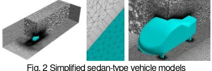
encompasses of 16 million elements with 5 million nodes. In addition, finer elements are constructed nearby the vehicle models to capture more details of the flow information around the vehicles (see Fig. 2). Fifteen layers of prism mesh are generated from the surface of the vehicle models with the thickness of the first layer being 0.1 mm. The typical wall distance of the first nearest grid point is less than 150 in the wall unit (y+), which is within the logarithmic layer of the mean velocity profile.
Fig. 2 Simplified sedan-type vehicle models
At the inlet boundary, the approach flow was set to be a constant, uniform velocity of 16.7 m/s, corresponding to Reynolds number, Re of 2.3 x 10⁵ based on the vehicle model length L. At the outflow
The 24th Computational Fluid Dynamics Symposium F7-5
Copyright © 2010 by JSFM 2
suction floor effect which prevent the development of boundary layer, while the remaining ground surface was treated by the wall-model assuming a fully developed turbulent boundary layer. As for the surface of the vehicle models, the log-law distribution of instantaneous velocity was imposed. Finally, the ceiling and lateral boundaries of the domain were treated as free-slip wall boundary. 2-4 Forced pitching oscillation setting
In order to probe the transient response of the models during pitching, a forced-sinusoidal-pitching oscillation is imposed on the models during LES. This is achieved by employing the Arbitrary Lagrangian-Eulerian (ALE) technique. The axis of rotation is at the location corresponds to where front wheel axle is situated in the case of a real vehicle. The pitch angle θ is defined as θ = θ0 + θ1 sin(2πft). By setting θ0 and θ1 equaled to 2, the vehicle
models were forced to oscillate between 0° to 4°. The
frequency f is 10 Hz, which is equivalent to the Strouhal number St of 0.13. Phase-averaged results presented in this paper are the averaged of 15 cycles after the LES computation achieved stable periodic conditions.
3. Results and Discussion
3-2 Aerodynamic damping characteristics
Phase-averaged M acting on model L and H during
forced-sinusoidal-pitching oscillation is as shown in Fig. 3. It can be decomposed into three parts as, M = Cstat + Csin sinφ(t)+ Ccos Cosφ(t) where, Cstat, Csin, and Ccos are numerical coefficients to be determined by fitting the non-linear function to the M data sets.
Details in the derivation of the function are as described by Nakashima et al. [1]. The approximated coefficients are presented in Table 1. Since the imposed displacement of the models is given in sine function, thus only the third component has effect on the pitching motion. As depicted, the Ccos values are having negative
sign, thus the effect they produce are resistant of pitching motion, i.e. damping of pitching instability. Between them, Ccos of model H
is higher. Therefore higher aerodynamic damping may be anticipated in model H. This trend is in agreement with our expectation as model H is created based on the notchback of higher pitching stability.
(a) Model L (b) Model H
Fig. 3 Phase-averaged pitching moment and their approximations Table 1 Approximated coefficients for components of M
Model Cstat Csin Ccos
L 1.39 x 10⁻² 2.59 x 10⁻³ -4.53 x 10⁻³
H 1.17 x 10⁻² 2.33 x 10⁻³ -6.69 x 10⁻³
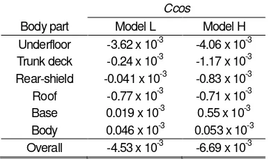
3-3 Contribution of Body Parts in Aerodynamic Damping
The contributions of each body part in Ccos for both models are
given in Table 2. As illustrated, the approximated coefficients of the rear shield, roof, base, and body are rather small (by an order of magnitude or two), thus contribution to the dynamic response of
the models is mainly depends on the proportion made by the underfloor and trunk deck. Between the two models, percentage difference in the approximated coefficients of the underfloor is only accounted for about 12%, while 132% for the trunk deck. Hence, it can be deduced that the primarily factor that contributes to the different of pitching stability characteristic between the models is trunk deck. The relatively smaller percentage difference in the underfloor can be associated to the same flat underfloor configuration of the models.
Table 2 Approximated coefficients for body part contributions
Ccos
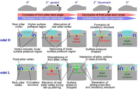
3-4 Aerodynamic damping mechanism
Figure 4 shows the schematic diagram of aerodynamic damping mechanism. The first row of the diagram illustrates the dependency of front and rear pillars’ slant angle with pitch angle. As depicted, during tail-up pitching, the slant angle of front pillar increases, while the rear pillar’s slant angle decreases. Meanwhile, an opposite trend occurred during tail-down pitching. The second and third rows of the diagram illustrate the transient characteristic of flow structures above the rear section of the models during pitching oscillation and the associated vortex-induced surface pressure.
In general, the flow above the rear section of model H was dominated by a pair of rear pillar vortices near the side edges, while away from the vicinity of the side edges, the flow appeared uniform. During tail-up pitching, the strength of rear pillar vortices decreases owing to the decreased of the slant angle of rear pillar edges. Consequently, the vortex-induced, low surface static pressure region at the side of the trunk deck has narrowed down, and causes the increased of the overall trunk deck pressure force, thus produces the tendency for the aerodynamic force to refrain the pitching motion in model H.
During tail-down pitching, i.e. at 2° downward, a circulatory
structure is formed near the central region above the trunk deck. Hence, the static pressure drops and causes the corresponding dropped of surface pressure force at the central region of the trunk deck. Accordingly, a tendency for the aerodynamic force to restrain the tail-down pitching motion is produced.
The 24th Computational Fluid Dynamics Symposium F7-5
Copyright © 2010 by JSFM 3
brings the vortices into close proximity with the front pillar vortex. These vortices that rotate in direction opposite one another, generates a strong cross flow above the trunk deck by drawing in air from the side, flowing through them and towards the center line. As the cross flow converges at the center line, they rolls upwards and forms an upwash inducing, circulatory structure. Attributed to this strong cross flow, thus the induced surface pressure force on the trunk deck diminishes.
During tail-down pitching however, the strength of the front pillar vortex attenuates owing to the decreases of the front pillar slant
angle, and the rear pillar vortex has been brought farther away, thus their interaction lessen, so as the corresponding cross flow and the circulatory structure. Hence, the static pressure of the flow field increases and causes the induced pressure force on the trunk deck to increase. Attributed to this, a tendency for the aerodynamic force to enhance the tail-down pitching motion of model L is produced.
Fig. 4 Schematic diagram of aerodynamics damping mechanism for pitching of notchback models; cross-sectional plane are perpendicular to streamwise direction, at midsection of the trunk deck; Viewpoint from the back of the models.
4. Conclusion
Effect of unsteady flow structures above the rear section of notchback vehicles on their pitching stability was investigated using LES. Aerodynamic damping mechanism has been identified through visualization of phase-averaged result.
Outcome of this study shows that atop of the implementation of mechanical system for vehicle stability control, damping of pitching instability can be attained by exploiting the effect of unsteady aerodynamics, which is mainly controlled by the front and rear pillar shape configurations. In particular, curved front pillar coupled with sharp-edged rear pillar configuration was able to produce a tendency for unsteady aerodynamic force to restrain the vehicle’s pitching motion. On the contrary, the presence of front pillar vortices, which is associated with sharp-edged front pillar configuration, tends to enhance pitching instability.
Acknowledgments
This work was supported by the 2007 Industrial Technology Research Grant program from the New Energy and Industrial
Technology Development Organization (NEDO) of Japan. Development of the base software FFR was supported by the FSIS and “Revolutionary Simulation Software (RSS21)” projects sponsored by MEXT, Japan. The first author’s Ph.D. program is sponsored by Ministry of Higher Education and Universiti Teknikal Malaysia Melaka, Malaysia.
Reference