MANEUVER FIRE FLASHOVER ROBOT
YUNUS BIN YUSOFF
MANEUVER FIRE FLASHOVER ROBOT
YUNUS BIN YUSOFF
This Report Is Submitted In Partial Fulfillment Of Requirements For The Bachelor Degree of Electronic Engineering (Industrial Electronic)
Faculty of Electronic and Computer Engineering University Teknikal Malaysia Melaka
ii
CANDIDATE’S DECLARATION
I admit this work is my own work, except for each extract and summary that I have explain its source.
Signature :
Name : YUNUS BIN YUSOFF
iii
CONFORMATION
I admit that I read this work. In my opinion this work was adequate from scope and quality of “Project Sarjana Muda” (PSM) report, Bachelor of Electronic Engineering (Electronic Industry).
Signature :
Name : SITI AISYAH BINTI ANAS
iv
v
ACKNOWLADGMENT
The special thank goes to my helpful supervisor, Miss. Siti Aisyah binti Anas. The supervision and support that he gave truly help the progression and smoothness of the internship program. The co-operation is much indeed appreciated. All projects during the program would be nothing without the enthusiasm and guide from you. I would like to take this opportunity to thank to the authority of University Teknikal Malaysia Melaka (UTeM) for providing me with a good environment and facilities to complete this project.
vi
I also want to thank to the Faculty of Electronic and Computer Engineering for offering this subject, Bachelor Degree Project. It gave me an opportunity to manage my time and learn about the method used to develop any electronic system circuit by using several application either hardware analysis or software analysis. In addition, I would also like to thank to PSM laboratory that I used to make my project more successfully.
vii
ABSTRACT
viii
ABSTRAK
ix
xi
1.4.2.4 Omni wheel sequence movement 7 1.4.2.5 Communication between digital
1.4.2.2 IR sensor components 8
1.4.2.3 Fire extinguish component 9 1.5 A brief description of the methodology 9
1.6 Structure of project 10
II LITERATURE REVIEW
2.1 Overview 11
2.2 Roomba robot 11
2.3 NlsbRlO963 omnidirectional mobile robot 13 2.4 Holonomic control with omnidirectional drive 15
2.5 Maze solving robot (MSR) 17
III METHODOLOGY
3.1 Introduction 21
3.2 Stage 1: Study of the project 22
3.3 Stage 2: Appropriate circuit design and test 23
3.3.1 Omni wheel 24
xii
IV RESULT AND ANALYSIS
4.1 Overview 31
4.2 Design and simulation 32
4.2.1 Motor driver 32
4.2.2 IR sensor 37
4.2.3 PIC16F877A and digital compass 39
xiii
LIST OF TABLE
No Title Page
2. 1 LSRB algorithm process (mapping path) 18
4.1 Orientation of omni wheel with it response movement 34
4.2 Input configuration instruction 38
4.3 Location and effect for HMC6352 data reading 53 4.4 Shown the result for the whole project circuit 57
xiv
LIST OF FIGURE
No Title Page
1.2.1 Skid steering 3
1.2.2 Coordinate (Ackerman) steering 3
1.2.3 Robots center of gravity 4
1.4.1 Scope of project (main component) 6
2.1 Roomba robot returning to the charging dock 12
2.2 Navigation formula 13
2.3 NlsbRlo963 system overview 14
2.4 Mobile robot with gripper 15
2.5 Arrangement of the wheels and distribution of forces in symmetrical
16
3.1 Flow chart of the project 22
3.2 Simulation motor drive 24
3.3 Circuit design for testing digital compass 25
3.4 Connection between IR sensors with IC comparator 27
3.5 Overall system communication diagram 29
3.6 Combination of circuit component 29
3.7 Initial robot development concept 30
4.1 Connection between L293D and PIC16F877A 33
xv
4.4 Initial setup for PIC16F877A 36
4.5 Initial operation setup 36
4.6 Main operation for the motor driver 36
4.7 PIC connection for IR sensor 37
4.8 Connection between IR sensor and LM324 38
4.9 Initial setup for PIC 39
4.10 Initial operation setup 39
4.11 Main operation for the IR sensor 39
4.12 Connection between HMC6352 and PIC16F877A 40
4.13 I2C communication for HMC6352 41
4.14 Initial setup for PIC 41
4.15 Initial operation with main operation for the HMC6352 42 4.16 (a) PCB layout in PROTEUS window and (b) PCB
layout for the etching process for motor driver
43
4.17 (a) PCB layout in PROTEUS window and (b) PCB layout for the etching process for IR sensor
43
4.18 (a) PCB layout in PROTEUS window and (b) PCB layout for the etching process for PIC
44
4.19 PCB tracking development for (a) motor driver, (b) IR sensor and (c) PIC16F877A
45
4.20 UV light expose machine 46
4.21 Developing process for positive board 46
4.22 Etching machine 47
4.23 C40R with current calculation 48
4.24 L298 motor driver schematic layout 49
4.25 L298 motor driver PCB layout 49
4.26 Pin A4 response 50
4.27 New orientation response 51
4.28 Additional IR sensor connection 52
4.29 Two LM324 with eight IR sensor 52
xvi
LIST OF SHORT FORM
PIC – Peripheral interface circuit
AC – Alternate current
DC – Direct current
PWM – Pulse width modulation
IR – Infra red
PCB – Printed circuit board LCD – Liquid-crystal display LED – Light-emitting diode IC – Integrated circuit
V – Volt
MHz – Mega Hertz
MB – Mega byte
DRAM – Dynamic random access memory PID – Proportional integral derivative
xvii
SCL Serial clock
SDA Serial data
UV Ultraviolet
xviii
LIST OF APPENDIX
No Title Page
A PIC16F877A instruction for HMC6352 70
B PIC16F877A instruction for movement 71
C PIC16F877A instruction for returning to the initial area 72
D Data sheet HMC6352 75
E Data sheet L298 88
F Data sheet LM324 100
CHAPTER 1
INTRODUCTION
This chapter consists of introduction, problem statement, objective, scopes, brief description of the methodology and structure of project. By completing this chapter, it will provide the information and the structure for project.
1.1 Introduction.
2
depending on type of locomotion and will become a main role in a maneuver robot when this robot use in a complex terrain application. In this project, the locomotion becomes a main role for movement not because of the complex terrain but due to increasing movement performance. The most popular locomotion use is wheeled locomotion which suitable in a low complexity terrain. It is a common combination for maneuver robot with a round wheel and this type of wheel had becomes a standard wheel. By implement this type of wheel, for make a turn normally it will turn left and right in a curve shape and static turning method. When surrounding with terrain requires sharp corner ability, it becomes a problem. The curve shape will require a large area for turning while the static turning requires an extra time to make a turn. Although it is a normal movement, the problem is it causes an extra space and time waste. Therefore, in this project a robot with a new type of wheel call omni wheel will be develops to cover this problem. An addition, a digital compass will be used as additional component to remember of path way or mapping the surrounding area.
1.2 Problem Statement.
3
Figure 1.1: Skid steering
.
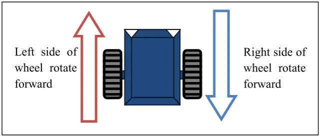
Other steering method is a coordinate (Ackerman) steering that allow robot steer in low power consumption. The low power consumption is due to the operation during the turning process as shown in Figure 1.2. The operations usually use less actuator (commonly one) to control the turning operation. When make a turn, one side of the wheels or actuator will rotate while other side will become static and in some application it will rotate in a low speed. It also require controlling pulse wide modulation or PWM when rotate both side in difference speed while make a turn. These steering methods mostly suitable for the application that moves around curve [3]. The positioning of the robot after make a turn will not precise because this steering method steers in a curve shape.
Figure 1.2: Coordinate (Ackerman) steering.
The second problem statement is due to the stability of the standard locomotion. When using a two wheel as locomotion the stability of the robot will be
4
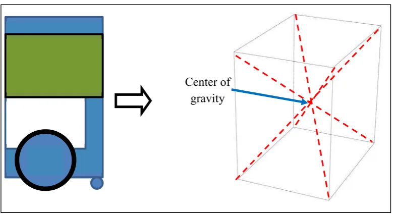
low. Then, the additional part such as castor wheel was added to increasing the stability. However, this stability was not enough because castor wheel only increase a few percent of stability. The stability of the robot more depends on the dimension of the robot. Figure 1.3 below show the current robot center of gravity that corresponding to the stability. When the center of gravity is higher, the percentage of this robot will fall down increase.
Figure 1.3: Robots center of gravity.
The third problem statement is that the robots only have one way to mapping the environment. The mapping process was a core process to ensure the mobile robots can return to its base after it moves to other place. Normally, mobile robots will memories the path that they had been through and the path includes avoiding the obstacle. When mobile robots instruct returning to the base, they will inverse their path in memory by using concept of last in, first out (LIFO). The LIFO concept is stack or queue that important in the computer science [4]. When the new obstacle present or interruption in the memory occurs, robot will lost it way for returning to the base.
The forth problem statement is regarding to the power consumption due to the motor for vacuum. A vacuum is use to lift up ping pong ball into the robot’s
5
container. By using the vacuum, a high power supply needs to be used to ensure it operational. However, power supply that use was a DC battery and by vacuum itself will drain the battery faster. Since the battery will drain faster, the other operation will interrupt and lead to malfunction of overall system.
1.3 Project Objectives.
The objectives of this project are as below:
i. To develop the movement of the omni wheel for a robot’s sharp turn. ii. To develop the digital compass as a tools of remembering the path way. iii. To develop the suitable lifter of ping pong ball.