PID TUNING OF LINE FOLLOWER ROBOT USING ANDROID
SMARTPHONE
PUBLIKASI ILMIAH
Proposed as one or the requirements to complete the degree of Bachelor of Engineering at Department of Electrical Engineering, Faculty of Engineering
Universitas Muhammadiyah Surakarta
by:
AHMAD TAUFIQ MUSADDID D 400 122 005
DEPARTMENT OF ELECTRICAL ENGINEERING
FACULTY OF ENGINEERING
APPROVAL PAGE
PID TUNING OF LINE FOLLOWER ROBOT USING ANDROID
SMARTPHONE
PUBLICATION JOURNAL
by:
AHMAD TAUFIQ MUSADDID
D 400 122 005
This journal has been checked and approved by:
Supervisor
Fajar Suryawan, S.T, M.Eng.Sc.,Ph.D.
AFFIRMATION PAGE
PID TUNING OF LINE FOLLOWER ROBOT USING ANDROID
SMARTPHONE
BY
AHMAD TAUFIQ MUSADDID
D 400 122 005
Has been tested in front of The Council of Examiners Faculty of Engineering
Universitas Muhammadiyah Surakarta on 4 January 2016
and affirmed to complete the requirements
The Council of Examiners:
1.Fajar Suryawan, S.T, M.Eng.Sc.,Ph.D. (……..……..)
(Ketua Dewan Penguji)
2.Ir. Pratomo Budi Santosa, M.T. (………)
(Anggota I Dewan Penguji)
3.Dedi Ary Prasetya, M.T. (……….)
(Anggota II Dewan Penguji)
ACKNOWLEDGEMENT
With this acknowledgement I declare that in this final project, by all my knowledge, there is
no proposed final project before in same or different university before this journal is being
published.
If there is a mistake on my declaration on the future, I will be fully responsible to all my
statement.
.
Surakarta, 31 Desember 2016
Writer
AHMAD TAUFIQ MUSADDID
PID TUNING OF LINE FOLLOWER ROBOT USING ANDROID SMARTPHONE
Abstrak
Sebuah kontroler proportional-integral-derivative (PID) adalah sebuah strategi control yang umumnya digunkan pada system otomasi. Sebuah
kontroler PID menghitung sebuah nilai kesalahan yang secara kontinyu
sebagai perbedaan antara titik yang diinginkan dan hasil pegukuran yang terukur. Pengaturan PID sangatlah krusia pada setiap system yang menggunakan PID. Kesalahan pada pengaturan PID akan mempengaruhi kinerja sebuah robot. Oleh karena itu, pengaturan PID adalah langkah yang penting. Terlebih lagi, kadang-kadang itu sangatlah dibutuhkan untuk mengatur kembali parameter-parameter PID dengan kerusakan minimal pada system. Penelitian ini bertujuan untuk mewujudkan kerusakan minimal itu pada sebuah robot dengan cara pengaturan parameter PID secara nirkabel menggunakan android smartphone melalui bluetooth. Proses pengaturan PID ini dengan cara mengatur nilai proportional, integral dan derivative. Nilai-nilai parameter akan dikirim oleh android smartphone melalui Bluetooth ke system. Robot ini dikontrol oleh arduino UNO yang menerima nilai error dari sensor inframerah. Setelah mendapatkan nilai error, system akan menghitung sinyal control PID.
Kata Kunci:Android, Arduino, Bluetooth shield, embedded computing.
Abstract
A proportional-integral-derivative (PID) controller is a control strategy commonly used in automation systems. A PID controller calculates an error value continously as the difference between desired setpoint and measured value. PID tuning is a crucial process that is needed in every system that uses PID. Mistuning of PID parameters greatly affects a robot’s performance. Hence, PID tuning is a very important step. Moreover, sometimes it is desirable to tune the PID parameters with minimal intrusion to the system. This research aims to produce that minimally invasive procedure by tuning the value of PID wirelessly using android phone via bluetooth. The process of tuning PID is adjusting the proportional, integral, and derivative parameter values. The value of these parameters will be sent by an android phone through bluetooth to the robot system. The robot is controlled by Arduino UNO that receives signals from infrared sensors and then computes the error value. After obtaining the error value, the system then calculates the PID control signal.
1. INTRODUCTION
Smartphones have now become an important part of our life. Primarily used for
communication and internet access, smartphones have now found wider use, such as
automation. With its features, smartphones --especially Android ones-- become
powerful devices that controls electronic devices. Bluetooth and WiFi are two of
those features that play role on technology based-on android smartphones.
Line Follower Robot --also called Line Tracer Robot-- is a robot that moves
following specifically designed lines. Open-loop control system is a control system
that doesn't incorporate feedback. On the other hand, closed-loop control system is a
system that takes its output value as a feedback to be proceeded on the next step.
One simple control strategy on many systems is PID based control system. This
control system is a mechanism that contains three components: proportional
controller(Kp), integral controller(Ki), and derivative controller(Kd). The purpose of
most control system on a robot is to make the output and the desired output value (the
reference) to be as close as possible. In other words, we want to reduce the errors
occuring between them. In this case, we want the line follower robot tracing the lines
as close as possible. Here we use closed-loop control strategy, where the output is
fedback to the controller.
In PID control system, we need to tune the value of Kp, Ki and Kd to reach the
best setting. This process will be hard if we re-program the robot in each tuning
process. This is the reason why this research is conducted. In short, our aim is to make
android application to adjust the values of Kp, Ki and Kd of the PID controller of the
line follower robot.
2. RESEARCH METHODS
This work started in April 2016 as an undergraduate final-year project, and took
place at Universitas Muhammadiyah Surakarta. The final product was constructed
11 Volts Lipo Battery
Jumper Wires
A Piece of Wood
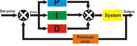
In this section we describe the general design of our line-follower robot with its
PID controller. Figure 1 describes the general functional block diagram of the robot.
The activity of this project starts from putting the robot on the line. After that we let
the robot to trace the line. From this point, we see how the robot’s performance if it is
good or bad in tracing the line. If we are not satisfied with the robot’s performance,
we can adjust it from our smartphone by changing the Kp, Ki, and Kd values. By
clicking on the Kp or Ki or Kd on the smartphone (Figure 6), the robot will stop
immediately. After stopping the robot, we are asked to input the new value of Kp or
Ki or Kd, depends on what we want. Then the robot will run again with new
adjustment.
Figure 1. System Block Diagram
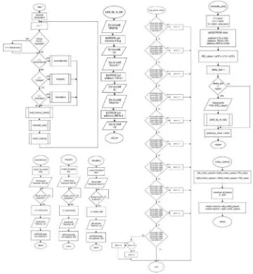
Closed-loop control system is used in the line follower robot as shown in Figure 2.
The flowchart of the system is built from a main loop system, and has some
subroutines that integrated to the main loop system. The figure 3 below shows the
flowchart of the whole system.
Figure 3. System Flowchart
This system starts from main loop, which has the role as the looping system of
whole logic built on the system. The main loop will provide all first setup, all arduino
pin initialization, serial communication initialization and all calls to subroutines. This
main loop will always loops when the power supply exists on the arduino.
We have several subroutines here, or in a more familiar terms we call it as
function. The subroutines built in this system are PID value calculation, motor
control, sensor detection, proportional call, integral call, derivative call and PID
calculate the value of PID. Motor control subroutines is functioned as motor
controlling system. Sensor subroutine is used to determine the error value in a period
of a time, so we can give this error value to PID value subroutine to be calculated as a
factor of PID value changing. Proportional call subroutine is used to wait the signal
from android smartphone as a call, when it is called, we are asked to input a new Kp
value for the system. Integral call subroutine is used to wait the signal from android
smartphone as a call, when it is called, we are asked to input a new Ki value for the
system. Derivative call subroutine is used to wait the signal from android smartphone
as a call, when it is called, we are asked to input a new Kd value for the system. PID
parameters serial printing subroutine is used to print the data of PID value and its
parameters to the android smartphone as monitoring system.
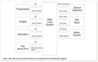
The whole connection between main loop to the whole system is not only open
loop system. This flowchart represents a closed loop control system as we know that
there is always a feedback signal occuring to correct the input to the motors. This
relation is described in Figure 4 below.
Figure 4. Flowchart Block Diagram
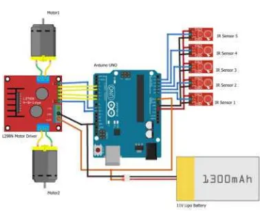
As shown in Figure 4, this robot uses 11 volts battery to power up Arduino and
motor driver. Two motors are attached to the Arduino-controlled motor driver. To
Figure 5. Robot Circuit
The design of android application used in this project is made by using
App-Inventor. It contains several buton, a text monitor and a text box.
Figure 6. Android Application Design
The logic of our android application also made on App-Inventor. Those all
statements are made by doing drag-and-drop activity, as shown in Figure 7 below.
3. RESULT AND DISCUSSION
The main idea of this project is how we can easily change PID parameters of a
robot using our android smartphone. So Firstly, we need to understand how the line
follower robot communicates with the android smartphone. In this project, we use a
bluetooth device called HC-05 as a bridge between the robot and the smartphone. By
this bluetooth media, we then use serial communication as a mean of communication
between the two devices.
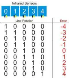
The robot works based on arduino that calculates any error occurs. The error is
sent from the condition of five infrared sensors to arduino. There error varies from -4
to 4, depends on how the sensors read the line. But the error will become -5 or 5 when
the line exceeds from the sensors reach. According to the line that can be detected by
the robot, we have nine possibilities of detection, as explained in figure 7 below. And
this figure is showing us the front look layout of our sensors location.
Figure 7. How Sensors Calculate Error
Based on figure 7, our robot movement is decided by the value of error, that is our
goal. For instance, our goal when the error is 0, is straight movement. When the error
is on negative, the robot should make right turning. The more negative we get, the
speed of right turning should be more too. And when it is positive, the goal is left
turning. The more positive we get, more speed on left turning too.
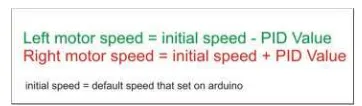
Figure 8. PID Formula
The PID value in this project is used to control two motors that attached to the
robot. After getting PID value, arduino will send certain PWM signal pattern to motor
driver (L298N). Then the motor driver amplifies the PWM signal to both motors to
control the speed. So, the relationship between PID value and motor speed is shown in
figure 8 below.
Figure 9. PID Value and Motor Speed Relation
Motor speed that produced in this robot is controlled by adjusting the duty cycle.
This duty cycle is controlled by arduino based on the calculation above. After getting
the value of the right motor and left motor, arduino will send those value to the motor
driver to be amplified. We aim to get a proper adjusment for our robot to move
following the lines. For a straight movement, the both motors should has same duty
cycles. For a right turn, the left motor should be more on duty cycle. Otherwise, a left
turn needs more duty cycle on right motor.
3.1 Efficiency Experiment
In this experiment, we will test how the robot will change its performance by
varying the Kp, Ki and Kd.
1) Kp Variation
This Kp value will tell us how the robot will respond the line, we will vary
the valu of Kp from 0 to its best value that produce its best responsivity to the
Table 1. Kp Variation
As shown in the table 1 above, we see that Kp value variation cause different
responses. When Kp value is 0, it shows that the robot doesn’t do anything
regarding to line. But when we increase it, we see that the responsivity is
changed and finally we find its best responsivity when the value reach 556. And
it is over responsive when hit more than 559.
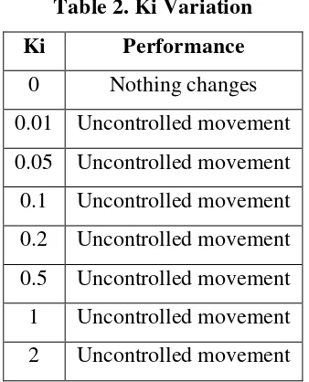
2) Ki Variation
This Ki value variation is actually causing some exponential change on the
robot. So, it is shown on table 2.
10 Uncontrolled movement
20 Uncontrolled movement
Exponential change that occurs on a system of this kind of robot is not
suitable as shown on table 2. This is because in our robot system, the error will
change in linear way. Even it is just small change there, we will realize that
giving any value on Ki, will cause any random movement to the robot, except 0.
So, the best value of Ki is 0 in this kind of robot.
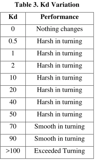
3) Kd Variation
Kd value variation is conducted to change the performance of the turning of
the robot. In this case Kd value in this project will help to increase the speed of
the motors when have to turn right of left.
Table 3. Kd Variation
By seeing the table above, we can conclude that giving Kd value will change the
performance of turning. But there is a limit when the speed of turning is exceeding, it
will make the robot out of reach from the line while turning.
As we can conclude from this experiment, it is decided that Kp=556, Ki=0,
Kd=90 is one of the best combination of the line follower robot. The robot performs
3.2 Signal Analysis
Since we have our best combination of Kp, Ki and Kd, we will conduct another
experiment to compare some combination to our best combination. In this experiment
we will use two errors, 1 and -1. When error is 1 the robot should perform left turning.
And when it is -1, the robot should perform right turning. This is explained well if we
see figure 6 again, which shows how line detected by the sensors.
This experiment only comparing the PWM signal duty cycle of the right and left
motor visually. So we will leave the calculation behind, and only concern how the
pattern of duty cycle of both PWM signal formed.
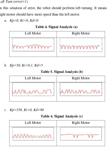
1) Left Turn (error=1)
In this situation of error, the robot should perform left turning. It means that
the right motor should have more speed than the left motor.
a. Kp=0, Ki=0, Kd=0
Table 4. Signal Analysis (a)
Left Motor Right Motor
b. Kp=50, Ki=0.1, Kd=5
Table 5. Signal Analysis (b)
Left Motor Right Motor
c. Kp=556, Ki=0, Kd=90
Table 6. Signal Analysis (c)
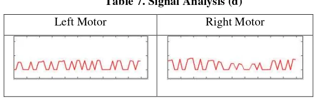
d. Kp=700, Ki=1, Kd=200
Table 7. Signal Analysis (d)
Left Motor Right Motor
2) Right Turn (error=-1)
Our goal in this error value, the robot should perform right turning. So, the left
motor should have more speed than the right motor.
a. Kp=0, Ki=0, Kd=0
Table 8. Signal Analysis (e)
Left Motor Right Motor
b. Kp=50, Ki=0.1, Kd=5
Table 9. Signal Analysis (f)
Left Motor Right Motor
c. Kp=556, Ki=0, Kd=90
Table 10. Signal Analysis (g)
d. Kp=700, Ki=1, Kd=200
Table 11. Signal Analysis (h)
Left Motor Right Motor
From this experiment, we see that only when Kp = 556, Ki = 0 and Kd = 90, the
motor performance is in its best. The duty cycle occurs while turning on both motor
indicates a good combination. When right turning, the duty cycle on left motor should
be higher. Also when left turning, right motor duty cycle should be higher too.
Another combinations that we use in this experiment show that the duty cycles of
both motors are randomly formed. This is why in those combinations, the robot
randomly changes its both motors speed.
3.3 Communication Range
In this experiment, we will test the communication range between the robot and
the android smartphone. Bluetooth signal is used in this project to be a medium signal
of the data transfered from the robot to the android smartphone and vise versa. For
sure, to communicate wirelessly trough bluetooth, there is a range limit of the matter
of distance. General bluetooth device on market, usually has range until around 10
meters. But, we need to prove it if it is true fact or not. In this project we use two
bluetooth, HC-05 Bluetooth for the robot and android smartphone bluetooth.
By conducting this experiment, we can prove that the distance between the robot
and the android smartphone is a real matter. Because it will delay the data transfer. By
this fact, we need to be close enough to the robot if we want to have a good data
transfer. Last, if the distance more than 13 meters, the connection will be lost.
3.4 Analysis
From the first experiment that we did, we can analyze that the robot performance
depends on Kp, Ki and Kd combination. Kp value affects the responsivity of the robot
towards the line. Ki value affects the movement of the robot exponentially. Because
we use the type of robot that has small incremental linear error values, we leave it 0.
Kd value affects the turning performance, in other words, it changes the speed of the
motor while turning.
Duty cycle in a DC motor control is a crucial thing, we can adjust the duty cycle
when we want to increase the speed of the motor by increasing it. And we can
decrease the speed of the motor by decreasing it. So by this logic, a robot can turn
right when the left motor is in higher duty cycle. Also when the robot make a left turn,
so the duty cycle on right motor should be higher. In the second experiment, we can
see what Kp, Ki and Kd affect to the duty cycles of both motors.
4. CONCLUSION
If we see how big the number of possibility of the combination of Kp, Ki and Kd
to determine the best PID value of a system, it is very hard to do it by reprogramming
the robot trough a computer. This way of PID tuning will make all the robot makers
very happy, because they don’t need to bring their laptop or even big personal
computer. Only bringing their robot and a piece of smartphone on pocket while
performing the robot is the best preference.
Building android application with advance programming is a good way. But, for
some engineers, to program an android application is not that easy. MIT
(Massachusetts Institute of Technology) provide us a simple way to build an android
application by their software called App Inventor. For building an android application
based on electronics, they provide us some features that can support our electronic
project. That is way, the writer suggest all electronic engineers who don’t have any
experience in mobile application programming to use it as a tool.
Considering the type of wireless technology to control a system is a need. For this
But, if we design it to control in more distances, we really need to change the medium
using high-level of wireless technology.
ACKNOWLEDGEMENT
I am very thankful to Allah, by His chance, I can finish this final project journal.
Thanks to Mr. Umar, The Head of our Department, who always providing us a good
environment in our department.
Thanks to Mr. Fajar Suryawan, my supervisor, by his guide, I enjoy doing my
final project because of his credebility being a great lecturer. Thanks to my parents
who always push me to do many good things. Thanks to all my friends, 24Ours,
Unerion and UMS colleges who always support me.
REFERENCES
Kurfess, Thomas (2005). Robotics and Automation Handbook.
Alvaro, Victor (2016). Model-Reference Robust Tuning of PID Controllers. Springer
International Publishing.
Boylestad, R. (2003). Introductory Circuit Analysis, Tenth Edition. New York:
Prentice Hall.
Piyare, R. And Tazil, M. (2011) “Bluetooth based home automation system using
Android phones”. IEEE 15TH International Symposium on Consumer Electronics