ELECTRIC VEHICLE POWER OPTIMIZATION STRATEGIES
AMELIA BINTI MD RASID B011010216
Bachelor of Electrical Engineering (Power Electronic And Drives)
“I hereby declare that I have read through this report entitle “Electric Vehicle (EV) Power Optimization Strategies” and found that it has comply the partial fulfillment for awarding the degree of Bachelor of Electrical Engineering (Power Electronics and Drives)
Signature : ……….
Supervisor‟s Name : DR. KASRUL BIN ABDUL KARIM
ELECTRIC VEHICLE (EV) POWER OPTIMIZATION STRATEGIES
AMELIA BINTI MD RASID
A report submitted in partial fulfillment of the requirement for the degree
Faculty of Electrical Engineering
UNIVERSITI TEKNIKAL MALAYSIA MELAKA
I declare that this report entitle “Electric Vehicle (EV) Power Optimization Strategies” is the result of my own research except as cited in the references. The report has not been accepted any degree and is not concurrently submitted in candidature of any other degree.
Signature : ………
Name : AMELIA BINTI MD RASID
ACKNOWLEDGEMENT
First and foremost, I would like to express my gratitude to my supervisor Dr. Kasrul bin Abdul Karim, a lecturer from Faculty of Electrical Engineering for his supervision, support and encouragement towards completion of this project and report.
I also would like to thank my parents En Md Rasid bin Khalid and Pn Norma binti Saad and my beloved family for their moral support throughout completing this project. Not to forget to my entire friend for their endless support, assistance and ideas.
ABSTRACT
ABSTRAK
TABLE OF CONTENTS
LIST OF TABLES ... vii
LIST OF FIGURES ... viii
LIST OF ABBREVIATIONS ... ix
CHAPTER 1 ... 1
INTRODUCTION ... 1
1.1 PROJECT BAKGROUND ... 1
1.2 PROBLEM STATEMENT... 2
1.3 OBJECTIVES ... 2
1.4 SCOPE OF PROJECT ... 2
1.5 REPORT OUTLINE ... 3
2.1 INTRODUCTION TO ELECTRIC VEHICLE ... 4
2.1.1 ELECTRIC VEHICLE COMPONENTS ... 5
2.1.2 ELECTRIC MOTOR AND RATINGS ... 6
2.2 RELATED PREVIOUS WORK ... 7
2.3 SUMMARY OF REVIEW ... 15
CHAPTER 3 ... 16
METHODOLOGY ... 16
3.1 INTRODUCTION ... 16
3.2 METHODOLOGY OF THE PROJECT ... 16
3.2.2 LITERATURE REVIEW ... 18
3.2.3 OBTAIN THE ROADWAY / ELEVATION PROFILE ... 18
3.2.4 CALCULATION ... 27
3.2.5 ANALYSIS OF THE DATA ... 32
3.2.6 DISCUSSION ON THE RESULT AND REPORT WRITING ... 33
CHAPTER 4 ... 34
RESULT AND DISCUSSION ... 34
4.1 RESULT ... 34
4.2 DISCUSSION ... 35
CHAPTER 5 ... 38
5.1 CONCLUSION ... 38
5.2 RECOMMENDATION ... 39
LIST OF TABLES
Table 1: Parameters for power consumption calculation ... 29
Table 2: Condition for Calculation ... 30
Table 3: Condition 1 ... 31
Table 4: Condition 2 ... 31
Table 5: Condition 3 ... 32
Table 6: Condition 4 ... 32
LIST OF FIGURES
Figure 1: An Electric Vehicle System ... 4
Figure 2: Power transmission path in an EV ... 6
Figure 3: Example model of traction chain ... 9
Figure 4: Forces on a Vehicle ... 9
Figure 5: Flowchart of the project ... 17
Figure 6: Google earth application ... 20
Figure 7: Roadway from UTeM to Petronas Twin Tower ... 21
Figure 8: Elevation from UTeM to Petronas Twin Tower ... 22
Figure 9: Add path and new path dialogue box ... 23
Figure 10: New path dialogue box ... 23
Figure 11: New path dialogue box ... 24
Figure 12: Newly drawn path ... 24
Figure 13: Elevation for newly drawn path ... 25
Figure 14: Adding 'place mark' on the path ... 25
Figure 15: Elevation profile ... 27
Figure 16: Elementary forces acting on a vehicle ... 27
LIST OF ABBREVIATIONS
UTeM Universiti Teknikal Malaysia Melaka
EV Electric Vehicle
ICE Internal Combustion Engine
PM particulate matter
HC hydrocarbons
NOX nitrogen oxides
CO carbon monoxide
SO2 sulphur dioxide
EVs Electric Vehicles
BMS battery management system
kW kilowatt
hp horsepower
IC internal combustion
DC direct current
PLUS Projek Lebuhraya Utara Selatan
LIST OF APPENDICES
APPENDIX A SPECIFICATION FOR SAGA BLM 1.3 MANUAL
APPENDIX B EDUCATIONAL ACTIVITIES APPLICATION FORM
CHAPTER 1
INTRODUCTION
1.1 PROJECT BAKGROUND
The environmental concerns, energy challenges and the economical issues have urged the automotive industry to develop a clean and efficient as well as sustainable vehicle for urban transportation. Since then, the automotive industry becomes very proactive in the production of vehicles with an alternative energy to replace the conventional types of vehicles which mostly were driven by the gasoline. As a result, the alternative vehicles like electric vehicle (EV) and hybrid vehicles have been introduced and keep on evolving every day [1].
Recently, EVs have become the focus in research compared to all types of the vehicles. This is because EVs provide the means for a clean, efficient and environmentally friendly urban transportation system since it is powered by alternative energy sources and enabled by high-efficiency electric motor and controller.
1.2 PROBLEM STATEMENT
Nowadays, people are more concern about the environment. The usage of fuel such as petrol and diesel to drive the vehicles is not a good choice since the combustion of the fuel produce a lot of pollutant. These pollutants then lead to the greenhouse effect and cause the increase in the temperature of the earth. Besides, fuel can be categorized as a non-renewable energy and will extinct in the future. Therefore, in order to overcome those problems, EV have been invented as an alternative and attractive solution. However, the EV depends solely on the battery as the main source to drive the vehicle and this battery require much longer time for recharge if compared to filling up a gas tank. Besides, the driver also need an additional way to assist and alert them on how longer does the battery can withstand before it needed to be recharged. Therefore, in this study, the power consumption of the electric car are be calculated and the strategy to optimize the power consumption of the EV are proposed based on the analysis of the factors that affect the power consumption of EV.
1.3 OBJECTIVES
The objectives of this project are:
1. To calculate the power consumption of the EV with given roadway profile 2. To analyze the strategy that can optimize the power consumption of EV 1.4 SCOPE OF PROJECT
implementation of the EV will not be covered in this project.
1.5 REPORT OUTLINE
This report consists of five chapters. Chapter one is “Introduction” part. This chapter discuss about the project background, problem statement, objectives and lastly the scope of the project.
Chapter two is about the “Literature Review”. This chapter describe about the theory of the EV and also the past research or study that have been carried out and published. Besides, this chapter also summarizes the ideas of others that are related to this project.
Chapter three is the “Methodology” section. It includes about the calculation of the power consumption of the EV by using the algorithm only. There is no simulation or hardware implementation involves.
“Results and Discussion” is in chapter four. In this chapter, the results from the calculation are analyzed to know the power consumption of the EV.
CHAPTER 2
LITERATURE REVIEW
2.1 INTRODUCTION TO ELECTRIC VEHICLE
EV is a new technology that has been rapidly developed. This technology gets the attention due to awareness to the environment and the facts that fuel is non-renewable energy and EV is able to curb the pollution problem since it does not have emission of pollutant. Therefore, EV has become the alternative way to overcome those problems.In order to be classified as an EV, the vehicle must have the following features:
1. The energy source is portable and electrochemical or electromechanical in nature 2. Traction effort is supplied only by an electric motor
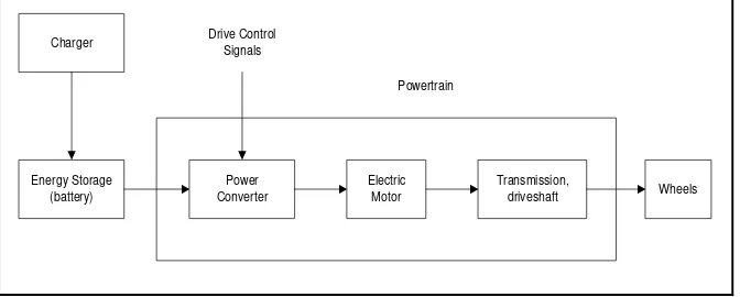
The block diagram of an EV system driven by a portable energy source is shown in Figure 1. The electrochemical energy conversion linkage system between the vehicle energy source and the wheels is the powertrain of the vehicle. The powertrain has electrical as well as mechanical components [3].
Charger Energy Storage (battery) Power Converter Electric Motor Transmission, driveshaft Wheels Drive Control Signals Powertrain
ranging from fossil fuel to solar-based energy. For the battery-based EV, the electric power transmission system is the system required in order for the fuel to be delivered in the form of electricity to the vehicle. As for solar EVs, the solar panel and a power converter is used to charge the batteries on the vehicle. The special feature of these EVs is that these are zero emission vehicles (ZEVs) as far as pollution within the vehicle is concerned [3].
2.1.1 ELECTRIC VEHICLE COMPONENTS
The system for the automobile is very complex. This is due to numerous hardware component and software algorithms interconnected through mechanical links and electrical communications network. The system level design extends to intricate details of subsystem or component design in the automobile design. The system design fundamental includes the physics of motion, energy, power and the energy conversion principle. The primary hardware components for automobile are the energy conversion and the power transmission devices.
Internal combustion (IC) engine, energy storage device and electric machine are the primary energy conversion devices for EV. IC engine is a heat engine that converts chemical energy to mechanical energy. As for electric machine, it can be used either as motor or generator. The electrical energy will be converted as mechanical energy in a motor state and in contrast, the mechanical energy will be converted to electrical energy once it is used as generator.
The drives also can process the electrical power in other way round when the machine operates as generator. In order to convert the high voltage to low voltage levels convert the DC other way round, DC-DC converter is required. This converter can be bidirectional and it is made up from power electronic devices and energy storage inductors. This component is very important and it acts as the key component for the fuel cell interface with electric motor drive.
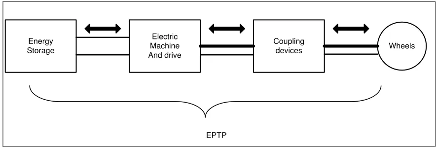
Powertrain is the path for the flow of energy in a vehicle starting from the energy source and ends at the wheels with the deliver propulsion. In EV, the power transmission path is electrical except for the coupling devices between the wheels and electric propulsion motor. This path is known as electric power transmission path as shown in Figure 2. The difference of this path compared to IC energy vehicle is the power and energy flow can be directional. This means that when the vehicle brakes to slow down or stops, the kinetic energy is processed back to energy storage device.
Energy Storage Electric Machine And drive Coupling devices Wheels EPTP
Figure 2: Power transmission path in an EV
2.1.2 ELECTRIC MOTOR AND RATINGS
The types of the motor determines whether maximum torque is availabe at zero speed or not. High torque is available at The peak or rated power from a motor is obtained at base speed (ωb) when the motor characteristics enter the constant power region from constant
torque region once the voltage limit of the power supply is reached.
The motor rated speed (ωrated) is at the end of the constant power region. High torque is
produces by electric motor even at zero speed and typically, it has constant power characteristics over a wide speed range. Because of that, electric motor can be attached directly to the drive wheels to accelerate the vehicle from zero speed to its maximum speed. Therefore, the speed of the vehicle and the motor can be controlled directly through the power electronic converter feeding the current into the motor. Essentially, there is no requirement for a transmission with an electric motor other than a fixed gear for appropriately sizing the motor.
There are several important characteristics of an EV motor. They includes the flexible drive control, fault tolerant, high efficiency and low acoustic noise. Besides, the motor drive also should be able to handle voltage fluctuations from the source.
2.2 RELATED PREVIOUS WORK
Since the vehicle dynamics influenced the energy efficiency, the EV dynamics are taken into account in the research. There are several forces that are included for the vehicle dynamics analysis follows:
Nomenclature:
Fω Road Load
Fro Rolling resistance force
Fsf Stokes‟ force or viscous friction force
Fad Aerodynamic drag force
Fcr Climbing and drag force
Pv Vehicle driving power
Mathematical equation:
Fω = Fro + Fsf + Fad + Fcr (2.1)
where;
Fro= μmg cos α (2.2)
Fsf = kAυ (2.3)
Fad = ½ ξ Cω Af (υ+υo)2 (2.4)
Fcr= ± mg sin α (2.5)
Besides, the formula for the power required to drive a vehicle in the motor ratings and transmission also provided as below:
Pv= υFω (2.6)
performance of EV. High level modeling of electric traction chain is described using VHDL – AMS and it is then simulated using Simplorer 7.0 software.
Figure 3: Example model of traction chain
Besides, in this paper, simple motion equation is derived in order to discuss the ecological driving of an electrical vehicle. In order to maintain the simplicity, acceleration resistance is the only resistance that is taken into consideration. Other resisting forces like rolling, aerodynamics and incline force are neglected. Figure 4 illustrates one wheel model used in order to derive the simple mathematical model of the EV.
Nomenclature:
Frolling Rolling force
Faerod Aerodynamics force
Fgrade Incline force
Pa Power EV must develop at stabilized speed
Pm Power available in the wheels
γ Acceleration of the vehicle (s-2)
T1 Load torque (N.m)
Wm Angular speed of the motor (rad/s)
f Coefficient of rolling friction
Mv Total mass of the vehicle (kg)
g Acceleration of terrestrial gravity (m/s2)
l Density of the air (kg/m3)
S Frontal surface of the vehicle (m2)
Cx Drag coefficient of the vehicle
V Speed of the vehicle (m/s)
α Angle that make the road with the horizontal (in °)
rm Torque gear ratio
Rwheels Wheels radius (m)
Tem Electromagnetic torque of the motor (N.m) Tl Load torque (N.m)
Mathematical model:
Frolling = f x Mv x g (2.7)
Faerod = ½. l.s.cx.V2 (2.8)
Fgrade = Mv.g sinα (2.9)
Pa = V. (Frolling + Faerod + Fgrade) (2.10)
γ = (Pm – Pa/ MvV) (2.12)
γ = [Tem. rm– Rwheels . (FRolling + Faerod + Fgrade)/ Mv. Rwheels] (2.13)
T1 = Rwheels. (FRolling + Faerod + Fgrade) (2.14)
Wm = (rm/Rwheels) . (dγ/dt) (2.15)
EV with high energy efficiency have been develop since fuel consumption has been a key issue in the performance of cars in recent years. However, EV has small battery energy stored. This caused problems related to the running distance per charging, long charging time and many more.
Therefore, Tanaka, Ashida, and Minami have produced a paper concerning “An Analytical Method of Electric Vehicle Velocity Profile Determination from Power Consumption of Electric Vehicles”. In this paper, a method to obtain the performance of the EV from the equations between the measured acceleration, a and the input or the regenerated electric power, P is described analytically. This method is used because it can demonstrate possibilities to predict the performance of EVs using stored electric energy and the driving root [7].
The equations or the mathematical model involved in this analytical are:
Nomenclature:
F Force [N]
Fa Acceleration resistance
Fr Rolling resistance
Fk Air resistance
Ft Inclination resistance
p Output power