UNIVERSITI TEKNIKAL MALAYSIA MELAKA
DEVELOP FUZZY LOGIC TO MONITOR THE HEALTH OF
TRANSFORMER BY USING DGA
This report submitted in accordance with requirement of the Universiti Teknikal Malaysia Melaka (UTeM) for the Bachelor’s Degree in Electrical Engineering
Technology ((Power Industry) with Honours
By
MUHAMMAD ZULHILMI BIN MOHD HANAFI B071110185
900129035153
UNIVERSITI TEKNIKAL MALAYSIA MELAKA
BORANG PENGESAHAN STATUS LAPORAN PROJEK SARJANA MUDA
TAJUK: DEVELOP FUZZY LOGIC TO MONITOR THE HEALTH OF
TRANSFORMER BY USING DGA
SESI PENGAJIAN: 2014/2015 Semester 1
Saya MUHAMMAD ZULHILMI BIN MOHD HANAFI
mengaku membenarkan Laporan PSM ini disimpan di Perpustakaan Universiti Teknikal Malaysia Melaka (UTeM) dengan syarat-syarat kegunaan seperti berikut: 1. Laporan PSM adalah hak milik Universiti Teknikal Malaysia Melaka dan penulis. 2. Perpustakaan Universiti Teknikal Malaysia Melaka dibenarkan membuat salinan
untuk tujuan pengajian sahaja dengan izin penulis.
3. Perpustakaan dibenarkan membuat salinan laporan PSM ini sebagai bahan pertukaran antara institusi pengajian tinggi. atau kepentingan Malaysia sebagaimana yang termaktub dalam AKTA RAHSIA RASMI 1972)
(Mengandungi maklumat TERHAD yang telah ditentukan oleh organisasi/badan di mana penyelidikan dijalankan)
FAKULTI TEKNOLOGI KEJURUTERAAN
PENGKELASAN LAPORAN PSM SEBAGAI SULIT/TERHAD LAPORAN PROJEK SARJANA MUDA TEKNOLOGI KEJURUTERAAN KUASA INDUSTRI (BETI): MUHAMMAD ZULHILMI BIN MOHD HANAFI
Sukacita dimaklumkan bahawa Laporan PSM yang tersebut di atas bertajuk “
DEVELOP FUZZY LOGIC TO MONITOR THE HEALTH OF
TRANSFORMER BY USING DGA
” mohon dikelaskan sebagai *SULIT / TERHAD untuk tempoh LIMA (5) tahun dari tarikh surat ini.2. Hal ini adalah kerana IANYA MERUPAKAN PROJEK YANG DITAJA OLEH SYARIKAT LUAR DAN HASIL KAJIANNYA ADALAH SULIT.
Sekian dimaklumkan. Terima kasih.
Yang benar,
________________
Tandatangan dan Cop Penyelia
* Potong yang tidak berkenaan
NOTA: BORANG INI HANYA DIISI JIKA DIKLASIFIKASIKAN SEBAGAI
SULIT DAN TERHAD. JIKA LAPORAN DIKELASKAN SEBAGAI TIDAK
TERHAD, MAKA BORANG INI TIDAK PERLU DISERTAKAN DALAM
iv | P a g e
DECLARATION
I hereby, declared this report entitled “PSM Title” is the results of my own research except as cited in references.
Signature :
Author’s Name : MUHAMMAD ZULHILMI BIN MOHD HANAFI
v | P a g e
APPROVAL
This report is submitted to the Faculty of Engineering Technology of UTeM as a partial fulfilment of the requirements for the degree of Bachelor of Electrical Engineering Technology (Industrial Power) with Honours. The member of the supervisory committee is as follow:
:
vi | P a g e
ABSTRAK
vii | P a g e
ABSTRACT
viii | P a g e
DEDICATION
ix | P a g e
ACKNOWLEDGEMENT
I would like to thank and express my gratitude for giving me the opportunities and fully support to do my Bachelor Project Degree 1 to UniversitiTeknikal Malaysia Melaka (UTeM).
I will like to express my profound gratitude to En Zulkifli Bin Ibrahim for his supervision, encouragement, suggestions and trusted throughout the duration of this research.
Also I would like to express my big thanks to all my colleagues for their support and time during my research study name. I would like to thank to supportive co-supervisor En Sharil Bin Yahya for supporting in my research material.
xi | P a g e
3.2.1 The Design of Fuzzy Diagnostic 20
3.2.2 Fuzzification 21
3.2.3 Quantization 26
3.2.4 Assignment of Membership Function 27
3.2.5 Fuzzy Rule inference 29
3.2.6 Selection of Fuzzy Compositional Operator 32
3.2.7 Defuzzification 33
3.3 Display Output 33
3.4 Executive summary 35
CHAPTER 4: RESULT AND DISCUSSION 36
4.1 Introduction 36
4.2 DGA data 36
4.2.1 Result for Roger Ratio Method 38
4.2.3 Result for IEC Ratio Method 43
xii | P a g e
5.1 Introduction 57
5.2 Conclusion 57
5.3 Recommendation 59
REFERENCES 60
APPENDICES
A Example of Roger Ratio 61
B Example of IEC method 65
xiii | P a g e
LIST OF TABLES
2.4 Table 2.4: Electrical and Thermal Stresses 8
2.4.2 Table 2.4.2:Oil decomposition 9
2.4.3 Table 2.4.3:Paper decomposition 9
2.4.4 Table 2.4.4:Fault Type 10
2.5.1 Table 2.5.1.1:Roger Ratio 12
2.5.2 Table 2.5.1.2:Roger Ratio 12
2.5.3 Table 2.5.3.1 Doernenburg Method 13
2.5.3 Table 2.5.3.2 Concentration L1 for Doernenburg Method 14
2.5.4 Table 2.5.4 IEC Method 14
3.4 Table 3.4: Roger ratio classification 22
3.5 Table 3.5: IEC method classification 23
3.6 Table 3.6 Key Gases Classification 24
3.8 Table 3.8.1: Roger Ratio quantization 26
3.8 Table 3.8.2: IEC method quantization 27
3.8 Table 3.8.3: Key Gases quantization 27
3.8 Table 3.8.4: Assignment of Membership Function 28
3.8 Table 3.8.5: Roger ratio Rule inference 29
3.8 Table 3.8.5 Roger ratio Rule inference example 29
3.8 Table 3.8.5: IEC ratio Rule inference 30
3.8 Table 3.8.5: IEC ratio Rule inference example 30
3.8 Table 3.8.5: Key Gases ratio Rule inference 31
3.8 Table 3.8.5: Key Gases ratio Rule inference example 31
4.1 Table 4.1: DGA Data 37
4.2 Table 4.2: Roger Ratio Result 39
4.2.1 Table 4.2.1: Roger Ratio Code 40
4.2.2 Table 4.2.2: Classification of fault based on roger ratio codes 40 4.2.3 Table 4.2.3: Actual fault and fuzzy system 41 4.5 Table 4.5: IEC Ratio Code actual and fuzzy fault 44
xiv | P a g e 4.5.3 Table 4.5.3: IEC method actual fault and fuzzy system. 46 4.7 Table 4.7: threshold value for the key gases method 48 4.7.2 Table 4.7.2: Key Gases method actual and fuzzy fault 48 4.7.3 Table 4.7.3: Actual fault and Fuzzy logic system 50
4.7.4 Table 4.7.4: Classification of fault type 51
xv | P a g e
LIST OF FIGURES
2.1 Figure 2.1: Main Transformer under Test 6 2.2 Figure 2.2: Auxiliary Transformer under Test 6
2.3 Figure 2.3: The chemical structure 8
2.6 Figure 2.6.1:Key Gas Method 13
2.5 Figure 2.5.5 Duval Triangle 15
3.1 Figure 3.1: Flowchart of the system 18
3.2 Figure 3.2: Step of Fuzzy logic system 20
3.3 Figure 3.3.1 input and output for Roger ratio method 21 3.3 Figure 3.3.2 input and output for IEC method 23 3.3 Figure 3.3.3 Input and output for Key Gases method 23
3.7 Figure 3.7.1: Roger fuzzy logic toolbox 25
3.7 Figure 3.7.2: IEC fuzzy logic toolbox 25
3.7 Figure 3.7.3: Key Gases fuzzy logic toolbox 25
3.9 Figure 3.9.1: Roger Ratio FIS analysis 34
3.9 Figure 3.9.2: IEC Ratio FIS analysis 34
3.9 Figure 3.9.3: Key Gases Ratio FIS analysis 34
4.1 Figure 4.1: DGA data 38
4.3 Figure 4.3: Actual Fault Roger Ratio pie chart 42 4.4 Figure 4.4: Fuzzy fault Roger Ratio method pie chart 42 4.6 Figure 4.6: Actual Fault IEC method pie chart 46 4.7 Figure 4.7: Fuzzy fault Roger Ratio method pie chart 47
4.8.1 Figure 4.8.1: Result Compare Analysis 54
4.8.1 Figure 4.8.1: Result Compare Analysis 54
4.8.2 Figure 4.8.2: Comparison of accuracy of different method 55
xvi | P a g e
LIST OF ABBREVIATIONS, SYMBOLS AND
NOMENCLATURE
�2 - Hydrogen
��4 - Methane
�2�6 - Ethane
�2�4 - Ethylene
�2�2 - Acetylene
CO - Carbon Monoxide
C 2 - Carbon Dioxide
> - More than
< - Less than
≥ - More than and equal to
≤ - Less than and equal to
RDC - Winding Resistance IR - Insulation Resistance
1 | P a g e
1.0 Introduction
This chapter will describe about the introduction of this project which includes the project background of the whole project, the problem statement that occur before this entire project will be complete. The objectives and scope that are needed to be fulfilled for this project are completely described in this chapter.
1.1 Background
Power transformer is a major component of power system which has no successor for its major role [1]. The transformer, being key element in the transmission and distribution of electrical energy need early attention for its importance. To improve the reliability of the equipment and to avoid any breakdown failure and damage, effective testing and diagnostic techniques must be used [2]. Early detection can reduce damage to the equipment and consequently prevent premature breakdown or failure subsequently lead to huge savings in the operation and maintenance costs and improve the overall system reliability [3]. On the transformers, consequence of electrical and thermal stresses that is detected on the oil
2 | P a g e insulator of the transformer will lead to fault [2-3]. The type of faults that often occur in power transformers are arcing, partial discharge, overheating, sparking, corona and thermal fault at low temperature [1-5].
Transformer oils are combination of many different hydrocarbon molecules. They are composed essentially of saturated hydrocarbon called alkane which general molecular formula is ���2�+2 [4, 6]. The key fault gases produce from electrical and
thermal stresses are hydrogen (�2 , methane (��4), ethane (�2�6), ethylene (�2�4),
acetylene (�2�2), carbon monoxide (CO) and carbon dioxide (C 2) [1-12]. To detect
the type of fault inside the transformer it is by measuring the amount of gases inside the transformer and the gases are produced in transformer oil. Fault is determined by the presence of the gases and severity of the fault indicates on the amount of the gases produced.
There is several type method of test to use to determine the fault gases for transformer oil such as Winding Resistance (Rdc) Test, Insulation Resistance (IR) Test, Tan Delta Test, Transformer Turn Ratio Test, Dissolved Gas Analysis (DGA) test and Dielectric Response Analysis (Dirana) Test [10]. DGA has been known as one of effective and reliable test for the detection of incipient fault condition inside the oil immersed transformer [4]. DGA consist of five techniques which is Key Gas, Rogers Ratio, Doernenburg, IEC Ratio and Duval Triangle [1-12]. Although DGA has been become increasingly effective and reliable, at some point DGA fail to diagnose in some cases because of multiple type fault occurs inside a transformer [3]. This problem happen due to complication of different gases collected and may cause hard to be diagnosed base on the fault type. Fuzzy logic can be introduced to diagnose the problem [3].
3 | P a g e problem and membership function can be adjusted to make a conclusion. In this paper, DGA method is investigate to monitor the health of transformer and fuzzy logic controller was developed to simulate the data obtained.
1.2 Problem Statement
Now, a lot of simulation software for monitor and design especially for power transformer is active at market like SCICOSLAB, PSPICE, Power World, Maxwell and ANSYS. However, this software is not suitable for monitor the health of transformer and develop fuzzy logic program. MATLAB software can be used to determine the incipient fault and at the same time develop fuzzy logic program. Power transformer are the most valuable and important equipment in the operation of modern power system. In this report, by developing fuzzy logic program to compare simulation fault and actual fault present in the transformer it can detect the incipient fault in transformer. Detection of incipient faults can be done using DGA techniques by selecting one of the method that Key gases, Roger Ratio, IEC Ratio, Duval Triangle, and Doernenburg, To get the best method, comparison between the method is taken for the accurate fault condition between simulation fault and the actual fault of the present transformer. Finally, from the simulation fault of the transformer using suggestion method for maintenance and protection the transformer can be proposed in the future.
1.3 Project Objective
The objective of this project is:
1. To compare the result of simulation fault and actual fault present in the transformer.
4 | P a g e 3. Creates some basic construction fuzzy controller block diagrams using
Simulink.
1.4 Scope Of Research
In order to achieve the objectives mentioned above, scope of the project should be highlighted. This project will follow the scope of study as below:
1. Select the best method for determining incipient fault of the transformer based on DGA analysis test. They are: Key Gas, Roger Ratio and IEC Ratio.
5 | P a g e 2.0 Introduction
DGA have become increasingly important in recent year to determine the fault of the transformer. In this section, the literatures give the general view of all of the aspect of this project based on previous method and experiment knowledge to be implemented inside the project.
.
2.1 Transformer testing
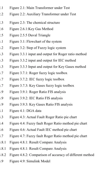
Dadan Nurafiat and Agus Puwardi, (2011) stated that the condition of the transformer can exceed the approximate life using several type of test to diagnose the life of the transformer [8]. Agus Puwardi, (2011) mentioned on this paper that diagnostics basically on the main power transformer and auxiliary power transformer for transformer testing [8]. Below figure 2.1 and figure 2.1, from PT.Indonesia Power Kamojang Geothermal Power Plan the main power transformer and auxiliary power transformer unit 1 [8].
6 | P a g e Figure 2.1: Main Transformer under Test [8]
Figure 2.2: Auxiliary Transformer under Test [8]
2.2 Type Test
There is several type of test that can be conduct for power transformer such as:
7 | P a g e 2.2.2 Winding Resistance (RDC) Test [8]
2.2.3 Insulation Resistance (IR) Test [8]
2.2.4 Tan Delta Test [8]
2.2.5 Dissolved Gas Analysis (DGA) Test [8]
2.2.6 Dielectric Response Analysis (Dirana) Test [8]
2.3 DGA Gas Analysis
Transformer fault is based on different type of gases produced and which lead to different type of fault in transformer, DGA analysis is used to monitor and identify the chemical analysis of these gases [1-4]. In this research project, to obtain dissolve gas in transformer oil DGA gas test is applied [9].In 2011 Dadan Nurafiat studied due to the mixture and increase of gas concentration in oil-immersed power transformer the breakdown and failure of the transformer happen.
2.4 Mechanism Of Gas Generation
In a recent study (Er. Lee WaiMeng, 2009) stated from the hydrocarbon molecules of the mineral oil the essential of gas generation is the decomposition between the chemical bonds interaction. The transformer produced hydrogen (�2 ,
methane (��4), ethane (�2�6), ethylene (�2�4), acetylene (�2�2), carbon monoxide
(CO) and carbon dioxide (C 2) [1-3]. The gases will dissolve in the transformer oil
![Figure 2.1: Main Transformer under Test [8]](https://thumb-ap.123doks.com/thumbv2/123dok/495438.55135/23.595.176.477.72.297/figure-main-transformer-under-test.webp)
