‘I/we admit that have read this work and to me/us this work was adequate from the aspect scope and quality to be honor with Bachelor of Mechanical Engineering
(Structural and Material)’
Signature :………
Supervisor Name :………
DESIGN A FEASIBLE CLOTH DRIER UTILIZING DOMESTIC WASTE-HEAT FOR HOUSEHOLD APPLICATION
MUHAMAD FATHIL BIN MOIN
This thesis is submitted to the faculty of mechanical engineering in partial fulfillment of the partial require for the bachelor of mechanical engineering (Structure and
Material)
Faculty of Mechanical Engineering Universiti Teknikal Malaysia Melaka
“I verify that this report is my own work except for the citation and quotation that the source has been clarified for each one of them”
Signature:………
Author:………....
iii
iv
ACKNOWLEDGMENT
I would like to give appreciation especially to my supervisor, Pn. Fatimah Al-
Zahra Bt. Mohd Sa‟at for supervising me at all the way in conducting the research to fulfill my Projek Sarjana Muda (PSM).
Appreciation is also extended to all lectures, technicians and staffs of
Faculties of Mechanical, Universiti Teknikal Malaysia Melaka.
v
ABSTRACT
This paper is about an experimental study on the effectiveness of using heat emitted from a split-type residential air conditioner (RAC) for clothes drying in residential buildings. This work will focus on utilizing waste-heat from air condition to dry the clothes. In this work a new cabinet for the clothes dryer had been designed
and some of the important formula for drying process had been included. This experiment was done by referring to drying clothes activity and with this project it is
vi
ABSTRAK
Kertas keja ini membincangkan satu kajian terhadap keberkesanan pengunaan haba yang dibebaskan dari penghawa dingin untuk proses pengeringan pakaian bagi kegunaan domestik. Kerja akan tertumpu kepada pengunaan semula haba dari penghawa dingin untuk mengeringkan pakaian. Dalam kertas kerja ini satu reka
bentuk bagi almari untuk mengeringkan pakaian direka dan sebahagian dari rumus yang diperlukan akan diletakan bersama dalam kertas kerja ini agar kajian yang
vii
TABLE OF CONTENTS
CHAPTER ITEM PAGE
VERIFICATION ii
DEDICATION iii
ACKNOWLEDGMENT iv
ABSTRACT v
ABSTRAK vi
TABLE OF CONTENT vii
LIST OF TABLE ix
LIST OF FIGURE x
NOMENCLATURE xi
CHAPTER 1 INTRODUCTION
Introduction 1
1.1Objective 2
1.2 Scope 2
CHAPTER 2 LITERATURES REVIEWS 4
CHAPTER 3 METHODOLOGY
3.1 Design 14
3.2 Material properties 15
3.3 Structural design 20
3.4 Testing and analysis 21
viii
CHAPTER 5 CONCLUSION 36
REFERENCE 38
ix
LIST OF TABLE
NO TITLE PAGE
4.1 weight of the 5 trousers 24
4.2 Experiment data for 5 jean trousers process in dryer cabinet 26
4.3 Experiment data for 5 jean trousers process in natural 27 drying process
4.4 weight of the towel 30
4.5 Experiment data for towel process in dryer cabinet 31
x
LIST OF FIGURE
NO TITLE PAGE
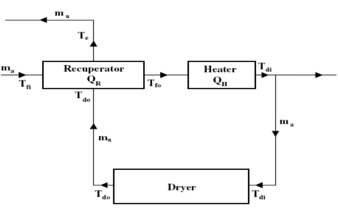
2.1 Diagram of a textile drying system with waste-heat recovery 4
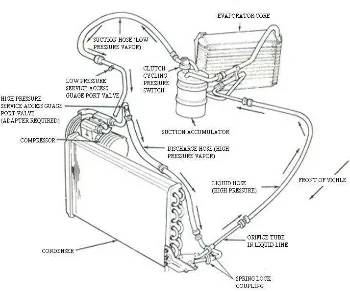
2.2 A simple of RAC systems 8
3.1 View drawing for 3 proposed design 14
3.2 Schematics of the proposed laboratory experimental rig. 20
3.3 Flow chart of the design of drying cabinet 22
4.1 Point of thermocouple in cabinet drier 25
4.2 Graph temperature/Celsius versus time/minute for 5 jeans
trousers in dryer process 28
4.3 Graph humidity/Rh versus time/minute for 5 jean
trousers in dryer process. 29
4.4 Graph temperature/Celsius versus time/minute
for towel dryer process 33
4.5 Graph humidity/Rh versus time/minute for towel
xi
NOMENCLATURE
Cp specific heat capacity (kJ/kg K) Es energy-saving rate (%)
k drying rate (%)
ma rate of process air (kg/h) me rate of evaporated water (kg/h) mpi rate of product-input to dryer (kg)
mpo rate of product-out from dryer (kg) Q actual heat-transfer (kJ)
QH heater capacity (kJ/h)
Qmax maximum possible heat-transfer (kJ)
QR heat of recuperator (kJ/h) QT total heat rate (kJ/h) t drying time (h)
Ta ambient-air temperature (0C) Tdi dryer-inlet air temperature (0C) Tdo dryer-outlet air temperature (0C) Te exhaust-air temperature (0C)
Tfi recuperator-inlet air (fresh-air) temperature (0C) Tfo recuperator-outlet air (fresh-air) temperature (0C) X1 dryer-inlet air_s moisture-content (kgw/kga)
X2 dryer-outlet air_s moisture-content (kgw/kga)
∆X difference of dryer inlet–outlet moisture content (kgw/kga) ∆T difference between Tdo and Te (0C)
ε effectiveness of heat recuperator (%)
xii
ma mass flow-rate of dry air (kg/s) MBD bone-dry mass of clothes (kg) Q heat-flow rate (kW)
Tm mean temperature of the clothes (0C) X moisture content of clothes
ω specific humidity
Subscripts
a air
cold cold fluid hot hot fluid max maximum min minimum w water a air
BD bone-dry mass cl clothes
D drum evap evaporation
0 ambient
CHAPTER 1
INTRODUCTION
Clothes drying, done for ages by the Sun and wind, has become in industrialized societies an important consumer of electrical or other types of energy
through the use of tumbler dryers. In large densely populated cities, residential buildings are usually high-rise blocks. In order to maintain an acceptable appearance of building façade, clothes drying using natural means by hanging clothes outside windows or a balcony may not be allowed. Increasingly, a clothes drying has become confined to indoors, either at the expense of consuming energy through the use of clothes dryers or by natural ventilation. Clothes drying indoors using natural ventilation, versus by an electrical or a gas clothes dryer, can take days, depending on textile type, weather conditions, and the location of a residential flat in a high-rise residential block (e.g., prevailing flat orientation and floor level). In places where air humidity is high (e.g., during wet seasons in end of the year, or during rainy days), clothes drying indoors by natural ventilation can take a long time and still yield unsatisfactory results.
2
Now days in developed countries, the application of residential air conditioning (RAC) has increased and without recycling the consumption of heat from the RAC it can be wasted and to take the advantage of it an innovation had been made to use the recycle heat to make something useful for our daily life. One of the solutions is to prove that the emission of heat is useful in clothes drying process.
Eventually there‟s an alternative method in the drying process using RAC besides the
natural dependence on weather.
The concept of the RAC system for clothes drying had been patented by Shiming Deng in 2004 with the wooden prototype but in this study focuses on an experimental study on the effectiveness of clothes drying using rejected heat (CDURH) with a split-type RAC which will make some improvisations based on
mechanical formula hopefully to be a successful method which will be a benefit to the community.
1.1 OBJECTIVE
The purpose of this project is to design feasible clothes drying apparatus for house hold consumption utilizing waste-heat from air condition. This project also allows us to fully utilize waste heat from domestic appliances for drying purposes.
1.2 SCOPE
3
The theory of the design of clothes dryer was reviewed from various sources such as journals, books, preview reports and the world wide website. Summary of this literature review was presented in Chapter 2. For the design work, it will be divided into 2 parts. The first part is the concept of the design referring to the entire source that had been found. The second part is the sketching/draft of the proposed design. The design will then be constructed and tested for its feasibility and effectiveness.
All the data from the experiment will be collected. The data will be analyzed to obtain the effect of cloth dryer to the air condition/refrigeration that is used in this experiment. Data comparison for each part will be done and the results will be discussed and the result obtained in this research will be compiled and discussed.
4
CHAPTER 2
LITERATURE REVIEW
Drying is the one most energy-intensive operation in the wide range of textile process. The raw material is very humid. The humidity of the fabric is reduced by
[image:17.595.142.477.447.655.2]means of dryers. During drying, the warm moist air is sent to the atmosphere. However, this waste heat should be used in the drying machines. (R. Tugrul Ogulata, 2004)
5
Figure 2.1 shows the drying system with waste-heat recovery studied by R. Tugrul Ogulata (2004). As seen in the Figure above, humid and dirty waste-air from the drying machine is sent to the heat exchanger. Heat transfer via the plate-type heat-exchanger (cross-flow) is realized between the fresh air from the environment and the waste air. While the waste air passes through one channel, the fresh air passes through the abutting channel. Thus, the fresh air temperature is raised and the waste air is cooled and sent to the ambient environment. The temperature of the pre-heated fresh air is further raised in the air heater (R. Tugrul Ogulata, 2004).
Drying clothes indoors by natural ventilation impacts indoor thermal environment, as the moisture contained in wet clothes is transferred to indoor air during drying, by evaporation and diffusion. This additional indoor moisture load
must be dealt with through either mechanical or natural ventilation means. If clothes drying are achieved by either an electrical- or a gas-powered dryer, the drying
process may be completed within hours but at the expense of additional energy use and associated pollution. In an evaporative clothes dryer, air is heated, by either electricity or gas, to a higher temperature (500–700C) and the hot air stream is then used to dry clothes. Hot and humid air that carries away the moisture after passing through clothes is discharged outdoors, contributing to local heat and air pollution.
6
Based upon the literature study, the following basic assumptions are necessary for successful modeling of various processes occurring inside the dryer (V. Yadav, 2008):
• The thermo-physical properties of the fabric material are uniform throughout the volume occupied.
• Dispersion of moisture content within the fabric material is homogeneous.
• Instantaneous distribution of moisture within the working fluid is uniform.
• The temperature of the fabric material and the wet-bulb temperature of the working fluid are the same.
• Instantaneous temperature-distribution within the bulk of the fabric material is uniform.
• Transfer of moisture from the fabric material to the working fluid takes place inside a cylindrical enclosure where the material is placed.
• The cylindrical enclosure and the material being dried may be static or in motion – both cases are considered.
• The hot fluid with low moisture-content enters from one axial direction and leaves via another.
• For the model implementation purpose, all thermo-physical properties of the working fluid are considered to be the same as that of air.
The first step in addressing dehumidification need involves comprehensive system design. (Jung-Ho Huh et.al, 2007) Design and selection of an appropriate heating, ventilating and air-conditioning, HVAC and dehumidification system requires that the system meet both sensible and latent loads. However, since design conditions typically occur at times of high sensible load, off-design conditions often present situations of low sensible load but high latent load. It is necessary to operate the system to match the equipment performance with the building loads over a broad range of off-design operating conditions, while constrained to maintain temperature
7
The equipment capacity SHR is defined as the ratio of the sensible capacity to total capacity, and the load SHR is defined as the ratio of sensible load to total load where the total is the sum of the sensible and latent.
lat sen sen cap CAP CAP CAP SHR (1) lat sen sen load Q Q Q SHR
(2)
Low SHR implies a greater latent fraction and better dehumidification. Under steady-state conditions, energy admass balances dictate that SHRcap = SHRload. Given
a particular system design, the goal of this research is to develop optimal operational strategies for a direct expansion (DX) HVAC system with respect to both energy consumption and thermal comfort. The objective was achieved by applying numerical optimization techniques with a validated simulation model. Optimization techniques have not been widely used in the study of HVAC system operation, and relatively little research on optimal HVAC system operation has been reported in the literature (Jung-Ho Huh et.al, 2007).
Several HVAC systems have been previously studied for optimal control in meeting temperature-cooling requirements only. To date there has been no comprehensive study on the optimal set of HVAC operating parameters for the complete thermal environment. In most applications both temperature and humidity must be maintained, presenting a tougher optimization problem than simple
temperature control. Since providing greater comfort is one of main objectives in
today‟s HVAC industry, the need for efficient active humidity control becomes more
8
Figure 2.2 Simple of RAC systems
Refer to figure 2.2: residential air conditioning is usually by discrete systems, using either window type or split type RACs. Given a choice, a split-type RAC is preferred because of not only its quieter operation but also its flexibility for multi-room services. For a split-type RAC, ambient air is used to carry away heat rejected from its air-cooled condenser, and is therefore heated so that its temperature may increase by up to 10 0 C. ( J.E. Braun,2001)
9
In the research of Shiming Deng (2004), he studies on the effectiveness of CDURH with a split-type RAC. An experimental rig has been set up and extensive experimental work has been carried out. The effectiveness was evaluated based on the comparisons by various drying methods, in terms of required drying duration, energy consumption, under Asia‟s climatic conditions.
The drying-process time had been discussed in detailed by V.Yadav et.al
(2008) in their paper entitled “ Fabric DryingProcess in Domestic Dryer”. According
to their study the order of magnitude for the drying time can be obtained as:
) 10 ( 0 )
( . 4s
m X M t DP BD
(3)
Where ∆ω is the humidity ratio between the dryer inlet and exit.
The order for (∆t)r and (∆t)h are nearly equal and considerably smaller than
(∆t)DP. The temperature and moisture content of the load are to be assumed constant
during a time step ∆t and the heat-and-mass transfer processes during the time step are assumed to be in a steady state: the magnitude of ∆t has to be sufficiently less
than (∆t)ror (∆t)h.
In order to evaluate the rate of change of temperature for the load with time,
the approximate energy balance within the drum (over a time interval ∆t) can be
given as:
.
Qgained due to drum loss +
.
Qsupplied by the heater =
.
Qabsorbed in drum +
.
Qlost due to evaporation (4)
Introducing appropriate expressions for the different terms, we get
t Q T mC t Q t h h
10
On rearranging the terms
t C M C XM C M Q Q h h m T T D p D w p BD cl p BD loss D evap t m t m , , , , . . 3 4 . ,
, ( ) (6)
Where Tm,t and Tm,∆t are the temperature at the time t and t + ∆t, respectively; and
MD is the mass of the drum. Furthermore, Cp,w and Cp,D are the specific-heat values
for water and drum mass, respectively.
Heat is energy transferred between two objects because of a temperature difference between them. Heat always travels from hot to cold. Temperature is a measure of the energy, or heat, of something. It is a property that an object has based on the random motions of the particles in that substance. The faster that the molecules move, the higher the temperature and therefore the more heat transferred to a new object. Therefore, heat transfer is the movement of energy from something with high energy (a hot object) to something with low energy (a cold object). Heat transfer can occur three ways. (H.I. Abu-Mulaweh, 2005)
Conductive heat transfer is the movement of heat through solids or between two solids that are touching. An example of conductive heat transfer is common when cooking on the stovetop. We set the pan on top of the stove. The stove heats the pan at the bottom of the pan, but it is not just the bottom of the pan that gets hot. The handle of the pan often gets hot also. This is because conduction occurs within the pan that transfers the heat from the bottom of the pan, throughout the pan to the handle. In the potato example, heat is conducted from the oven rack that the potato is sitting on, to the potato skin, and again from the outside of the potato to the inner potato. When hot food is placed on a cold plate, heat is transferred via conduction
from the hot food that is touching the plate to the plate. Conductive heat transfer can be represented by a basic equation. Our task is to introduce this equation and dissect it into understandable parts. . (H.I. Abu-Mulaweh, 2005)
11
Heat transfer can be represented by numerous different equations. Convective heat transfer is the movement of heat due to fluid movement. If you were to fill a bathtub full of water and then realize that it was too hot, you would add more cold water. If you can relate to such an instance, you know that the cold water is often at the faucet end of the tub, while the hot water stays at the other end. If you swirl the water around though, it mixes. The hot water transfers heat to the cold water by heat convection due to the swirling. . (H.I. Abu-Mulaweh, 2005)
Q = -hA(Ts– T) (8)
Radiant heat transfer is the transfer of heat from a heated surface. The most common form of radiant heat transfer is the transfer of heat from the sun to the earth.
This is what keeps us warm. We can also see radiant heat transfer while baking a potato in the oven. The oven is heated up and then the heat is transferred radiantly
from the walls of the oven to the potato in the oven. Radiant and convective heat transfer is represented by a similar equation. Our task is to introduce the equation and dissect it into understandable parts. The equation below represents both radiant and convective heat transfer. . (H.I. Abu-Mulaweh, 2005)
Q = -hA(Ts– T) (9)
Mathematical formulation for drying process had been discus by R. Tugrul
Ogulata (2004) in his study of “Utilization of Waste-heat Recovery in Textile
Drying”. In his study, he defined Effectiveness, ε, of the heat exchanger is defined as
the ratio between actual heat-transfer rate and the maximum possible heat-transfer rate from one stream to another.
max Q Q