THE INVESTIGATION OF TURBO-GENERATOR ON EXHAUST MANIFOLD IN SPARK IGNITION ENGINE
ARDIKA RIDAL BIN AWANG
i
SUPERVISOR DECLARATION
“I hereby declare that I have read this thesis and in my opinion this report is sufficient in terms of scope and quality for the award of the degree of Bachelor of
Mechanical Engineering (Thermal-Fluids).”
ii
THE INVESTIGATION OF TURBO GENERATOR ON EXHAUST MANIFOLD IN SPARK IGNITION ENGINE
ARDIKA RIDAL BIN AWANG
This report had been done in partial fulfilment for Bachelor of Mechanical Engineering (Thermal-Fluids)
Faculty of Mechanical Engineering Universiti Teknikal Malaysia Melaka
iii
DECLARATION
“I hereby declare that the work in this report is my own except for summaries and source which have been duly acknowledged.”
iv
This report is dedicated to my family. Thank you for your continuous support during
my vibrant educational years. Without their patience, understanding and most of all
love, the completion of this work would not have been possible.
To my parents,
Awang Bin Bakar and Ruminah Binti Makmum
My siblings
Arzmi Faizal Bin Awang
Arkhariquan Bin Awang
Arthikarina Binti Awang
Arfarica Binti Awang
Arzeekhariha Binti Awang
Ahmad Johari Bin Awang
v
ACKNOWLEDGEMENT
First of all, its grateful to our God Allah S.W.T because with His permission that I can finish this “Project Sarjana Muda” (PSM) to complete the requirement for my graduation on Bachelor of Mechanical Engineering (Thermal-Fluids) in Universiti Teknikal Malaysia Melaka, UTeM. Also, I would like to appreciate to Mr. Safarudin Gazali Herawan, my PSM supervisor who was always helping me through my PSM. With his willingly guidance and words of advice, I manage to complete my PSM in time that for my requirement for my graduation. With his knowledge and experience that is honestly share with me, automatically enhance my knowledge as well as technical skill obtain while completing the tasks that are assigned to me to complete this PSM.
In addition, I would like to express gratitude to my both panel PSM, Mr. Mohd Ruzi Bin Harun and Mr. Abdul Rafeq Bin Saleman that also give an advice and critics about my PSM. From these critics also can develop new ideas to improve my technical skill and to enhance my PSM. Moreover to all technician and lab assistance at Fasa B, UTeM that were involve in this PSM and also guide me to fabricate and also testing some experiment regarding to this PSM and using lab equipment to complete this PSM. Furthermore, to my fellow friends especially my classmate that had been with me since the Semester 1, for they kind and helpful throughout the semester until to final year.
vi
ABSTRACT
vii
ABSTRAK
viii
TABLE OF CONTENT
CHAPTER TITLE PAGE
DECLARATION i
ACKNOWLEDGEMENT v
ABSTRACT vi
ABSTRAK vii
TABLE OF CONTENT viii
LIST OF FIGURES xi
LIST OF TABLES xiv
LIST OF SYMBOLS LIST OF APPENDIX
xv xvi
CHAPTER 1 INTRODUCTION
CHAPTER 2
1.1 Project Background 1.2 Problem Statement 1.3 Objective
1.4 Scope
1.5 Project Significant
LITERATURE REVIEW 2.1 Energy Loses In Vehicle
2.1.1 Engine Losses 2.1.2 Idling Losses 2.1.3 Accessories 2.1.1 Driveline Losses 2.1.1 Aerodynamic Drag 2.1.1 Rolling Resistance
ix
CHAPTER 3
CHAPTER 4
2.1.1 Overcoming Inertia 2.2 Internal Combustion Engine
2.1.1 Four Stroke SI Engine 2.3 Toyota 4A-GE Engine 2.4 Turbocharger
2.5 Generator
METHODOLOGY 3.1 Introduction 3.2 Process Flow
3.3 Turbo-Generator System 3.4 Turbo System
3.4.1 Turbo Modification 3.4.2 Turbo Casing 3.4.3 Turbo Installation 3.5 Generator System 3.5.1 Generator Selection 3.5.2 Generator Modification 3.5.3 Generator Installation 3.6 Experimental Setup
3.6.1 Speed Measurement 3.6.2 Pressure Measurement 3.6.3 Temperature Measurement 3.6.4 Generator Measurement 3.6.5 Throttle Angle Measurement 3.6.6 Intake Measurement
3.6.7 Data Logger Installation 3.6.8 Software Installation 3.6.9 Experiment Method
RESULT AND DISCUSSION 4.1 Introduction
4.2 Non Turbo-Generator Experiment
x
CHAPTER 5
4.3 With Turbo-Generator Experiment 4.3.1 Problem Encounter
4.3.1 Result
CONCLUSION AND RECOMMENDATION 5.1 Conclusion
5.2 Recommendation 5.2.1 Pressure Sensor 5.2.2 Wiring
5.2.3 Coupling
5.2.4 Future Research
REFERENCES APPENDICES
44 44 49
53 54 54 54 54 55
xi
LIST OF FIGURES
NO. TITLE PAGE
2.1 Energy Loses Occurs In Vehicle 4
2.2 Process For Ice 8
2.3 Toyota 4A-GE 1st Edition Engine 9
2.4 Toyota 4A-GE Valve Angle 10
2.5 Turbocharger Versus Normal Aspirated 11
2.6 Turbocharger Diagram 11
3.1 Process Flow Chart For Methodology 15
3.2 Turbo Generator System 16
3.3 Normal Turbocharger System That Had Being Disassembled.
14
3.4 Compressor Had Being Removed From The Turbine. 17
3.5 Turbo And Casing Installation. 17
3.6 Several Of Motor To Be Selected As Generator. 19
3.7 Several Of Motor Were Damage And Cannot Be Use Anymore
19
3.8 Drilling Equipment As Mechanical Energy Source. 20
3.9 Torque Measurement Device. 20
3.10 Voltage / Speed / Amp Measurement. 21
3.11 Light Bulb As Electrical Load. 21
3.12
Before Modification Of Gear Ratio On The Left And After The Modification On The Right Side Of The Figure.
22
3.13
The Upper Case Of The Gearbox Being Cut By The Milling Machine In Machines Workshop At Fasa B, FKM UTeM.
xii
[image:13.595.125.510.39.767.2]3.14 A Plate That Can Be Replaced The Upper Case Of The Gearbox After The Modification Of The Gearbox On Figure 3.9.
22
3.15 Bearing Holder That Had Been Welded To The Generator.
23
3.16 Placement Of The Modified Generator. 23 3.17 Tachometer Installed For Engine Speed Measurement. 25 3.18 Tachometer Installed For Vehicle Speed. 26 3.19 Tachometer installed for turbine speed measurement. 26 3.20 Pressure Gauge To Measure Pressure. 27 3.21 Pressure Transducer To Measure Pressure. 28 3.22 Valve Angle To Measure Throttle Angle. 29
3.23 Pitot Tube On The Air Intake. 30
3.24 Daisy Data Logger. 31
3.25 Picolog Data Logger. 32
3.26 Proskit Data Logger (Left) And Extect Data Logger (Right).
32
3.27 Daisylab 10.0 Interface Software. 33
3.28 Extech Interface Software. 34
3.29 Picolog Interface Software. 34
3.30 Proskit Interface Software. 34
3.31 Test track on Melaka Autocity. 35 4.1 Graph of Trottle Angle & Flowrate against Time. 38 4.2 Graph of Flowrate & Velocity against Time. 39
4.3 Graph of Flowrate & Pressure against Time. 39 4.4 Graph of Flowrate & Temperature against Time. 40 4.5 Graph of Flowrate & Engine Speed against Time. 41 4.6 Graph of Engine Speed & Vehicle Speed against Time. 41 4.7 Graph Of Engine Speed & Pressure BT Against Time. 42 4.8 Graph Of Temperature & Pressure BT Against Time. 43
4.9 Pressure Transducer. 45
4.10 New Pressure Sensor. 46
xiii
4.12 Graph of Pressure against Voltage. 47 4.13 New pressure sensor installed at the vehicle. 48
4.14 Working Space. 48
4.15 Wrecked coupling. 49
xiv
LIST OF TABLES
NO. TITLE PAGE
3.1 List Of Parameters. 27
xv
LIST OF SYMBOLS
RPM = Revolution per Minute N = Engine Speed (rev/s)
V = Voltage (V)
oC = Temperature, Celcius
o = Degree
T = Torque (N.m)
W = Power (watt)
P = Pressure (Pascal) Bar = Pressure (Bar)
xvi
LIST OF APPENDIX
D Turbo – Generator Experiment Data Result 68
APPENDIX TITLE PAGE
A Drawing For Shaft. 57
B Drawing For Gearbox 57
1
CHAPTER I
INTRODUCTION
1.1 PROJECT BACKGROUND
2
1.2 PROBLEM STATEMENT
Generally, vehicle energy supply by fossil fuel such as petroleum and diesel. Unfortunately, almost 90% energy supply from the fossil fuel were wasted throughout the process starting from combustion process in the engine through the exhaust system of the vehicle. This wasted energy should be recover such as to generate other kind of energy for example electrical energy. Turbocharger is an energy recovery system that had been develop, it uses waste energy from the exhaust gas that produce by the combustion process. The exhaust gas flown to the turbine shaft and rotate the compressor then increase the volume of air intake into the combustion chamber, thus producing more power to the engine performance. However, it also decreases the lifespan of engine for example over-boosting and engine knocking. Therefore, the turbocharger can also be uses for other application by converting mechanical energy to electrical energy.
1.3 OBJECTIVE
In this investigation, several objectives are focused such as:
1. To investigate the effect of Turbo-Generator system to the vehicle performance.
2. To determine how much the Turbo-Generator system can produce electrical energy on a vehicle.
1.4 SCOPE
3
1.5 PROJECT SIGNIFICANT
4
CHAPTER II
LITERATURE REVIEW
2.1 ENERGY LOSES IN VEHICLE
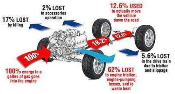
[image:21.595.171.472.392.555.2]When fuel supply to the tank and through internal combustion engine (ICE), it transform an enormous energy by chemical reaction occurs in ICE. The only energy use to travels the vehicle is only 12.6% from the fuel supply (Dario, V. 2009). The other energy some are use and also wasted as shown in Figure 2.1.
Figure 2.1: Energy loses occurs in vehicle. (Source : www.consumerenergycenter.org)
5
accessories and operation of the vehicle 3 of these type of loses (Friction, Mechanical load, Heat and noise) can be specific as about the fraction of the energy loses are describe in their process and operation (Dario, V. 2009).
2.1.1 Engine Losses – 62.4%.
In fossil fuel powered vehicles either using petroleum or diesel, over 62% of the fuel’s energy is lost in the internal combustion engine (ICE). ICE engines are very ineffective at converting the fuel’s chemical energy to mechanical energy, losing energy to engine friction, pumping air into and out of the engine, and wasted heat. More significantly, thermal energy are the most loses occurs such as in radiator and exhaust heat as high as 55% of total engine losses (Oliver, I. 2012). Progressive engine equipment such as variable valve timing and lift, cylinder deactivation, direct fuel injection, and turbo charging can be used to decrease these energy losses.
2.1.2 Idling Losses – 17.2%.
In metropolis driving, significant energy is lost to idling at stop lights or in traffic. Technologies such as integrated starter systems help reduce these losses by automatically turning the engine off when the vehicle comes to a halt and resuming it immediately when the accelerator is pressed (Oliver, I. 2012).
2.1.3 Accessories – 2.2%.
6
2.1.4 Driveline Losses – 5.6%.
Energy is lost in the transmission and other parts of the driveline as gear rotation and other rotational equipment on the vehicle. Technologies, such as automated manual transmission and continuously variable transmission, are being developed to reduce these losses (Oliver, I. 2012).
2.1.5 Aerodynamic Drag – 2.6%.
A vehicle must consume energy to travel air out of the way as it drives down the road, less energy at lower speeds and progressively more as speed increases (Oliver, I. 2012). Drag is in a straight line related to the vehicle’s shape. Smoother vehicle forms have already reduced drag significantly, but additional reductions of 20-30% are acceptable.
2.1.6 Rolling Resistance – 4.2%
Rolling resistance is an amount of the force needed to travel the tire frontward and is directly proportional to the weight of the load sustained by the tire. A variation of new technologies can be castoff to decrease rolling resistance, as well as improved tire tread and shoulder designs and materials used in the tire belt and traction surfaces. For passenger cars, a 5-7% decrease in rolling resistance intensifications fuel efficiency by 1% (Oliver, I. 2012). However, these developments must be balanced in contradiction of traction, durability, and noise.
2.1.7 Overcoming Inertia; Braking Losses – 5.8%
7
technologies (e.g., automated manual transmissions weigh less than conventional automatics). In addition, any time use brakes, energy initially used to overcome inertia is lost.
2.2 INTERNAL COMBUSTION ENGINE
An internal combustion engine (ICE) is an engine that runs by burning its fuel inside the engine. The most common internal combustion engine type is gasoline powered that is includes fueled by diesel, hydrogen, methane, propane, etc. Engines characteristically can singly run on one kind of fuel and involve adaptations to regulate the air/fuel ratio or mix (Ganesan, V.2002).
In a gasoline or petrol engine, a mixture of gasoline and air is sprayed into a cylinder by nozzle. Mixture is compressed by a piston and at optimal point in the high compression stroke. A spark plug in the valve creates an electrical spark that ignites the fuel. The combustion of the fuel consequences in the generation of heat, and the hot gases produced that are in the cylinder are then at a higher pressure than the fuel-air mixture and so drive the piston back down. These combustion gases are emitted and the fuel-air mixture reinstated to course a second stroke. The lined motion of the piston is generally connected by a crankshaft to create circular motion. Valves control the intake of air-fuel mixture and permit exhaust gasses to exit at the right times.