SMART CAGE SYSTEM
NANTHAKUMAR A/L MUNISAMY
This report is submitted in partial fulfillment of the requirements for the award of Bachelor of Electronic Engineering (Telecommunication Engineering)
With Honours
Faculty of Electronic and Computer Engineering Universiti Teknikal Malaysia Melaka
BORANG PENGESAHAN STATUS LAPORAN PROJEK SARJANA MUDA II
Tajuk Projek : SMART CAGE SYSTEM
Sesi
Pengajian : 2009/2010
Saya NANTHAKUMAR A/L MUNISAMY
mengaku membenarkan Laporan Projek Sarjana Muda ini disimpan di Perpustakaan dengan syarat-syarat kegunaan seperti berikut:
1. Laporan adalah hakmilik Universiti Teknikal Malaysia Melaka.
2. Perpustakaan dibenarkan membuat salinan untuk tujuan pengajian sahaja.
3. Perpustakaan dibenarkan membuat salinan laporan ini sebagai bahan pertukaran antara institusi
pengajian tinggi.
4. Sila tandakan ( √ ) :
SULIT*
(Mengandungi maklumat yang berdarjah keselamatan atau kepentingan Malaysia seperti yang termaktub di dalam AKTA RAHSIA RASMI 1972)
TERHAD* (Mengandungi maklumat terhad yang telah ditentukan oleh
organisasi/badan di mana penyelidikan dijalankan)
TIDAK TERHAD
Disahkan oleh:
__________________________ ___________________________________
(TANDATANGAN PENULIS) (COP DAN TANDATANGAN
PENYELIA)
Alamat Tetap : NO 56, TAMAN SERI INDAH, 32400 AYER TAWAR, PERAK.
“I, hereby declare that this thesis entitled, Smart Cage System is a result of my own research idea concept for works that have been cited clearly in the references.”
SIGNATURE: ………
“I, hereby declare that I have read this report an in my opinion this report is sufficient
in terms of scope and quality for the award of Bachelor of Electronic Engineering (Telecommunication Engineering) With Honours”
Dedicated to:
ACKNOWLEDGEMENT
I would like to take this opportunity to express my most sincere gratitude to my project supervisor, Mr. David Yap Fook Weng for accepting me as his project student and providing me excellent guidance, concern, informative support and editorial advice in preparation of this project. In fact, he gave me guidance when obstacles arise throughout this period of time. Once again, thanks to him for his tolerance and endeavors.
ABSTRAK
ABSTRACT
LIST OF FIGURE
NO TITLE PAGE
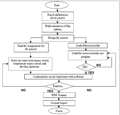
1.1 Flow Chart of Methodology 5
2.1 Open loop control system 8
2.2 Closed Loop Control System 9
2.3 Input Devices 10
2.4 Output Devices 11
2.5 Thermistor 12
2.6 Construction of RTD 13
2.7 Bridge Circuit 14
2.8 Thermocouple 14
2.9 Reference-junction circuit 15
2.10 Magnetic relay 17
2.11 Solenoid Valve 20
2.12 Pin Configuration of AT89S51 Microcontroller 22
2.13 Block Diagram of AT89S51 Microcontroller 22
2.14 Pin Configuration of Microcontroller 68000. 23
2.15 The design cycle 24
2.16 Flash Workplace 28
2.17 Components of Timeline 29
2.18 Keyframe 30
2.19 Action Script 31
3.1 Flow chart of project methodology 34
3.2 Circuit route part on Plastic transparent. 36
3.3 Removing Tape cover of the PCB 37
3.6 PCB board from MEGA 38
3.7 Drill bits 39
3.8 PCB board drilling 39
3.9 Soldering 40
4.1 Design of smart cage system 44
4.2 Microcontroller AT89S51 47
4.3 Microcontroller AT89S51 circuit 47
4.4 Power supply 48
4.5 Power supply circuit 48
4.6 Temperature sensor 49
4.7 Temperature sensor circuit 49
4.8 Water level sensor 50
4.9 Water level sensor circuit 51
4.10 Flow chart of RF Transmitter 52
4.11 Radio Frequency Transmitter 53
4.12 Radio Frequency Transmitter circuit 53
4.13 Flow chart of RF Receiver 54
4.14 Radio Frequency Receiver 55
4.15 Radio Frequency Receiver circuit 55
LIST OF TABLES
LIST OF APPENDIX
NO TITLE PAGE
2.1 Comparison of Control system 9
2.2 Comparison of the Temperature Sensors 16
4.1 Rising temperature versus time 45
NO TITLE PAGE
CHAPTER CONTENT PAGE
PROJECT TITLE i
REPORT STATUS VERIFICATION FORM ii
STUDENT‟S DECLARATION iii
SUPERVISOR‟S DECLARATION iv
DEDICATION v
ACKNOWLEDGEMENT vi
ABSTRAK vii
ABSTRACT viii
LIST OF FIGURES ix
LIST OF TABLES xi
LIST OF APPENDICES xi
I INTRODUCTION
1.1 Introduction 1
1.2 Background of Project 2
1.3 Objectives of Project 2
1.4 Problem Statement 3
1.5 Scopes of Work 3
1.6 Research Methodologies 4
1.7 Thesis Outline 6
II LITERATURE REVIEW
2.1 Introduction 7
2.2 Control System 7
2.2.2 Closed Loop Control System 8 2.2.3 Comparison of Control System 9
2.3 Input Devices 10
2.4 Output Devices 10
2.5 Temperature Sensor 11
2.5.1 Thermistor 11
2.5.2 RTD 12
2.5.3 Thermocouple 14
2.5.4 Comparison of the Temperature Sensors 16
2.6 Relay 16
2.6.1 Latching relay 17
2.6.2 Reed relay 18
2.6.3 Contactor relay 18
2.6.4 Buchholz relay 18
2.6.5 Overload protection relay 19
2.7 Water Level Sensor 19
2.8 Solenoid Valve 19
2.9 Microcontroller AT89S51 21
2.10 Microcontroller 68000 23
2.11 MPLAB IDE 23
2.12 Adobe FLASH CS3 27
2.12.1 FLASH Interface 27
2.12.2 Animation In Flash CS3 28
III PROJECT METHODOLOGY
3.1 Introduction 32
3.2 Project Methodology Workflow 32
3.3 Animation Development 35
3.4 Software Development 35
3.5.2 PCB Drilling Process 39
3.6 The Gantt chart 41
IV RESULT AND ANALYSIS
4.1 Introduction 43
4.2 Result 43
4.2.1 Animation by Flash software 44
4.2.2 Rising time analysis 44
4.3 Circuit description 45
4.3.1 Microcontroller AT89S51 circuit 45
4.3.2 Power Supply Circuit 48
4.3.3 Temperature sensor circuit 49
4.3.4 Water Level Sensor 50
4.3.5 Radio Frequency (RF) Transmitter 51 4.3.6 Radio Frequency (RF) Receiver 53
4.3.7 Relay circuit 55
V DISCUSSION AND CONCLUSION
5.1 Discussion 57
5.2 Improvement and suggestion 59
CHAPTER 1
INTRODUCTION
1.1Introduction
Smart cage system is a system to ensure pets can survive even if there no one at home. Smart cage system will alert owner when food level & water level inside cage low and unstabilized temperature level inside cage. This system used to control food level, water level and temperature level in the cage.
Water level controller and food level controller are used to keep the water and food in certain level inside a bowl. When the water or foods level inside bowl is low, the signal will send to owner automatically. The temperature controller is used for make sure that the temperature level inside the cage in stable. The suitable temperature for pets (chicken)
is between 29˚c to 35˚c. When the temperature inside cage is hot (>35˚c), the fan will turn on automatically and if the temperature is cold (<29˚c), the heater will turn on automatically.
Microcontroller is a controller that widely used in controlling process. Microcontroller used to control the devices by receiving the input signals, processing the input signals and sending the output signals. Food, water and temperature level are controlled by
microcontroller in smart cage system.
This project is to develop a control system that will keep the water & food in certain level inside a bowl and keep the temperature level in stable. Water level sensor is a device that used to detect the level of liquid within a tank and weight sensor is used for detect food level inside bowl. Temperature sensor is used to detect the range of the temperature inside cage. Signal from water level sensor, weight sensor and temperature sensor will be send to the microcontroller by using Radio Frequency Transmitter. RF Receiver will receive the signal and send to microcontroller. Then, the microcontroller processing the input signals and sending the output signals to owner. These processes operate based on open loop system.
Microcontroller AT89S51 acts as a main part in this project as it triggers and controls the whole circuit. Process of controlling the water level, temperature and foods level will be controlled by Microcontroller. Closed loop system is used as it has a feedback that can trigger any error or disturbance and thus making the temperature inside cage stable and level of the water in the bowl that is required. The task to be performed is to study literature, design, build, and test. The animation of this system is developed by using Flash software. This project can be implemented in the industry area.
1.3 Objectives of Project
Following are the objectives set in this project:
i) To design a circuit that control the temperature, water level and food level inside cage.
ii) To alert owner once water and food level is low inside smart cage system. iii) To develop the model of the control system based on the Microcontroller. iv) For get some literature review about control system that involve in this project like sensor, valve, microcontroller and Flash software.
1.4 Problem Statement
i) Temperature inside cage that not stabilized or uncontrolled brings lot of problem to the animals. Weather factor and other disturbance can easily change the actual temperature that is required and its will affect the animals health. ii) Owner has to bring the pets along whenever the person goes out.
iii) Frequently owner has to check foods and water level inside cage manually. iv) Time consuming for owner.
v) Affect the pet‟s health when the people forget to provide food and water.
1.5 Scopes of Work
The smart cage system builds by using microcontroller as a main component. Microcontroller used to control the all part in this project. Microcontroller receives the signals from sensors like temperature sensor, water level sensor and weight sensor and sends output signals to control the output of the project. With this system the water and food inside bowl and temperature can controlled and maintained. The procedures and methods used to achieve the project objectives are:
a) Literature review and background study
Water level, temperature and weight sensor Microcontroller
Radio Frequency Transmitter and Receiver FLASH software
b) Studying and develop animation of the project with software FLASH Software used to develop the animation
c) Build temperature sensor circuit, water level sensor circuit, power supply circuit, relay circuit and weight sensor.
d) Studying and handling the microcontroller to control the whole project Studying Microcontroller system
Studying and develop Microcontroller program
e) Combine the hardware components with software system which is microcontroller f) Field testing
g) Thesis writing
This report divided into several chapters which are Introduction, Background and Literature Review, Theory, Project Methodology, Result and Analysis and Conclusion. Each chapter begins with identifiable objectives and brief overview.
First chapter is an introduction to the project. It consists of objectives, scope of works, problem statements and research methodologies that clearly describe what is the project is all about.
The second and third chapter contains about theory and concept of the entire project. Literature review based on technologies and information has been done in order to create a specific research about this project. Several research are been highlighted such as sensors, RF Transmitter & Receiver, microcontroller and used Flash software as an animation of the project.
CHAPTER II
LITERATURE REVIEW
2.1 Introduction
This chapter explains literature review based on current and exist technologies and information has been done in order to create a specific research about this project. Research hypothesis is been described clearly. From literature review, there will be an analysis regarding the advantages and disadvantages for each phase of this project.
2.2 Control System
Control system is a set of devices that control, manage or command other devices. Control system operates in logical and natural basic process. Before the automatic control system introduced, there were manual control system used to control the process. Manual control system regarded to the human aided control system. Humans are placed to
monitor and control the system through observe the set points.
closed loop control system. [1] [2]
2.2.1 Open Loop Control System
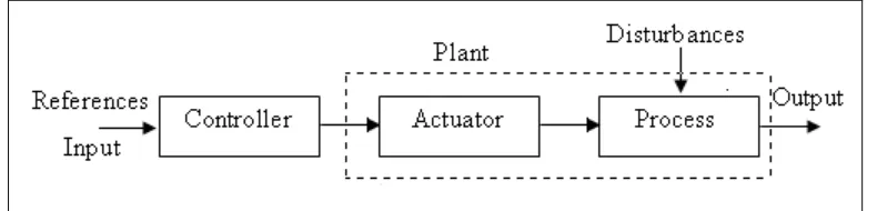
In the open loop system, there are no feedback signals applied to control the system. Error in the system will not be measured and the measured error will not be adjusted to control the input of the system. Bread toaster, water heater kettle are the some of the open loop application system applied product. Open loop control system is easy to apply.
While disadvantage of this system is can‟t trigger the input of the system by measuring
[image:22.612.110.505.362.457.2]the error from output. Figure 2.1 below show the open loop control system block diagram.
Figure 2.1 Open loop control system
2.2.2 Closed Loop Control System
produced desire output even disturbance or error produce due to the process. Figure 2.2 show the block diagram of the closed loop control system.
Figure 2.2 Closed Loop Control System
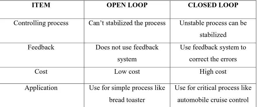
2.2.3 Comparison of Control System
ITEM OPEN LOOP CLOSED LOOP
Controlling process Can‟t stabilized the process Unstable process can be stabilized
Feedback Does not use feedback system
Use feedback system to correct the errors
Cost Low cost High cost
Application Use for simple process like bread toaster
Use for critical process like automobile cruise control
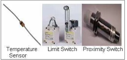
[image:23.612.88.529.415.600.2]Input devices are function as to send the signals which detected from process to the Microprocessor. Sensor is an input device to determine the pressure, liquid level,
temperature and so on. Proximity switch, level sensor, temperature sensor are included in this specific automatic sensing devices.
Some sensors can‟t connect directly to the Microprocessor, because these sensors
[image:24.612.179.436.320.441.2]can‟t generate enough level of signals such as voltage or current. There will be some additional circuit used to amplify the signals from the sensors before connected to the Microprocessor.[2] Figure 2.3 shows some input devices.
Figure 2.3 Input Devices