Wang Tong*1, Guan Yin2, Xu He3, Liang Qiong-chong 4
1,2
Information and Communication Engineering Department,Harbin Engineering University Nantong Street No.145 Harbin China
3
Deparrtment of Mechanics and Electrics Engineering, Harbin Engineering University
4The Fifth Electronics Research Institute of Ministry of Information Industry, China
e-mail: [email protected]*1, [email protected], [email protected], [email protected]
Abstrak
Sistem lingkungan dan getaran uji dapat menguji peralatan seperti radar dalam kondisi beban penuh. Kabin lingkungan dan getaran adalah rongga persegi terbuka. Untuk mempelajari distribusi medan kabin lingkungan dan getaran, distribusi medan rongga terbuka persegi panjang dan antena parabola dianalisis dengan menggunakan fungsi Green Dyadic. Menurut fungsi Green Dyadic, distribusi medan kabin lingkungan dan getaran disimpulkan oleh MATLAB. Hasil simulasi FEKO membuktikan bahwa metode dengan menggunakan fungsi Green Dyadic tersedia. Inovasi dari makalah ini adalah dengan menggunakan fungsi Green Dyadic untuk analisis medan rongga terbuka dan antena parabola.
Kata kunci: FEKO, fungsi Green Dyadic, kabin lingkungan dan getaran, MATLAB
Abstract
Environment and vibration test system can test equipment such as radars in full load condition. Environment and vibration chamber is an opening rectangular cavity. In order to study the field distribution of environment and vibration chamber, the open rectangular cavity field distribution and parabolic antenna are analyzed by using the Dyadic Green’s functions. According to the Dyadic Green’s functions, the field distribution of environment and vibration chamber is concluded by MATLAB. The simulation result of FEKO proves that the method by using Dyadic Green’s functions is available. The innovation of this article is using the Dyadic Green’s functions to analyzed open cavity field and parabolic antenna.
Key worlds: Dyadic Green’s functions, environment and vibration chamber, FEKO, MATLAB
1. Introduction
Environment and vibration test system can test equipment under test such as radars in full load condition. The system includes environment and vibration chamber and microwave chamber. The system could overall accurately reflect equipment under test such as radars performance in high temperature, high humidity and strong vibration environment, could still find temporary failure of equipment under test. But in the experimental process find that the microwave of leakage strengthened because of multiple reflections in metal environment and vibration chamber, the energy is strong enough to influence radars performance, or even damage radars. Excessive leakage microwave could affect the accuracy of equipment under test, so field distribution of environment and vibration chamber are analyzed to find the solution. In recent years, due to the reverberation chamber in the application of electromagnetic compatibility [1], the field distribution of rectangular cavity is mostly analyzed by Dyadic Green’s functions [1, 2]. However, related researches of field distribution of open rectangular cavity were rare. In reverberation chamber study, generally use line antennas as source, and then source can be simplified for current source [3]. Few people involved in researches of parabolic antenna in rectangular cavity. In this paper, open rectangular cavity and parabolic antennas of rectangular cavity was discussed. And prove the correctness of this method in this paper with the test results.
2. Dyadic Green’s Functions in Rectangular Cavity
Figure 1. Structure of environment and vibration chamber
Figure 2. Structure of rectangular cavity
Figure 3. Structure of open rectangular cavity
In Figure 1, the circular in the chamber is parabolic antenna of equipment under test. The front opening of the chamber is facing microwave chamber, size as shown in Figure 1. Environment and vibration chamber is integrated the temperature, humidity and vibration three functions. In the chamber, temperature and humidity can be controlled. At the same time interior also contains a vibration test bench that could simulate vibration condition of the airborne radar in operation process. From Figure 1, environment and vibration chamber is a front opening rectangular cavity.
Figure 2 is completely closed rectangular cavity. Elliptic area is current source. Establish coordinate system as shown in Figure 2, l, a, b are chamber length, width and height.
Make the wave equation into the green functions form [4,5], that is
2
( ,
')-
( ,
')
(
')
e e
G
k
I
δ
∇×∇×
R R
G R R
=
R
−
R
. The pure conductor of the rectangular cavityboundary conditions is
n G
$
×
e( ,
R R
')
=
0
(in the border, that isx
=
0,
x
=
a
andy
=
0,
y
=
b
and
z
=
0,
z
=
l
). And then get Dyadic Green’s functions in rectangular chamber [6,7]:2 0 2 ,
'
' '
0 2 ,
'
' '
1 ˆˆ
( , ') ( ')
2 (2 )
sin
[ ( ) ' ( )
( ) ' ( )] ( )
2 (2 )
sin
[ ( ) ' ( )
( ) ' ( )] ( ) e
m n c g g
eo eo
oe oe
m n c g g
eo eo
oe oe
G zz
k
ab k k k l
l z z
l z z z z
ab k k k l
z l z
z l z z z
δ
δ
δ
= − −
−
−
− − >
+
−
−
− − <
∑
∑
R R R R
M M
N N
M M
N N
(1)
where:
(
)= sin
(
)
( )
g
eo g e g
jk l eo
l
z
k l
k
e
z
−
−
M
M
M
(
)
1
( )
[
(
)
(
)]
2
oe
z
=
o−
k
g+
ok
gN
N
N
(5)ˆ
ˆ
(
)
(
)
jk zge
k
g= −
k C S x
y x y+
k S C y e
x x yM
(6)2
1
ˆ
(
)
(
ˆ
ˆ)
go g g x x y
jk z
g y x y c x y
k
jk k C S x
k
jk k S C y
k S S z e
=
+
+
N
(7)
ˆ
x
、y
ˆ
、z
ˆ
are respectively for unit vector on the direction of x、 、y z,k
xm
a
π
=
;y
n
k
b
π
=
;S
x=
sin
k x
x ;S
y=
sin
k y
y ;C
x=
cos
k x
x ;C
y=
cos
k y
y ;k
2=
k
x2+ +
k
y2k
g2;2 2 2
c x y
k
=
k
+
k
;δ
0 is Kronecker delta. Whenm
=
0
orn
=
0
,δ
0=1
. Whenm
≠
0
andn
≠
0
,0
=0
δ
[7].Eq. (1) to Eq. (7) gives active rectangular cavity in Dyadic Green’s functions. The relationship of field strength and
G R R
e( ,
')
will be discussed in this paper. With the relation between them,electric field strength can be obtained.
3. Dyadic Green’s Functions in Open Rectangular Cavity
The structure of the open rectangular cavity as shown in Figure 3, establish coordinate system as shown.
In general, using Maxwell’s equations in an active area, the Dyadic Green’s function of electromagnetic wave equation is:
2
( ,
')-
( ,
')
(
')
e e
G
k G
I
δ
∇ × ∇ ×
=
−
R R
R R
R
R
(8)
Where:
k
=
2 /
π λ
is wave number. Using the second vector-Dyadic Green’s theorem:[ ( ) ]
ˆ [ ( ) ]
V
S
Q Q dV
n Q Q dS
∇×∇× − ∇×∇×
= − ×∇× + ∇× ×
∫∫∫
∫∫
P P
P P
(9)
By applying
Q G R R
=
e( ,
')
andP E R
= ( )
into Eq. (9), Eq. (9) will be:0
( )
( )
( , ')
ˆ { ( )
( , ')
[
( )]
( , ')}
e Ve S
e
j
G
dV
n
G
G
dS
ωµ
−
= −
×∇×
+ ∇×
×
∫∫∫
∫∫
E R
J R
R R
E R
R R
E R
R R
By applying
∇×
E R
( )=
j
ωµ
0H R
( )
anda b
(
× = −
c
)
b a
(
× = ×
c
)
(
b a
)
c
into Eq. (10), Eq. (10) will be:0 0 ( ') ( ) ( , ') ˆ {[ ( )] [ ( , ')] ˆ [ ( )] ( , ')} e V e S e
j G dV
j n G
n G dS
ωµ ωµ − = × − × ∇ ×
∫∫∫
∫∫
E R J R R R
H R R R
E R R R
(11)
In Eq. (11),
R
'
is position vector of field,R
is position vector of source. Under the condition of open rectangular cavity, surface integral can be divided into twoS
B partsS
B andK
S
,S
B is surface of the conductor wall,S
K is the open face. In the surface of the cavity, boundary condition is:[
n G
ˆ
×
e( ,
R R
')]=0
. In Eq. (11), the direction of wave isn
ˆ
satisfies thatˆ=
n z
. Then, Eq. (11) can deduce:0 ( ') ( ) ( , ') ˆ = {[ ( )] ( , ')} ˆ {[ ( )] ( , ')} ˆ {[ ( )] ( , ')} B K e V e S e S e S
j G dV
n G dS
n G dS
n G dS
ωµ
− − × ∇ × = − × ∇ × − × ∇ ×∫∫∫
∫∫
∫∫
∫∫
E R J R R R
E R R R
E R R R
E R R R
(12)
Because the wall of the cavity is pure conductor,
n
ˆ
×
E R
( )=0
,Eq. (12) can deduce:0
( ')=
( )
( ,
')
ˆ
{[
( )]
( ,
')}
K e V e Sj
G
dV
n
G
dS
ωµ
−
×
∇ ×
∫∫∫
∫∫
E R
J R
R R
E R
R R
(13)
Eq. (13) is the field distribution of open rectangular cavity of Dyadic Green’s function.
4. Parabolic Antenna in Open Rectangular Cavity
Because the radiation antenna of radar is parabolic antenna, the parabolic antenna is source, then there is no current source in rectangular cavity [8, 9]. So surface integral of Eq. (11) can be divided into two parts, one part is surface integral of paraboloid
S
P, the orther part is surface integral of surface of the rectangular cavityS
B. The property of first kind of electricity Dyadic Green’s function:n G
ˆ
×
e( ,
R R
')=0
,Eq. (11) can deduce:( ')
ˆ
[
( )] [
( , ')]
ˆ
[
( )] [
( , ')]
ˆ
{[
( )]
( , ')}
P B K e S e S e Sn
G
dS
n
G
dS
n
G
dS
= −
×
∇×
−
×
∇×
−
×
∇×
∫∫
∫∫
∫∫
E R
E R
R R
E R
R R
E R
R R
(14)
K
S
Where paraboloid of parabolic antenna is
S
P,S
K is opening of environment and vibration chamber. The first part of surface integralE R
( )
is field strength vector of paraboloid surface.( ')
E R
is field strength vector of solving point. Equivalent field strength of paraboloid surface is known [10]:i
60
( , )
( , )
P D
r fE
ϕ ξ
ϕ ξ
ρ
=
(16)Figure 4 is the side section of parabolic antenna. Where point
F
is focus of parabolic antenna, angleϕ
is the angle between line fromM
any point of parabolic antenna toF
andZ
axis.Figure 4. Side view of parabolic antenna Figure 5. Caliber face of parabolic antenna
Point
M
'
in Figure 5 is the projection ofM
on the caliber face. The distance between'
M
and the centre of the caliber face is R, and angle between the line fromM
'
to the centre of the caliber face and diameter of the caliber face isξ
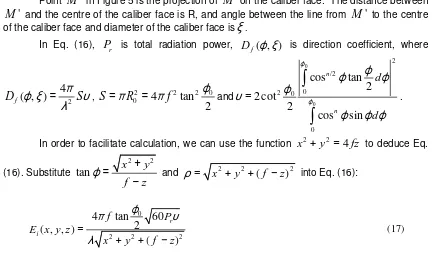
.In Eq. (16),
P
r is total radiation power,D
f( , )
ϕ ξ
is direction coefficient, where2
4
( , )
f
D
ϕ ξ
π
S
υ
λ
=
, 024
2tan
2 02
S
=
π
R
=
π
f
ϕ
and0
0
2 /2
0 2 0
0
cos
tan
2
2 cot
2
cos
sin
nn
d
d
ϕ
ϕ
ϕ
ϕ
ϕ
ϕ
υ
ϕ
ϕ ϕ
=
∫
∫
.
In order to facilitate calculation, we can use the function
x
2+
y
2=
4
fz
to deduce Eq.(16). Substitute
2 2
tan
x
y
f
z
ϕ
=
+
−
and2 2 2
(
)
x
y
f
z
ρ
=
+
+
−
into Eq. (16):0
2 2 2
4
tan
60
2
( , , )
(
)
r
i
f
P
E x y z
x
y
f
z
ϕ
π
υ
λ
=
Except unknown quantities x、y z, the others are all known. Once Dyadic Green’s 、 function in the rectangular cavity through Eq. (1) is got, we also gain field strength of any point in the cavity using Eq. (15).
5. The Data Analysis
In order to verify the accuracy of the proposed method, the Figure of environment and vibration chamber field distribution is concluded by MATLAB. At the same time, the result of field distribution in the chamber is got by FEKO. Comparing the two results, the method in this paper can be proved.
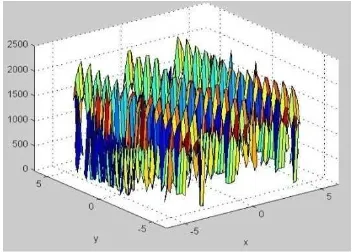
In the course of calculation, the radius of parabolic antenna is 30cm, the frequency is 1GHz. The results are shown in Figure 6 to Figure 9.
Figure 6. Field distribution in 1.8m away from origin of the chamber by MATLAB
Figure 7. Field distribution in 1.8m away from origin of the chamber by FEKO
Figure 8. Field distribution in 2.0m away from origin of the chamber by MATLAB
Figure 9. Field distribution in 2.0m away from origin of the chamber by FEK
O
Figure 6 is the electric field strength distribution in 1.8m away from origin of the chamber by MATLAB. Compare with Figure 7 that is the simulation result of FEKO in the same position. The two results both compos of peaks, the two results is similar. The average of peak values of the field distribution in 1.8m away from origin of the chamber is 1900V/m by MATLAB. And the average value by FEKO is 1679V/m. By MATLAB the average of field distribution is 969V/m. By FEKO average value is 898V/m. That means field distribution of two methods of calculating is approximately equal.
application of Dyadic Green’s functions. Because of Dyadic Green’s functions using the vector, there are large amount of data. Some simplified methods were used to reduce the amount of data in calculation, thus may cause some calculation errors. Through the experiment data, the results of MATLAB and the simulation results of FEKO are approximate. The correctness of this paper is proved. In addition, using Dyadic Green’s functions in MATLAB is more flexible, parameter settings are more direct, and calculation process is visible. All these advantages are FEKO doesn’t have.
Acknowledgments:
This paper is supported by the National Natural Science Foundation(61102105, 60775060) ; the National Postdoctoral Science Foundation under Grant No. 20080440840; the National Research Foundation for the Doctoral Program of Higher Education of China under No. 20102304120014, 20102304110006; the Natural Science Foundation of Heilongjiang Province of china under Grant No. F201029.
References
[1] Liang Xiao-liang. EMC Reverberation Chamber Development and Application Review. Civil Aircraft Design and Research. 2009: 60-61.
[2] Shen Yuan-mao,SHI Dan,GAO You-yang. Improvement in field uniformity introduced by
multiple-antenna in source Reverberation Chamber. Chinese Journal of Radio Science. 2009; 24(4): 682-686. [3] Charles F. Bunting. Statistical Characterization and the Simulation of a Reverberation Chamber
Using Finite-Element Techniques. IEEE Transactions on Electromagnetic Compatibility. 2003; 44(1): 214-221.
[4] WANG Yue,Lu Gui-zhen,Lin Jin-cai. Space Characteristics Measurement in Reverberation
Chamber. Journal of Communication University of China (science and technology). 2009; 16(1): 61-64.
[5] Zhang Xu-feng,Li Ying,Ni Gu-yan,etal. Hybrid model to evaluating shielding effectiveness of cavity
with apertures. Chinese Journal of Radio Science. 2011; 26(1): 26-28.
[6] David A. Hill. Electromagnetic Theory of Reverberation Chambers. National Institute of Standards and Technology.1998.
[7] Lv Fei-yan,Sha Fei. The Application of Dyadic Green’s Functions in Anechoic Chamber Analysis. Ship Electronic Engineering. 2004; 24(2): 76-77.
[8] A Jidin, T Sutikno. MATLAB/SIMULINK Based Analysis of Voltage Sorce Inverter with Space Vector Modulation. TELKOMNIKA. 2009; 7(1): 23-30.
[9] Mudrik Alaydrus. Hybrid Methods in Designing Sierpinski Gasket Antennas. TELKOMNIKA. 2010; 8(3): 225-234.