DOI: 10.12928/TELKOMNIKA.v15i1.3677 36
Open-circuit Fault Diagnosis for Grid-connected NPC
Inverter Based on Independent Component Analysis
and Neural Network
Xiaofeng Wan1, Hailin Hu2, Yunjun Yu*3, Liping Kang4, Fanpeng Zeng5 1,2,3
College of information Engineering, Nanchang University, Nanchang, 330031, JiangXi, China
4Wireless Laboratory, ZTE Co., Shenzhen 518000, China 5
Jiangsu Lin Yang energy Co., Ltd, Qidong 226200, Jiangsu, China *Corresponding author, e-mail: [email protected], [email protected]*3
Abstract
An open circuit (O-C) fault detection method for grid-connected neutral-point-clamped (NPC) inverter based on independent component analysis (ICA) and neural network (NN) is proposed in this paper. A NN classifier is applied to the fault diagnosis of NPC inverter. The ICA is utilized for the three phase current feature extraction. The ICA reduces the number of NN input neuron. A lower dimensional input space reduces the noise and the training time of NN, the ICA algorithm improves the mapping performance. The proposed algorithm is evaluated with simulation test set. The overall classification performance of the proposed network is more than 97%. The simulation results show that the proposed algorithm performs satisfactorily to fault location.
Keywords: NPC Inverter, fault diagnosis, independent component analysis, neural network
Copyright © 2017 Universitas Ahmad Dahlan. All rights reserved.
1. Introduction
The three-level NPC inverter has out-standing performances on harmonic distortion and efficiency, and it has been used in applications of wide-power range. The main disadvantage of the multilevel inverter is the more power semiconductors and the increasing malfunction probability compared with two-level inverters. Once a switching fault occurs, the inverter need to stop to ensure the safety. Therefore, the diagnosis of the multi-level inverter fault is of great significance [1, 2].
Research on the reliability improvement of application is an important issue. In the NPC inverter, twelve insulated gate bipolar mode transistors (IGBTS) in three legs are used as the
switching device. IGBTs’ faults can be classified into a short circuit (S-C) faults and open circuit (O-C) faults. Usually S-C faults cause an overcurrent condition that is readily detected and acted upon by standard protection systems, such as over-current or over-voltage protection. Generally O-C faults do not trigger standard fault protection, O-C faults diagnosis become critical for NPC inverter [1-3].
The O-C fault diagnostic techniques of inverters can be divided into four primary kinds: 1) waveform based; 2) component based; 3) model based; 4) classifier based [4, 5].
In component-based techniques, switches are individually monitored with gate signal, voltage, current, and heating, some of these sensors are integrated into the switches or into the analog circuitry of inverter system to detect switch abnormalities, and the time is relatively fast,
i.e., less than 10 μs [4-8]. Although this can lead to many of the benefits indicated above, it often comes at increased enforcement costs and the implementation complexity.
affected by the load. Therefore, the analysis of pole voltage can be used to diagnose the fault of inverter. The closed-loop schemes of the inverter can mask these fault features. Furthermore, the output waveforms can be affected by the normal transient phenomena and faulty conditions, which can result in diagnostics failure [5].
In model-based techniques, the measured indicators are compared with the estimated values obtained from control reference signals and system modeling (current errors, voltage errors) [17-22]. For classifier-based techniques, a faulty switch is recognized via advanced classifier algorithms with no requiring real-time estimations [5]. The data obtained from test and simulation is needed in the process of classifier offline training, while classification is carried out using fuzzy logic, neural networks(NN), artificial intelligence, machine learning, support vector machine(SVM) [23-31]. The fault feature extraction methods (multi-resolution analysis, fast fourier transformation (FFT), wavelet transform, principal component analysis (PCA)) [18, 19] [24-26], classifier structure, and training process determine the performance of classifier-based techniques.
Furthermore, classifier-based techniques can be integrated with waveform processing techniques to improve diagnostic performance. The boundary lines between normal and abnormal features are often fuzzy [32-35]. The proposed techniques in [32-35] have a good classification performance to classify healthy and unhealthy conditions. However, many neurons are used to train the network (i.e., one neuron for each harmonic), and the training of classifier take a long time. ICA is a method which can reduce the dimensionality of an input space with no losing important information, and the transformed vectors are uncorrelated and orthogonal. The ICA method could be used to reduce the number of input neurons. A lower dimensional input could also speed up the training process, reduce the noise, and improve the mapping performance.
This paper is outlined as follows: O-C fault diagnostic techniques for inverters are introduced in Section I. Then the NPC inverter topology and O-C faults analysis are shown in Section II. After that, the ICA fault feature extraction and the NN classifier are provided in Section III. Then, the proposed diagnostic algorithms are evaluated and verified in simulation in Section IV. After that, a discussion and comparison between the proposed diagnostic algorithms and the former algorithms in the previous researches are given in Section V. Finally, Section VI provides the conclusion of this paper.
2. Inverter Topology and Faults Analysis 2.1. NPC Inverter with Brief Description
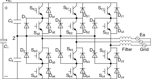
Figure 1 shows a simplified circuit diagram of the grid-connected three-level NPC inverter. The operating status of the switch and the pole voltage in the NPC inverter can be
represented by the switching states shown in Table 1. The switching state “P” indicates that the
two upper switches Sx1 and Sx2 are ON, the pole voltage Vxz is VDC/2, Vxz is the voltage at
terminal x (x = a, b, c) with respect to the neutral point voltage Z. The switching state “O”
denotes that the two inner switches Sx2 and Sx3 are ON and Vxzis zero. The switching state “N”
signifies that the two lower switches Sx3 and Sx4 are ON and Vxzis −VDC/2 [11]. Figure 2 shows
the current paths according to the switching state and phase current direction.
Sa1
Sa2
Sa3
Sa4
Sb1
Sb2
Sb3
Sb4
Sc1
Sc2
Sc3
Sc4
C2
C3
Z
C1
VdC
Filter Grid
Da1
Da2
Da3
Da4
D1
D2 D4
D3
Db1
Db2
Db3
Db4
Dc3
Dc4
Dc2
Dc1
D5
D6
Ea
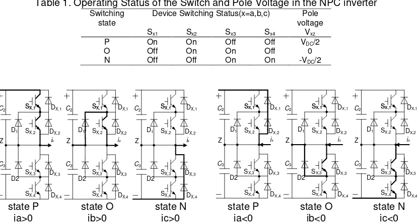
Table 1. Operating Status of the Switch and Pole Voltage in the NPC inverter Switching
state Device Switching Status(x=a,b,c) voltage Pole
Sx1 Sx2 Sx3 Sx4 Vxz
P On On Off Off VDC/2
O Off On On Off 0
N Off Off On On -VDC/2
SX,1 SX,2 SX,3 SX,4 C2 C3 Z ix SX,1 DX,1 DX,2 DX,3 DX,4 D1 D2 SX,1 SX,2 SX,3 SX,4 C2 C3 Z ix SX,1 DX,1 DX,2 DX,3 DX,4 D1 D2 SX,1 SX,2 SX,3 SX,4 C2 C3 Z ix SX,1 DX,1 DX,2 DX,3 DX,4 D1 D2 SX,1 SX,2 SX,3 SX,4 C2 C3 Z ix SX,1 DX,1 DX,2 DX,3 DX,4 D1 D2 SX,1 SX,2 SX,3 SX,4 C2 C3 Z ix SX,1 DX,1 DX,2 DX,3 DX,4 D1 D2 SX,1 SX,2 SX,3 SX,4 C2 C3 Z ix SX,1 DX,1 DX,2 DX,3 DX,4 D1 D2
state P state O state N state P state O state N
ia>0 ib>0 ic>0 ia<0 ib<0 ic<0
Figure 2. Shows the Current Paths According to the Switching State and Phase Current Direction
In Figure 3 the proposed closed-loop control scheme is shown. The inverter control is based on a decoupled control of the active and reactive power. The Pref is set by a PI controller that compares the actual DC bus voltage and the reference generated by the MPPT, and provides id active current reference in a synchronous reference frame attached at grid voltage vector. The other component of current vector iq represents the reactive current. It can be fixed at zero to maintain almost unity power factor, also it can be compensated the reactive power of the load. The reactive power of the load is calculated using the αβ reference frame. idref and iqref can be calculated with power control. After that, the Vdref and Vqref can be obtained from the
current PI control. By applying the inverse Park transformation to αβ vector components, the desired references (Vαref and Vβref) are obtained. These are passed to inverter control which gives outputs of pulses to drive the multilevel inverter switches. The switching pattern generation is achieved using Space Vector Pulse Width Modulation (SVPWM) technique [36, 37]. + -PI + -abc dq PLL Power control dq ref P ref Q d
u uq
d
i iq
dref i qref i qref u dref u
i i ia, ,b c
, ,
a b c
u u u
DC V Filter Grid SVPWM Figure 3. Block Diagram for the Proposed Control Scheme
2.2. O-C Fault Analysis
Table 2. Switching States in Faulty Mode Faulty switch Possible state Impossible state
Sx1 O,N P
Sx2 N O,P
Sx3 P O,N
Sx4 O,P N
In this section, the operation of the NPC inverter under the open-circuit fault is analyzed considering the open-circuit in two semiconductor elements simultaneously at most, as it is rare that more than two switching device fails at the same time.
1. Open fault in switch Sx1
When the switching state is “P,” the open-switch fault occurs in Sx1, D1 becomes
reverse-biased. The grid phase voltage Exs is the voltage between the grid and ground. The
current path is opened, and the positive phase current becomes zero. If Exs is higher than the
dc-link voltage (VDC/2), the current path is formed through diodes Dx1 andDx2. Since this period is
very short and the potential difference is very small, the negative phase current is almost zero. 2. Open fault in switch Sx2
When the open-switch fault occurs in switch Sx2 while the switching state is “P,” the
phase current does not flow, because the phase current path is opened. Even when the
switching state is “O,” the phase current path is not formed, because the switch Sx2 is opened. If
Exs is higher than Vxz , the phase current is formed through switch Sx3 and diode D2. However,
the negative phase current does not flow, because this period is very short. 3. Open fault in switch Sx3
When the switching state is “N,” the phase current path is opened because of the
occurrence of the open-switch fault in switch Sx3. The negative phase current becomes zero.
Even when the switching state is “O,” the phase current path is not formed, because switch Sx3
is opened. The path is formed through diode D1 and switch Sx2 when Vxz is higher than Exs.
However, the positive phase current does not flow because of the abovementioned reasons. 4. Open fault in switch Sx4
When the open-switch fault occurs in switch Sx4 while the switching state is “N,” diode
D2 becomes reverse biased. The current path follows the open circuit, and the phase current
becomes zero.
(a) (b)
Figure 4. One switch with O-C fault in phase a
(a) (b)
Figure 5. Two Switch With O-C Fault in Phase a 0.08 0.09 0.1 0.11 0.12 0.13 0.14
-6 -4 -2 0 2 4 6
Ia Ib Ic
Normal Sa1 Fault
0.08 0.09 0.1 0.11 0.12 0.13 0.14 -6
-4 -2 0 2 4 6
Ia Ib
Normal
Ic
Sa2 Fault
0.08 0.09 0.1 0.11 0.12 0.13 0.14
-6 -4 -2 0 2 4 6
Ia Ib
Normal
Ic
Sa2 Sa4 Fault
0.08 0.09 0.1 0.11 0.12 0.13 0.14
-6 -4 -2 0 2 4 6
Ia Ib
Normal
Ic
(a) (b)
Figure 6. Two Switch with O-C fault in Phase a and Phase b
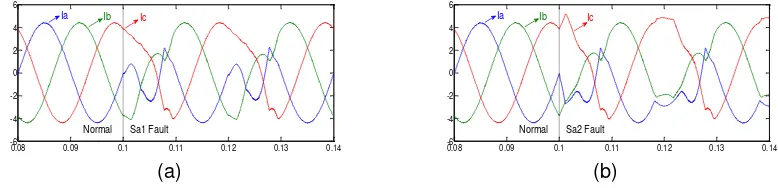
As the closed-loop control of the system, three phase currents interact with each other. Figure 4(a) and (b) show the output phase current ix for faults in switches Sa1 and Sa2
respectively; Figure 5(a), (b) denote the phase current ix for two switches faults in leg a,
respectively; Figure 6(a), (B)indicate the phase current ix for two switches faults in leg a and leg
b respectively. As in the previous analysis, the phase current waveform is distorted. The fault feature is integrated in the three phase currents waveforms, and it is difficult to diagnosis with the experience.
3. Fault Diagnosis of NPC Inverter 3.1. Structure of Fault Diagnostic System
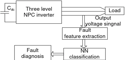
The structure for a fault diagnosis system is illustrated in Figure 7. The system is composed of the following four major states: 1) fault feature extraction; 2) NN classification; 3) fault diagnosis. The feature extraction performs the current input signal transformation, with rated signal values as important features, and the output of the transformed signal is transferred to NN classification. The networks are trained with normal data, all fault feature data, and corresponding output assigned as binary code; thus, the output of this network is nearly 0 and 1 as binary code. The binary code is sent to the fault diagnosis to decode the fault type and its location.
Three level
NPC inverter Output Load
voltage singnal Fault
feature extraction
NN classification Fault
diagnosis Cdc
Figure 7. Structure of the Fault Diagnosis System
3.2. Fault Feature Extraction Based on ICA
As can be seen from Figure 4, Figure 5, and Figure 6, the signals are difficult to rate as an important characteristic for classifying a fault hypothesis, and they have high correlation with each other. Hence, a signal transformation technique is needed. Basically, ICA is statistical and computational method for find the hidden factor which unknown in random variables, measurements and signals. ICA is extended from blind source separation method. ICA is a one of other popular method to separate the brain signal from ocular artifact in EEG signal. The concept of ICA lies in the fact that the signals may be decomposed into their constituent independent component. The mixed sources signal can be assumed independent from each other, this concept plays crucial role in separation source signal from mixed signal. One of the
approaching ICA’s methods uses the highest order from cumulant tensor. Joint approximate
diagonalization of eignematrices (JADE) is one of the methods to find the eigenvalue from cumulant tensor.
0.08 0.09 0.1 0.11 0.12 0.13 0.14 -6
-4 -2 0 2 4 6
Ia Ib
Normal
Ic
Sa1 Sb1 Fault
0.08 0.09 0.1 0.11 0.12 0.13 0.14
-6 -4 -2 0 2 4 6
Ia Ib
Normal
Ic
In this paper, the output current waveform is expressed by the matrix Xnl, the n
represents the number of current sensors, l represents the number of the samples in one cycle. For example, the Xnl represents the value of n sensor in l sample.
(1)
(2)
( )
(1)
(2)
( )
(1)
(2)
( )
1 1 1 1
2 2 2 2
n n n n
x
x
x
x l
x
x
x
x l
X
x
x
x
x l
(1)
If the noise can be ignored or it has been reduced to an acceptable before the separation. X can be express as the equation: X=AR.
A is the matrix of pure signal proportions (the mixing matrix), while R is the matrix of pure source signals. The meaning of these equations is that the signals in the rows of X are linear mixtures of pure source signals (in the rows of R), the weights being given in the corresponding columns of A. The objective of ICA is to find physically meaningful vectors S, called the Independent Components, which represent the rows of R, when both A and R is unknown. The linear relationship between the matrixes is shown as Equation 2.
T
S W X
(2)The matrix Xnl can be converted into a sparse matrix S=[s1 , s2,…, sl ]T by the formulae (2), and the sparse matrix S=[s1 , s2,…, sl ]T is the fault feature vectors of
Xnl based on ICA sparse coding algorithms. Therefore, the process of seeking fault feature vector S is to select the weight matrix W which is match with the feature of the input signal matrix Xnl, and calculate the feature vector matrix S [38].
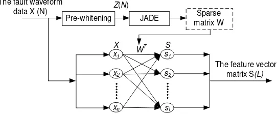
The structure for a feature extraction is illustrated in Figure 8. The system is composed of the following two major states: 1) obtaining the weight matrix W based on JADE; 2) fault feature extraction based on ICA. When the NPC inverter occur OC fault, the sensor sampled the three-phase current, the sampling data construct sparse coding algorithm aliasing signal X(N). First, the matrix X(N) is processed by pre-whitening method. Next, the sparse matrix W is calculated with JADE algorithm. Finally, according to Equation 2, the feature vector matrix S can be calculated with the fault waveform data X(N) and sparse matrix W [39].
x1
x2
xn
s1
s2
Pre-whitening JADE matrix WSparse
X WT S
The fault waveform
data X (N) Z(N)
The feature vector matrix S(L)
sl
Figure 8. The Fault Feature Extraction Based on Sparse Coding Algorithms of NPC Inverter
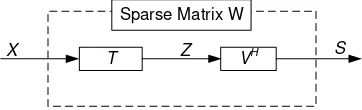
T VH
X Z S
Sparse Matrix W
Figure 9. Block Diagram of JADE Algorithm
T
TE ZE Z ZE Z D D (3)
1
2 T
X D D (4)
Since V is n×n dimensional unitary matrix, S=VHZ=VHTX, where the superscript H is the conjugate transpose representation symbols. According to equation S=WTX,it can be obtained that WT=VHT. The estimation of the matrix W can be converted into calculation the unitary matrix V, and the estimate of V is determined by fourth-order cumulant Qz(M).
The fourth order cumulant can be obtained with the Equation 5. The n2 fourth order cumulant can be calculated in order. A fourth order cumulant can form a fourth order cumulant matrix as the Equation 6 [40, 41].
4
( , , , )
i j k l i j k l i j k li k j l i l j k
Cum z z z z
E z z z z
E z z E z z
E z z E z z
E z z E z z
(5)
4 , 1
[
z(
)]
ij n( ,
i j,
k,
l)
lk1
, , ,
k l
Q M
Cum z z z z m
i j k l
n
(6)Where mlk is an element of the matrix M, M is a n×n matrix. [Qz (M)]ij is the (i, j) elements of the matrix Qz(M). Cum4 (·) is the fourth-order cumulant.
It is proved that the fourth-order cumulant of Qz(Mi) can be approximately diagonalize by the unitary matrix V . So the unitary matrix V can be obtained by diagonalizing the fourth-order cumulant of Qz(Mi). The approximate diagonalization of Qz(M) is based on the Jacobi algorithm, and aims at minimizing the sum-of-squares of the off-diagonal elements. And the W can be obtained as the equation WT=VHT.
3.3. NN Classification
The multilayer feedforward networks are used in this paper. The original data from the feature extraction system (ICA) that are used to train and test the NN are exactly the same data set. The input layer has 10 neurons; the hidden layer and output layer contain 30 and 6 neurons respectively. Output of NN which are 6 binary bits standing for the fault locations. The sigmoid activation function is used: tansig for hidden nodes and logsig for an output node. A logsig activation function is used for an output node because the target output is between 0 and 1. It should be noted that the number of nodes for the input and output layers depends on the specific application. The selection of number and dimension in the hidden layer is based on NN accuracy in preliminary tests.
4. Simulation Validation
To verify the proposed fault diagnostic method, simulation was carried out in Matlab/Simulink environment. The system simulated here is composed of a dc supply, dc-link capacitors, three-level NPC inverters, a three-phase RL load, and a three-phase programmable voltage source. The modulation method is SVPWM. The carrier frequency and the reference fundamental frequency are 10 kHz and 50 Hz, respectively. In this section, the feature extraction based on the sparse coding is analysis by giving an example, the OC fault occur in Sa,1 and Sb,4 simultaneously under 500V/5kW conditions, and observation matrix Z is shown as
follows:
.00677
1.1667
1.6932
1.8481 2.0219
0.0635
2.5207
4.1542
4.2068
3.3570
3.7596 0.0361
0.3021 1.5164
1.1763
3.7844
4.3556
3.3148
0.9770
0.7121
3.8273
1.1306
1.9953
0.3317
3.1982
3.8479
1.8349
0.8349 3.2298
4.0690
-
-
-
-
-
-
-
-Z
-
-
--
-
-
-
(7)
The sparse matrix W is obtained based on JADE algorithm, W is shown as follows:
[0.0666 0.1704 0.2370]
W
(8)After W is acquired successfully, it will be able to obtain the fault feature vector S as the SA,1 and SB,4 with OC fault simultaneously, and S is shown as follows:
1.5525
0.3395
0.6372 0.0567 1.0933 1.5613 1.0094 0.0893
0.8793
1.3095
S
(9)The fault feature vectors S of all O-C faults can be obtain according to the above method under 500V/5kW conditions. The training data set should also cover the operation region, thus the training set is generation from simulation with various operation points (the input voltage of the inverter is taken value as 450V, 500V, 550V, 600V, load power is taken value as 2kW, 5kW, 10kW.). A total of 78 × 12 = 936 fault types are taken into the training process. The performance index function of NN is MSE≤0.01.
The RMS error function MSE is less than 0.01, and the iterative steps is 28, the training has high efficiency, and the consuming time is 5 seconds. After the network learning, the property Gradient is 0.00679, the momentum parameter is 1×10⁻⁶, the maximum number of
failed to validate data is 0.
The test set is generated from simulation with the 78 OC faults under 500V/10kW, 76 kinds of faults are accurately diagnosed, error data was appeared in individual bits under two conditions, one is the SA,1 and SB,3 occur OC fault simultaneously, the other is the SC,4 and SB,3
occur OC fault simultaneously, and the diagnostics fail due to the influence of system observation noise. The diagnostic accuracy rate is 97%. The diagnostic results of two switches in different legs are shown in appendix 1. According to the result from simulation, Fault diagnosis has been successfully applied in NPC inverter based on sparse coding fault feature extraction and NN Classification method.
5. Comparison
The ICA-NN has 97% classification performance and the time necessary to train the NN is 4 second. The wavelet analysis method mentioned in [25] is utilized for feature extraction; the input layer of NN classifier has 16 neurons. For easy to compare, the number of the hidden nodes is 10, the RMS error function MSE is less than 0.01, the iterative steps is 64, the time consuming is 19 seconds. The faults diagnostic rate is 93%. The FFT method mentioned in [35] is utilized for feature extraction, and the input layer of NN classifier has 30 neurons. For easy to compare, the number of the hidden nodes is 10, the RMS error function MSE is less than 0.01, the iterative steps is 78, the time consuming is 35 seconds. The faults diagnostic rate is 91%.
generally higher than that under the condition of the wavelet analysis and FFT. It is obvious that the ICA method can reduce the iterative steps obviously, and improve the accuracy of fault diagnosis. The comparative data are shown in Table 3.
Table 3. Comparison Table of Two Feature Extraction Methods in Fault Diagnosis Feature extraction methods The number of hidden nodes Iterative steps Time/s Accuracy of diagnosis
FFT
18 79 35 91.02%
20 82 36 91.02%
22 79 38 92.31%
24 81 40 93.59%
26 85 42 92.31%
28 92 45 92.31%
30 91 48 91.02%
32 96 49 93.59%
Wavelet analysis
18 48 9 89.74%
20 52 11 91.02%
22 56 13 92.31%
24 57 14 93.59%
26 55 16 92.31%
28 56 12 92.31%
30 64 19 93.59%
32 72 21 93.59%
ICA
18 30 4 96.15%
20 28 4 96.15%
22 35 4 98.72%
24 26 3 98.72%
26 28 4 98.72%
28 27 4 93.59%
30 28 5 97.44%
6. Conclusion
In this paper, an algorithm for NPC grid-connected inverter O-C fault, based on the ICA fault feature extraction and NN classifier. The simple and effective fault feature vector of phase current is obtained with ICA. NN Classification is used to classify the fault. This algorithm relies only on current signals already used by the inverter controller and therefore does not require any additional sensors. The location of O-C fault switches can be identified by this method when the fault occurred. The simulation and experimental results confirm the feasibility and effectiveness of the proposed fault-detection method.
Acknowledgements
This work was financially supported by the National Natural Science Foundation of China (No. 61563034), the Natural Science Foundation of Jiangxi Provincial (No.20151BAB206051), the Project of Jiangxi Province Higher Educational Science and Technology Loading Program (No. KJLD14006).
References
[1] JD Barros, JFA Silva, ÉGA Jesus. Fast-predictive optimal control of NPC multilevel converters. IEEE Trans. Industrial Electronics. 2013; 60(2): 619-627.
[2] M Malinowski, K Gopakumar, J Rodriguez, MA Pérez. A survey on cascaded multilevel inverters.
IEEE Trans. Industrial Electronics. 2010; 57(7): 2197-2206.
[3] J Rodriguez, S Bernet, PK Steimer, IE Lizama. A survey on neutral-point-clamped inverters. IEEE Trans. Industrial Electronics. 2010; 57(7): 2219-2230.
[4] L Bin, SK Sharma. A literature review of IGBT fault diagnostic and protection methods for power inverters. IEEE Trans. Industry Applications. 2009; 45(5): 1770-1777.
[5] Mirafzal B. Survey of fault-tolerance techniques for three-phase voltage source inverters. IEEE Trans. Industrial Electronics. 2014; 61(10): 5192-5202.
[6] DW Brown, M Abbas, A Ginart, IN Ali, PW Kalgren, GJ Vachtsevanos. Turn-off time as an early indicator of insulated gate bipolar transistor latch-up. IEEE Trans. Power Electronics. 2012; 27(2):
479-489.
Hernandez-Gonzalez, J Aguayo Alquicira. A failure-detection strategy for IGBT based on gate-voltage behavior applied to a motor drive system. IEEE Trans. Industrial Electronics. 2011; 58(5), 1625-1633.
[8] TJ Kim, WC Lee, DS Hyun. Detection method for opencircuit fault in neutral-point-clamped inverter systems. IEEE Trans. Industrial Electronics. 2009; 56(7): 2754-2763.
[9] P Lezana, R Aguilera, J Rodrguez. Fault detection on multicell converter based on output voltage frequency analysis. IEEE Trans. Industrial Electronics. 2009; 56(6): 2275-2282.
[10] W Sleszynski, J Nieznanski, A Cichowski. Open-transistor fault diagnostics in voltage-source inverters by analyzing the load currents. IEEE Trans. Industrial Electronics. 2009; 56(11): 4681-4688.
[11] Shi L, Zhou B. Phase Open Fault Tolerant Control of High Reliability Doubly-Salient Wound-Field Machine. TELKOMNIKA (Telecommunication Computing Electronics and Control). 2014; 12(2):
325-332.
[12] MS Mendes, MB Abadi, SMA Cruz. Fault diagnostic algorithm for three-level neutral point clamped
AC motor drives, based on the average current Park’s vector. IEEE Trans. Power Electronics. 2014;
7(5): 1127-1137.
[13] Abadi MB, Mendes AMS, Cruz SMA. Three-level NPC inverter fault diagnosis by the average current Park’s vector approach. In Proceedings 20th International Conference on Electrical Machines (ICEM), IEEE. 2012: 189-1898.
[14] Kim TJ, Lee WC, Hyun DS. Detection method for open-circuit fault in neutral-point-clamped inverter systems. IEEE Trans. Industrial Electronics. 2009; 56(7): 2754-2763.
[15] K Rothenhagen, FW Fuchs. Performance of diagnosis methods for IGBT open circuit faults in three phase voltage source inverters for ac variable speed drives. In Proceedings 2005 European
Conference on Power Electronics and Application. 2005: 1-10.
[16] K Rothenhagen, FW Fuchs. Performance of diagnosis methods for IGBT open circuit faults in voltage source active rectifiers. In Proceedings 2004 IEEE 35th Annual Power Electronics Specialists
Conference, IEEE. 2004: 4348-4354.
[17] JO Estima, AJ Marques Cardoso. A new algorithm for real-time multiple open-circuit fault diagnosis in voltage-fed PWM motor drives by the reference current errors. IEEE Trans. Industrial Electronics.
2013; 60(8): 3496-3505.
[18] DR Espinoza-Trejo, DU Campos-Delgado, E Barcenas, FJ Martiinez-Loipez. Robust fault diagnosis scheme for open-circuit faults in voltage source inverters feeding induction motors by using nonlinear proportional-integral observers. IET Power Electronics. 2012; 5(7): 1204-1216.
[19] S Li, L Xu. Fault detection for modular multilevel converters based on sliding mode observer. IEEE Trans. Power Electronics. 2013; 28(11): 4867-4872.
[20] C Choi, W Lee. Design and evaluation of voltage measurement based sectoral diagnosis method for inverter open switch faults of permanent magnet synchronous motor drives. IET electric power applications. 2012; 6(8): 526-532.
[21] RLA Ribeiro, CB Jacobina, ERC Silva, AMN Lima. Fault detection of open-switch damage in voltage-fed PWM motor drive systems. IEEE Trans. Power Electronics. 2003; 18(2): 587-593.
[22] LMA Caseiro, AMS Mendes, P Lopes. Open-circuit fault diagnosis in Neutral-Point-Clamped active power filters based on instant voltage error with no additional sensors. In Proceedings 30th Annual
IEEE Applied Power Electronics Conference and Exposition, IEEE. 2015: 2217-2222.
[23] X Yang, C Wang, L Shi. Study of IGBT open-circuit fault diagnosis method for H-bridge inverter.
Electric Machines & Control/Dianji Yu Kongzhi Xuebao. 2014; 18(5): 112-118.
[24] PG Potamianos, ED Mitronikas, AN Safacas. Open-circuit fault diagnosis for matrix converter drives and remedial operation using carrier-based modulation methods. IEEE Trans. Industrial Electronics.
2014; 61(1): 531-545.
[25] R Hua, P Ji. Research on the NPC Three-Level Inverter Fault Feature Extraction Method Based on Wavelet Analysis. Applied Mechanics and Materials. 2014; 49(4): 1410-1413.
[26] T Kamel, Y Biletskiy, L Chang. Fault Diagnoses for Industrial Grid-Connected Converters in the Power Distribution Systems. IEEE Trans. Industrial Electronics. 2015; 62(10): 6496-6507.
[27] L Hong-da, Y Wen-jie, L Hai, Z Dian-hua. Fault diagnosis method in controlled rectifier based on support vector machines. In Proceedings 2010 2nd WRI Global Congress on Intelligent Systems (GCIS). 2010: 235-238.
[28] Ondel G Clerc, E Boutleux. Fault detection and diagnosis in a set inverter-induction machine through multidimensional membership function and pattern recognition. IEEE Trans. Energy Conversion.
2009; 24(2): 431-441.
[29] F Zidani, MEH Benbouzid, D Diallo, et al. Induction motor stator faults diagnosis by a current Concordia pattern-based fuzzy decision system. IEEE Trans. Energy Conversion. 2003; 18(4): 469-475.
[30] S Khomfoi, LM Tolbert. Fault diagnostic system for a multilevel inverter using a neural network. IEEE Trans. Power Electronics. 2007; 22(3): 1062-1069.
[31] MR Mamat, M Rizon, MS Khanniche. Fault detection of 3-phase VSI using wavelet-fuzzy algorithm.
[32] S Khomfoi, LM Tolbert. Fault diagnostic system for multilevel inverters using a neural network. IEEE Trans. Power Electronics. 2007; 22(3): 1062-1069.
[33] F Zidani, D Diallo, MEH Benbouzid, R Nait-Said. A fuzzy based approach for the diagnosis of fault modes in a voltage-fed PWM inverter induction motor drive. IEEE Trans. Industrial Electronics. 2008;
55(2): 586-593.
[34] Khomfoi S, Tolbert LM. Fault diagnosis and reconfiguration for multilevel inverter drive using AI-based techniques. IEEE Trans. Industrial Electronics. 2007; 54(6): 2954-2968.
[35] Wei J, Cong W, Yao-pu L, et al. Fault detection and remedy of multilevel inverter based on BP neural network. In Proceedings 2012 Asia-Pacific Power and Energy Engineering Conference, IEEE. 2012:
1-4.
[36] Ravi A, Manoharan PS, Anand JV. Modeling and simulation of three phase multilevel inverter for grid connected photovoltaic systems. Solar Energy. 2011; 85(11): 2811-2818.
[37] Tsengenes G, Nathenas T, Adamidis G. A three-level space vector modulated grid connected inverter with control scheme based on instantaneous power theory. Simulation Modelling Practice and Theory. 2012; 25:134-147.
[38] Fachrurrozi M, Mujtahid M. Iris Image Recognition Based on Independent Component Analysis and Support Vector Machine. TELKOMNIKA (Telecommunication Computing Electronics and Control). 2015; 13(2): 597-603.
[39] P Xu, N Song, C Yu, et al. Open-circuit fault diagnosis and fault-Tolerant strategies for full-bridge DC-DC converters. IEEE Trans. Power Electronics. 2012; 27(5): 2550-2565.
[40] TJ Kim, WC Lee, DS Hyun. Detection method for open-circuit fault in neutral-point-clamped inverter systems. IEEE Trans. Industrial Electronics. 2009; 56(7): 2754-2763.
[41] De Moura NN, JM Seixas, AV Greco. Independent component analysis for optimal passive sonar signal detection. In Proceedings 7th International Conference on Intelligent Systems Design and
Applications (ISDA). 2007: 671-675.
Appendix 1.
The comparison table of Neural network actual output and expected output
Order Actual output Expected output Fault type
1 0.0058 0.0458 0.0823 0.0127 0.9823 0.9716 000011 SA,1,SB,4
2 0.00634 0.0258 0.0625 0.9789 0.0562 0.0467 000100 SA,1,SC,4
3 0.0463 0.0851 0.0063 0.0428 0.9621 0.0186 000010 SB,1,SA,4
4 0.0358 0.0578 0.0023 0.9752 0.9920 0.0872 000110 SB,1,SC,4
5 0.0067 0.0249 0.0028 0.9987 0.0031 0.9621 000101 SC,1,SA,4
6 0.0267 0.0128 0.0000 0.9687 0.9234 0.9841 000111 SC,1,SB,4
7 0.0283 0.0025 0.9634 0.0120 0.0572 0.0423 001000 SA,1,SB,1
8 0.0149 0.0238 0.9628 0.0275 0.9357 0.9837 001011 SA,1,SC,1
9 0.0658 0.0073 0.9752 0.9946 0.0157 0.9867 001101 SB,1,SC,1
10 0.0243 0.0048 0.9856 0.0378 0.0189 0.9875 001001 SA,4,SB,4
11 0.0216 0.0578 0.9682 0.0358 0.9761 0.0248 001010 SA,4,SC,4
12 0.0325 0.0276 0.9927 0.9856 0.0135 0.0057 001100 SB,4,SC,4
13 0.0059 0.0327 0.9654 0.9831 0.9967 0.0159 001110 SA,2,SB,3
14 0.0038 0.9729 0.0183 0.0206 0.0579 0.9953 010001 SA,2,SC,3
15 0.0176 0.0089 0.9563 0.9468 0.9953 0.9709 001111 SB,2,SA,3
16 0.0049 0.9956 0.0025 0.0358 0.9956 0.0076 010010 SB,2,SC,3
17 0.0028 0.9752 0.0159 0.0127 0.0267 0.0089 010000 SC,2,SA,3
18 0.0263 0.9951 0.0259 0.0347 0.9942 0.9827 010011 SC,2,SB,3
19 0.0159 0.9957 0.0246 0.9756 0.0028 0.1586 010100 SA,2,SB,2
Order Actual output Expected output Fault type
21 0.0258 0.9684 0.9856 0.0023 0.0075 0.9854 011001 SB,2,SC,2
22 0.0237 0.9561 0.0327 0.9563 0.0157 0.9985 010101 SA,3,SB,3
23 0.0123 0.9752 0.0127 0.9856 0.9631 0.0258 010110 SA,3,SC,3
24 0.0150 0.9990 0.9993 0.0005 0.0073 0.0071 011000 SB,3,SC,3
25 0.0123 0.0258 0.9956 0.0128 0.9753 0.9846 011011 SA,1,SB,3
26 0.0158 0.9649 0.9957 0.9651 0.0095 0.0158 011100 SA,1,SC,3
27 0.0005 0.9983 0.9995 1.0000 1.0000 0.9952 011111 SB,1,SA,3
28 0.9756 0.0258 0.0025 0.0543 0.0018 0.0086 100000 SB,1,SC,3
29 0.9536 0.0489 0.0158 0.0259 0.9759 0.0005 100010 SC,1,SA,3
30 0.9672 0.0158 0.0046 0.9951 0.0527 1.0000 100101 SC,1,SB,3
31 0.0284 0.9687 0.9928 0.9567 0.9986 0.0257 011110 SA,2,SB,4
32 0.9684 0.0158 0.0297 0.0253 0.9957 0.9961 100011 SA,2,SC,4
33 0.0158 0.9927 0.9689 0.0054 0.9998 0.0128 011010 SB,2,SA,4
34 0.9967 0.0237 0.0158 0.9853 0.0275 0.0045 100100 SB,2,SC,4
35 0.0027 0.9456 0.9853 0.9967 0.0024 0.9967 011101 SC,2,SA,4
36 0.9985 0.0004 0.0185 0.0259 0.0158 0.9645 100001 SC,2,SB,4
37 0.9854 0.0056 0.0359 0.9864 0.9682 0.0009 100110 SA,1,SB,2
38 0.9867 0.0159 0.9894 0.0258 0.0159 0.9876 101001 SA,1,SC,2
39 0.9964 0.0025 0.9659 0.1569 0.9867 0.1567 101010 SB,1,SA,2
40 0.9852 0.0018 0.9998 0.9853 0.0005 1.0000 101101 SB,1,SC,2
41 0.9964 0.0157 0.9961 0.9568 1.0000 0.9864 101111 SC,1,SA,2
42 0.9752 0.9964 0.0128 0.0458 0.0085 0.9967 110001 SC,1,SB,2
43 0.9867 0.0084 0.9856 0.0158 0.9753 0.9579 101011 SA,3,SB,4
44 0.9826 0.0237 0.9617 0.9756 0.9956 0.0157 101110 SA,3,SC,4
45 0.9956 0.0058 0.0146 0.9657 0.9964 1.0000 100111 SB,3,SA,4
46 0.9547 0.9657 0.0059 0.0128 0.0157 0.9659 110000 SB,3,SC,4
47 0.9659 0.0453 0.9954 0.0089 0.0246 0.0257 101000 SC,3,SA,4