Force Characterization of a Rotary Motion Electrostatic Actuator based on
Finite Element Method (FEM) Analysis
MD GHAZALY Mariam
1,a, TAN Aik Choon
1, CHE AMRAN Aliza
1and SATO Kaiji
21Center for Robotic and Industrial Automation (CeRIA), Faculty of Electrical Engineering,
Universiti Teknikal Malaysia Melaka, Hang Tuah Jaya, 76100 Durian Tunggal, Melaka, Malaysia
2
Interdisciplinary Graduate School of Science and Engineering, Tokyo Institute of Technology,
4259-G2-17 Nagatsuta Midori-ku, Yokohama 226-8502, Japan
a
Keywords: Rotary Motion, Rotary Actuator, Electrostatic Actuator, Actuation Thrust Force, FEM Analysis.
Abstract. Two types of rotary motion electrostatic actuators were designed and analyzed using Finite Element Method (FEM) analysis. This paper discussed the comparisons and detailed thrust force analysis of
the two actuators. Both designs have similar specifications; i.e the number of rotor’s teeth to stator’s teeth
ratio, radius and thickness of rotor, and gap between stator and rotor. Two structures were designed & evaluated; (a) Side-Driven Electrostatic Actuator and (b) Bottom-Driven Electrostatic Actuator. The paper focuses on comparing & analyzing the generated electrostatic thrust force for both designs when the electrostatic actuator’s parameters are varied. Ansys Maxwell 3D software is used to design and analyze the generated thrust force of the two rotary motion electrostatic actuators. The FEM analyses have been carried out by (i) varying the actuator size; (ii), varying the actuator thickness and (iii) varying the actuator teeth ratio. The FEM analysis shows that the Bottom-Drive Electrostatic Actuator exhibit greater thrust force,
4931.80N compared to the Side-Drive Electrostatic Actuator, 240.96N; when the actuator’s radius is
700m, thickness is 50m, gap between the stator and rotor is 2m and the teeth ratio is 16:12.
Introduction
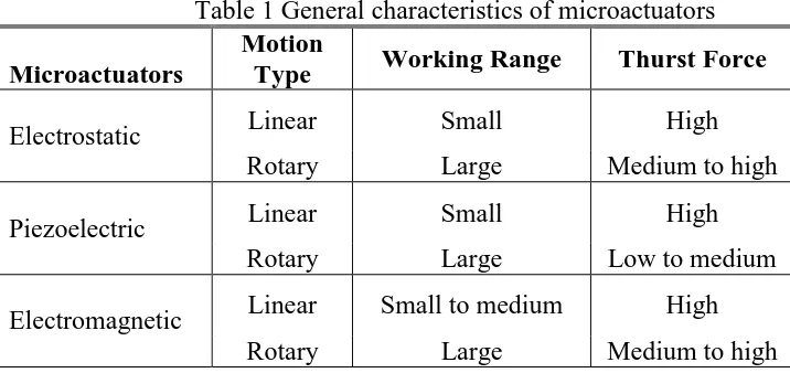
Nowadays, the growth of interest in Micro Electro Mechanical System (MEMS) is increasing rapidly. MEMS consists of micromechanisms such as microstructures, microactuators and microsensors. Microactuator is a subset of microelectromechanical systems (MEMS) that convert electrical energy to mechanical energy. With advance technologies in microfabrication for MEMS, an efficient and reliable microactuator can be built for various microsystems. Microactuators can be used for development in biotechnology, medicine, communication and inertial sensing. Several types of microactuators have been studied widely such as the electrostatic microactuator, piezoelectric microactuator and electromagnetic microactuator [1,2]. Table 1 shows the comparison of the genereal characteristics of the microactuators, which consist of two motion drives, i.e (i) linear motion and (ii) rotary motion. From Table 1, the rotary actuator able to apply to a large working range compared to the linear actuator. In comparison, both electrostatic and electromagnetic actuator able to generate a better thurst force compared to the piezoelectric actuator. Although electromagnetic actuators are the most widely used, electrostatic actuators have some advantages in terms of their heat production and material availability compared with electromagnetic actuators [3]. In addition, unlike piezoelectric actuators, electrostatic actuators are able to transmit power without mechanical contact and do not require hinges, which make the systems complex. Previously, various types of electrostatic actuators have been designed which show good performances.
Table 1 General characteristics of microactuators
Microactuators
Motion
Type Working Range Thurst Force
Electrostatic Linear Small High
Rotary Large Medium to high
Piezoelectric Linear Small High
Rotary Large Low to medium
Electromagnetic Linear Small to medium High
Rotary Large Medium to high
Rotary Motion Electrostatic Microactuator
Actuation Principle
A rotary motion microactuator in general consists of a rotor and a stator, both having several number of teeth-like electrodes. During operation, the rotor electrodes are grounded and the stator electrodes are grouped in three different electrical phases that are symmetrically distributed around the rotor. Each phase can be activated independently. At the initial position, the electrodes of the first phase are perfectly aligned with the opposite electrodes of the rotor side. By applying voltage differences on one of the misaligned phases, electrostatic thrust force can be generated. Clockwise or counter-clockwise stepwise motion can be achieved by changing the phase sequences [3].
Design Structures: Side-Driven and Bottom-Driven
Fig. 1 shows the three-dimensional view of two designs; (a) Side-Driven Electrostatic Microctuator and (b) Bottom-Driven Electrostatic Microctuator which comprise of 12 stators and 16 poles rotor [4]. The rotor of the Side-Driven is mounted inside the stator. However for the Bottom-Driven, the stator is mounted directly above the stator, which increases the thickness of the actuator. Both designs function as a three-phase microactuator. The diameter of rotor is 1.4mm and the gap between the stator and rotor is 2µm for both designs. The initial dimensions of the two designs are listed in Table 2. The operation of these microactuators relies on the electrical energy stored in the variable capacitances formed between the poles of the rotor and the stator. The stator poles are connected in an alternative sequence with three electrical phases; each phase activates a group of stator independently. When a phase is activated, a voltage difference between the corresponding stator poles and the opposite rotor poles generates an electrostatic force which realign the poles of rotor with the activated stator poles.
(a) Side-Driven Electrostatic Microctuator (b) Bottom-Driven Electrostatic Microctuator
Force Characteristics and Design Optimization using FEM Analysis
In order to optimize the design parameter’s of the rotary electrostatic microactuator, ANSYS Maxwell 3D was used to analyse the electrostatic thrust force of both designs. Simulations are done by varying the actuator’s parameters using Finite Element Method (FEM) analysis. The paramters varied are (i) actuator size; (ii) actuator thickness and (iii) actuator teeth ratio.
Table 2 Initial design parameters
Parameter Symbol Value
Rotor radius r 700 µm
Pole width (Side-Driven) w1 50 µm
Pole width (Bottom-Driven) w2 500 µm
Gap (rotor/stator) d 2 µm
No. of active poles per phase n 4
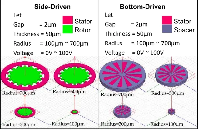
Varying Actuator Size
The size of both actuators were set to seven values; i.e 100m to 700m respectively, whilst the gap
between the stator and the rotor, teeth ratio and thickness of actuator is fixed to 2m, 16:12 and 50m,
respectively. The FEM analysis was implemented by applying input voltages to the actuator. Fig. 2 shows both the structures of the Side-Driven and Bottom-Driven with different sizes. Fig. 3 shows the relationship between the size of actuator, applied voltage and the generated electrostatic force. From Fig. 3, it can be depicted that, as the size of actuators decreases, the overlapping area between the rotor and the stator electrodes will also decreased, which results in lower thrust force. By comparing Fig. 3 (a) and (b), the electrostatic force of Bottom-Driven Electrostatic Microctuator is higher than the electrostatic force of Side-Driven Electrostatic Microctuator because of the area overlapping of Bottom-Driven actuator is larger than area overlapping of Side-Driven actuator. Therefore, it can be concluded that electrostatic force depends on the overlapping area between the stator and the rotor electrodes.
(a) Side-Driven Electrostatic Microctuator (b) Bottom-Driven Electrostatic Microctuator
Fig. 2: Structure comparison between the side-driven and bottom-driven microactuator, when the size is varied.
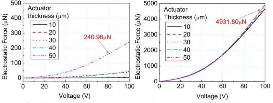
Varying Actuator Thickness
The thickness of both actuators were set to five values; i.e 10m to 50m respectively, whilst the gap
between the stator and the rotor, teeth ratio and size of actuator is fixed to 2m, 16:12 and 700m,
electrostatic force produced because the area overlapping depends the actuator’s thickness. However, it can be depicted that changing the thickness of bottom-drive actuator does not affect the electrostatic force because the area overlapping of bottom-drive actuator does not depend on the thickness of actuator. By comparison, the Bottom-Driven actuaotr produced greater electrostatic force than Side-Driven actuator although manipulating the thickness of actuator does not significantly affect the generated electrostatic force.
(a) Side-Driven Electrostatic Microctuator (b) Bottom-Driven Electrostatic Microctuator
Fig. 3: Comparison of the generated thrust force between the two designs when the size is varied, evaluated with different input voltages.
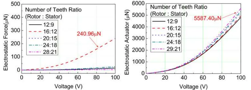
Varying Actuator Teeth Ratio
The teeth ratio of both actuators were set to five values; i.e 12:9, 16:12, 20:15, 24:18 and 28:21 respectively, whilst the gap between the stator and the rotor, thickness and size of actuator is fixed to
2m, 50m and 700m, respectively. Fig. 5 shows the relationship between the teeth ratio of actuator,
applied voltage and the generated electrostatic force. From Fig. 5 (a) and (b), the results show that almost all the ratio has the almost similar electrostatic force value. This maybe due to increase number of teeth, thus increasing the overlapping area between stator and rotor electrode. However, simultaneously the distance travel per step input will be decreased. Therefore based on these results, it is concluded that the electrostatic force tends to remain the same when the teeth ratio is increased.
(a) Side-Driven Electrostatic Microctuator (b) Bottom-Driven Electrostatic Microctuator
(a) Side-Driven Electrostatic Microctuator (b) Bottom-Driven Electrostatic Microctuator
Fig.5: Comparison of the generated thrust force between the two designs when the teeth ratio is varied, evaluated with different input voltages.
Conclusion
The overall results show that in terms of the generated electrostatic thrust force, the Bottom-Driven microactuator has more advantages compared to the Side-Driven microactuator. Based on the FEM analysis results, both the size and thickness affect the generated electrostatic force of Side-Driven Microactuator significantly, however the thickness does not affect the performances of Bottom-Drive Microactuator. As a conclusion based on Table 3, the FEM analysis results show that the Bottom-Drive Electrostatic
Microactuator exhibit greater thrust force, 4931.80N compared to the Side-Drive Electrostatic
Microactuator, 240.96N; when the actuator’s radius is 700m, thickness is 50m, gap between the stator
and rotor is 2m and the teeth ratio is 16:12.
Table 3 FEM analysis results of the rotary motion designs
Type Characteristics
Highest force 240.96µN 240.96µN 240.96µN
Bottom-Driven
Parameters 700µm 50µm 16:12
Highest force 4931.8µN 4931.8µN 5587.4µN
Acknowledgement
This research and publication is supported by Universiti Teknikal Malaysia Melaka (UTeM) Short Term Grant no. PJP/2013/FKE(4C)/S01170. Authors are grateful to UTeM for supporting the research.
References
[1] M. Karpelson, G.-Y. Wei, and R. J. Wood; “A review of actuation and power electronics options for
flapping-wing robotic insects”, IEEE International Conference on Robotics and Automation, Pasadena,
CA, USA, pp. 779-786 (2008).
[2] Niino T, Egawa S, Higuchi T.; ”Dual excitation multiphase electrostatic drive”, Proceeding of the
Industry Application Society Annual Meeting. pp.1318–25 (1995).
[3] E. Sarajlic, C. Yamahata, M. Cordero, L. Jalabert, T. Iizuka, H. Fujita; “Single mask 3-phase
electrostatic rotary stepper micromotor“, International Conference of Solid-State Sensors, Actuators and
Microsystems, pp. 1505 – 1508 (2009).
[4] N.Ghalichechian, A. Modafe, M. I.Beyaz, R.Ghodssi; “Design, fabrication and characterization of a
rotary micromotor dupported on microball bearings”, Journal of Microelectromechanical Systems, Vol.