DOI: 10.12928/TELKOMNIKA.v11i3.1090 489
H-Bridge based Five-Level Current-Source Inverter for
Grid Connected Photovoltaic Power Conditioner
Suroso*1, Daru Tri Nugroho1,Toshihiko Noguchi2 1
Department of Electrical Engineering, Jenderal Soedirman University, Indonesia
2Department of Electrical and Electronics Engineering, Shizuoka University, Japan
*Corresponding author, e-mail: [email protected], [email protected]
Abstrak
Makalah ini menyajikan suatu aplikasi rangkaian baru dari inverter jenis sumber arus lima-level yang digunakan pada sistem photovoltaik yang terhubung dengan jala-jala listrik. Dalam konfigurasi multilevel inverter ini, sebuah H-bridge inverter sumber arus dihubungkan dengan modul arus DC yang bekerja untuk membangkitkan gelombang arus lima-level. Keunggulan dari konfigurasi inverter ini adalah jumlah dari piranti penyaklaran, dan rugi-rugi induktor dapat dikurangi. Konfigurasi dari rangkaian inverter lima-level diuji untuk aplikasi pada sistem photovoltaik yang terhubung dengan jala-jala listrik dengan simulasi komputer menggunakan software PSIM. Hasil pengujian eksperimen dari inverter lima-level juga disajikan. Dari hasil pengujian didapat bahwa inverter yang telah dirancang mampu bekerja dengan baik membangkitkan gelombang arus lima-level dan menginjeksikan arus sinusoidal ke jala-jala listrik dengan nilai distorsi harmonisa yang kecil serta faktor daya bernilai satu.
Kata kunci: inverter, lima-level, jala-jala listrik, photovoltaic, harmonisa
Abstract
This paper presents an application of a new circuit configuration of H-bridge based five-level current-source inverter (CSI) used for grid connected photovoltaics system. In this topology, the intermediate level currents of the five-level current waveform are generated by connecting DC current module to the H-bridge CSI. Some new features can be derived using this new topology such as reducing the switching power device count, and reducing the inductor conduction losses of the inverter. The proposed five-level CSI is tested for grid connected photovoltaic system through computer simulation using PSIM software. Furthermore, the experimental test results of the proposed five-level CSI are presented. The results show that the inverter works properly generating a five-level current waveform and injecting a sinusoidal current into power grid with less harmonics distortion and with unity power factor operation.
Keywords: inverter, five-level, power grid, photovoltaic, harmonics
1. Introduction
Basically, the multilevel inverter topologies can be categorized into multilevel voltage source inverters (VSI) and their dual circuits, i.e., multilevel current source inverters (CSI) [1, 2]. The multilevel VSI has DC voltage power sources and delivers multilevel AC voltage waveforms to the load, while the multilevel CSI produces predetermined multilevel AC current waveforms from a single or some DC current sources. Because of its high impedance DC power source, the multilevel CSI features high capability of short-circuit protection. The multilevel inverters have various advantages compared with the conventional two-level inverters such as lower dv/dt or lower di/dt, and less harmonics content of the output waveforms [3-8].
generated AC current, which is indispensable in the VSI. The output current of CSI is less dictated by the grid voltage [11]. Moreover, the discrete diodes connected in series with the power switches to obtain unidirectional power switches required in the CSI are unnecessary because reverse-blocking IGBTs are currently available [12, 13].
2. Proposed H-Bridge based Five-Level Current-Source Inverter 2.1. Circuit Configuration and Operation Principle
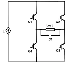
Figure 1 shows the basic configuration of an H-bridge CSI. This inverter works generating a three-level current waveform, i.e. level +I, 0 and –I, as listed in the Table 1. Figure 2 shows the configuration of the proposed DC current-module. The current-module is composed by a DC current source, unidirectional controlled power switch and a connecting diode. The newly proposed configuration of the five-level CSI is obtained by connecting the H-Bridge CSI and a single DC current-module as shown in Figure 3. The DC current-module work generating the intermediate level currents for five-level output current waveform generation. The amplitudes of the parallel DC current sources in the proposed five-level CSI are I/2, which is half of the amplitude of the DC current source in the three-level H-Bridge CSI. Furthermore, all DC current sources are connected at the same point, which make the isolated DC current sources are no longer necessary in this topology [14, 15]. The DC current source generation will be explained in more detail in the next section. The switching state combinations required to generate a five-level current waveform are listed in Table 2.
Figure 1. Configuration of H-bridge CSI Figure 2. DC current-module
Figure 3. Proposed H-bridge based five-level CSI
Table 1. Operation modes of H-bridge CSI
Q1 Q2 Q3 Q4 Output Current
1 0 1 0 +I
1 0 0 1 0
0 1 1 0 0
0 1 0 1 -I
Table 2. Switching States of proposed five-level CSI
Q1 Q2 Q3 Q4 Q5 Output
1 0 1 0 0 +I
1 0 1 0 1 +I/2
1 0 0 1 1 0
0 1 0 1 1 -I/2
0 1 0 1 0 -I
2.2. DC Current Generation Circuits
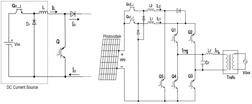
power switch (Q), a smoothing inductor (L) and a free wheeling diode (DF). The switch functions regulating the DC current flowing through the smoothing inductor, and reducing the smoothing inductor size, owing to the high-switching-frequency operation. Free-wheeling diode DF is used to keep continuous current flowing through the smoothing inductor [15]. Figure 5 shows the configuration of a five-level CSI operates as a grid connected inverter. The inverter is connected to the power grid through a power transformer as galvanic isolation between inverter and power grid. The five-level CSI needs only a single DC voltage source (VPV) connected to the circuits to obtain two DC current-sources. The DC voltage source in this paper is a photovoltaic system.
Figure 4. The circuit of DC current
generation Figure 5. The H-bridge based five-level CSI for power grid connection of photovoltaic
2.3. Current Controller and PWM Modulation Strategy
The proportional integral (PI) controllers are applied to control the DC currents flowing through the inductors L1 and L2. The amplitude of the smoothing inductor current is kept at 50 % of the peak value of the five-level current waveform. The switching gate signals of the DC current generation circuits are generated by comparing the current error signals after passing through the PI controller with a triangular waveform. These signals are used to adjust the operation of the DC-current generation circuit to achieve the balanced DC current sources IL1
and IL2.
In this paper, a level-shifted triangle carrier based sinusoidal PWM technique is employed to generate the gate signals for the five-level CSI power switches to obtain the PWM current waveforms. All carrier waveforms are in phase with each other at the same frequency. The frequency of the modulated sinusoidal signal (a reference signal) determines the fundamental frequency of the inverter’s output current waveform, while the frequency of triangular carrier waveforms gives the switching frequency of the five-level CSI power switches [13-15]. Figure 6 shows an overall control diagram of the proposed five-level CSI including the DC current generation circuit and inverter controllers.
3. Results and Analysis
In order to test the proper operation of the proposed system, the grid connected five-level CSI configuration shown in Figure 5 is tested through computer simulations with a PSIM software. The test parameters are listed in Table 3. Figure 7 shows the computer simulation result of the proposed five-level CSI when the inverter is connected with a pure sinusoidal power grid voltage, where the five-level PWM current, the current injected into the power-grid (Iinv), the grid voltage (VGrid), and the current flowing through the smoothing inductors (IL1 and
sT
1 1
sT
1
1
Figure 6. Control diagram of the inverter
Figure 7. Test result when the inverter is connected with a pure sinusoidal power grid
voltage
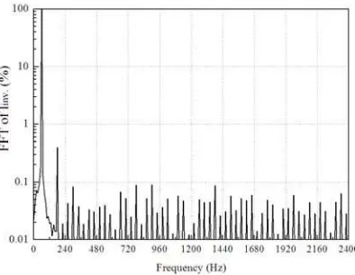
Figure 8. Harmonic spectra of inverter’s output current
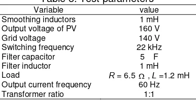
Table 3. Test parameters
Variable value
Smoothing inductors 1 mH
Output voltage of PV 160 V
Grid voltage 140 V
Switching frequency 22 kHz
Filter capacitor 5 F
Filter inductor 1 mH
Load R = 6.5 , L =1.2 mH
Output current frequency 60 Hz
Transformer ratio 1:1
The amplitudes of the smoothing inductor currents are well balanced for both smoothing inductors IL1, IL2 at 50 % of the output current peak value. Figure 8 shows the harmonic spectra of the current injected by the inverter (Iinv). All of harmonic components are less than 1%. Figure 9 shows the harmonic spectra the power grid voltage.
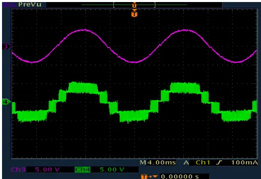
Furthermore, Figure 10 shows the computer simulation results when the inverter is connected to a distorted power grid. The harmonic spectra of the current injected by the inverter into the power grid (Iinv), and the power grid voltage (VGrid) are shown in Figure 11 and Figure 12, respectively. Figure 13 presents the load current and five-level current waveforms obtained from the experimental test. The results show the proper operation of the proposed H-bridge based five-level CSI as a grid connected inverter.
Figure 10. Test result when the inverter is connected with a distorted power grid voltage
Figure 11. Harmonic spectra of the inverter’s output current
Figure 13. Experimental test result of the load current and five-level current waveforms
4. Conclusion
In this paper an application of a new circuit configuration of five-level CSI applying an H-bridge and DC current-module has been presented. Using the proposed five-level CSI, a low distortion of output current with fewer power switches, and smaller inductors can be achieved. The inverter is proposed to be used as grid-connected photovoltaic power conditioner. The proposed system has been tested through computer simulations. The results show the proper operation of the proposed five-level CSI as a grid connected inverter injecting a sinusoidal output current into the power grid with a unity power factor operation.
References
[1] J Rodiguez, JS Lai, FZ Peng. Multilevel inverter: a survey of topologies, controls, and application.
IEEE Transactions on Industrial Electronics. 2002; 49(4): 724-738.
[2] PG Barbosa, HAC Braga, MC Barbosa, EC Teixeria. Boost current multilevel inverter and its application on single phase grid connected photovoltaic system. IEEE Transactions on Power Electronics. 2006; 21(4): 1116-1124.
[3] RTH Li, HS Chung, TKM Chan. An active modulation technique for single-phase grid connected CSI.
IEEE Transactions on Power Electronics. 2007; 22(4): 1373-1380.
[4] C Klumpner, F Blaajerg. Using reverse blocking IGBTs in power converters for adjustable-speed drives. IEEE Transactions on Inductry Applications. 2006; 42(3): 807-816.
[5] ZH Bai, ZC Zhang. Conformation of multilevel current source converter topologies using the duality principle. IEEE Transactions on Power Electronics. 2008; 23(5): 2260-2267.
[6] S Kwak, HA Toliyat. Multilevel converter topology using two types of current-source inverters. IEEE Transactions on Inductry Applications. 2006; 42(6): 1558-1564.
[7] D Xu, NR Zargari, B Wu, J Wiseman, B Yuwen, S Rizzo. A medium voltage AC drive with parallel current source inverters for high power application. Proceeding of IEEE PESC2005. 2005; 2277-2283. [8] FLM Antunes, AC Braga, I Barbi. Application of a generalized current Multilevel cell to current source
inverters. IEEE Transactions on Power Electronics. 1999; 46(1): 31-38.
[9] JY Bao, DG Holmes, ZH Bai, ZC Zhang, DH Xu. PWM control of a 5-level single-phase current-source inverter with controlled intermediate DC link current. Proceeding of IEEE PESC2006. 2006: 1633-1638.
[10] BP McGrath, DG Holmes. Natural current Balancing of Multicell Current Source Inverter. IEEE Transactions on Power Electronic. 2008; 23(3): 1239-1246.
[11] B Wu. High Power Converters and AC Drives. Wiley-IEEE Press. 2006.
[12] Suroso, T Noguchi. Five-Level Common-Emitter Inverter using Reverse-Blocking IGBTs.
TELKOMNIKA. 2012; 10(1): 25-32.
[13] Suroso, T Noguchi. Common-Emitter Topology of Multilevel current-Source Pulse Width Modulation Inverter with Chopper based DC-Current Sources. IET Power Electronics. 2011; 4(7): 759-766. [14] Suroso, T Noguchi. New H-Bridge Multilevel Current-Source PWM Inverter with Reduced Switching
Device Count. Proceeding of IEEE IPEC. 2010: 1228-1235.