DOI: 10.12928/TELKOMNIKA.v14i3A.4431 224
X-ray Imaging Technology Application in Fuxin Switch
Equipment Test
Jianjun Wu*, Yupeng Wang, Qing Ye, Baichao Su
Fuxin Power Supply Company of State Grid Liaoning Power Co., Ltd., Fuxin City, Liaoning Province, 123000, China
*Corresponding author, e-mail: [email protected]
Abstract
Since the equipment transmission parts of combination electric appliance in transformer substation are located in the shell, when an internal fault appears, the traditional charged test method only can preliminarily determine the defective position and types, but cannot directly shows the internal defects of the equipment. The Fuxin Company actively introduced X-ray CR imaging test technology and applied it to imaging test of switch equipment, achieved the visual inspection of equipment internal condition without disassembly of equipment and influence on the normal operation condition, and more accurately judged the defect nature, position and size. Practice results show that as a new method of switch devices testing, the X-ray imaging test can successfully achieve the visual and mobile NDT.
Keywords: Switch equipment; X-ray; DR imaging; Test; Defect
Copyright © 2016 Universitas Ahmad Dahlan. All rights reserved.
1. Introduction
With the continuous development of power grid construction, the types of switch devices in Fuxin power grid substation in Liaoning province is also growing. More than 110 KV switch equipment mainly include the porcelain pole breaker, tank type breaker and GIS equipment. The running state plays a crucial role on the safety and stability of the power grid. Once the switch devices have a fault, the fault not only endangers the power grid safety, but also takes a long time to repair and causes huge economic losses. Therefore, it is very important to timely grasp the running state.
In 2012, the Fuxin Company applied the X-ray DR digital imaging technology to the test of switch devices through the long term loan of Israel VIDISCO amorphous silicon of digital radiographic testing system. The pixel size is 0.127mm, and the imaging is 210mm*210mm. It is equipped with 300kV surge X-ray machine and the 270kV pulse X-ray machine.
2. X-Ray DR Imaging System 2.1. X-Ray Imaging Principle
X-ray digital imaging technology is a new X-ray nondestructive testing technology that is developed in recent years. Compared with the traditional film type of test method, it is characterized of fast test speed, strong portability, high test sensitivity, test results managed easily, and small field radiation, etc. After X-ray passes through the tested object, the ray detector converts the X-ray test signals into digital signals that are received by the computer to form the digital image and stored in the computer according to certain format. The black level of images depends on the radiation exposure (also called exposure). Since the ray intensity of defect parts and good parts is different, image corresponding parts will have the difference of black degree. The blackness difference of image adjacent area is defined as “contrast ratio” [1]. According to the different shapes of images formed by the contrast ratio, experimenters can judge the defects of equipment to reach the goal of defect state evaluation.
2.2. X-Ray DR Imaging System
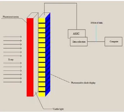
The industrial X-ray imaging principle is the same as the principle of X-ray, CT and security system. When penetrating the different objects, X-ray interacts with the matter. Due to the absorption and scattering, intensity is changed. The photosensitive material (IP plate) receives the signal of intensity change to form the common images [2, 3] through the signal processing. A complete set of test system, which is used in the test of switch devices, includes the radiation source, sensitive plate (IP plate), CR scanner, image display system (including the software of image processing analysis), the on-site mobile scaffold, mobile workstation, etc. The specific process sees the principle Figure 1. First connect the connecting line between components, set the test parameters through the control box. X-ray from the ray generator penetrates the tested part. After the part is subject to the sensitization of the IP imaging plate directly facing the back of the equipment, it is scanned by CR scanner to form the digital image.
Figure 1. X-ray DR imaging principle
3. The Typical Defects of Switch Devices
unit-times. The average failure rate in five years was 0.060 unit-times/hundred•unit-year. The cause of faults mainly includes the insulation failure, damage to the parts, body leakage, fail-to-break and rejecting closing, etc. The faults mainly occur in the transmission component parts.
The partial discharge analysis and the gas composition test have been commonly used in the fault test of switch devices. However, due to the difference of the structure and fault positions of different switch devices, the current test method cannot fully determine whether there are defects in equipment, and cannot intuitively and visually determine the defect position in the equipment. The X-ray digital imaging technology can achieve the visual imaging of internal structure of the equipment for the suspicious air chamber or positions of switch devices.
4. Results and Analysis
Using the X-ray CR imaging test can conduct the visual test without disassembly of equipment and influence on the normal operation, gain the intuitive and accurate digital imaging in the equipment. Combined with other test methods, it can achieve the effective and reliable test of the equipment. The concrete practice case is as follows.
4.1. The State Test of Post Insulator of Composite Apparatus
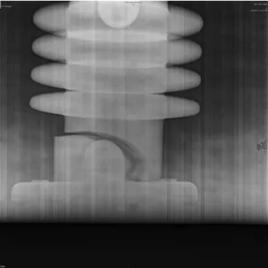
The composite apparatus in certain transformer substation had the fault of electric discharge during operation led to exit run. After electrical signal analysis, it is believed that there is a possibility of the post insulator failure of circuit breaker. In order to verify the condition of the failure point, adopt the digital ray for transillumination. X-ray generator directly faces the circuit breaker body and is parallel to the arc extinguishing chamber of the circuit breaker. The nylon rope is adopted to fix the DR imaging plate. The horizontal distance between the X-ray generator and the main transmission shaft pin is 600mm. The voltage of the generator is set as 250kV, and the transillumination time is 10 seconds [4]. The test result is shown in the Figure 2. Imaging results show that the post insulator has the phenomenon of obvious fracture [5, 6].
Figure 2. The schematic diagram of post insulator by X-ray imaging test
4.2. Contact Defect Test of Composite Apparatus
4.3. Incomplete Fusion Defect Test of Composite Apparatus Cylinder
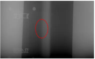
When the composite apparatus cylinder adopts the automatic welding for assembly, the incomplete fusion defects often occur. Since the internal surface of the composite apparatus is attached with the coating for supplementary insulation and the scene processing is trouble with the great risk, the problems should be solved in the manufacturer. For the welding of longitudinal seam and circumferential seam, the manufacturer adopts the digital ray to conduct100% detection. For fillet weld, conduct 100% surface detection. Using the X-ray imaging not only intuitively shows the internal state of equipment, but also saves the precious time for putting equipment in service.
Figure 3. The X-ray imaging result under the condition of isolating switch contact travel to the end
The ray test rate for crack defects is poor, and there is the crack test angle problem. After testing, DR crack test angle can achieve 30°, which is much better than film imaging. In the detecting process, we set the included angle of the same welding seam as 60° and transillumination two times, which can effectively improve the test rate of the incomplete fusion defect.
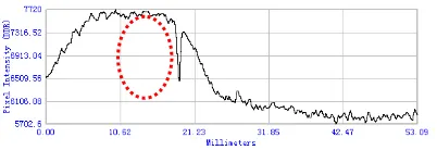
Figure 5. Gray level contrast figure of incomplete fusion defect
5. Conclusion
1. X-ray imaging test can achieve the intuitive display of defective parts of the equipment through take pictures of equipment internal structure, provide the reliable basis for equipment diagnosis, add a powerful test means for the live dete4ction of substation equipment, avoid the losses arisen from the blind disassembly of equipment, and save the manpower and time.
2. Integrate the X-ray imaging test with the SF6 decomposition product test, ultrasonic wave partial discharge, superhigh frequency partial discharge and other test methods to achieve the linkage between specialties and to help to improve the efficiency of fault finding and defects analysis.
3. The Fuxin Company applies the X-ray imaging test to the test of composite apparatus, which is a bold attempt of the X-ray imaging technology and provides the reliable basis for equipment diagnosis.
References
[1] Curkendall DW, Mareynolds SR. A Simplified Approach for Determining the Information Content of Radio Tracking Data. Journal of Spacecraft. 1969; 6 (5): 520-525.
[2] Wang DD, Wei J, Yu H, etc. GIS Equipment NDT by X-ray Digital Imaging. Yunnan Electric Power Technology. 2002; 40(2): 8-10.
[3] Liu Y, Zhao JP, Yan B, etc. X-ray Digital Imaging Application in GIS Equipment Test. Xinjiang Power Technology. 2013; 117(2): 21-23.
[4] Rad AE, Rahim MSM, Norouzi A. Digital Dental X-Ray Image Segmentation and Feature Extraction.
TELKOMNIKA Indonesian Journal of Electrical Engineering. 2013; 11(6): 3109-3114.
[5] Guo T, Wang DD, Yu H, etc. The Choice of Focal Length in X-ray Visual Test of GIS Equipment.
China Southern Power Grid Technology. 2012; 6(3): 110-114.
[6] Hou H, Wang M, Wang X. R-L-MS-L Filter Function for CT Image Reconstruction. TELKOMNIKA Telecommunication Computing Electronics and Control. 2016; 14(1): 195-202.
[7] Manikandan J, Celin CS, Gayathri VM. A Document Imaging Technique for Implementing Electronic Loan Approval Process. Indonesian Journal of Electrical Engineering and Informatics. 2015; 3(2): 109-114.