1
CHAPTER I
1.1INTRODUCTION
This paper is focused on the finding the actual value of the engine mounting stiffness KS and damping constant CD of the Proto n Gen. 2. In this case Proton Gen. 2 is using in-line four cylinders engine coupled with 4 speeds automatic transmission engine.
For the analysis purposes, mathematical equation was developed which accurately describe the motion of the engine on selected condition, starting from idle condition, 1500 RPM condition and up until 4000 RPM condition. Mathematical equation is crucial for developing the model in MATLAB 6.5 computer programming. Mathematical model for engine mounting system is based on the full car model equation which describes the pitch, roll, and vertical acceleration of the engine on the chassis.
2
1.2OBJECTIVE OF STUDY
Main objective of this research is to gather vibration amplitude value by experiment and simulation in computer software, MATLAB 6.5. This vibration generates by engine and gearbox unit will be transfer to the Proton Gen. 2 chassis via engine and gearbox mounting system.
The goal of the research is to:
a. find rate of spring stiffness, KS and damping constant CD of Proton Gen. 2 by comparing data acquire from experiment and simulation.
3
1.3PROBLEM STATEMENT
For over 100 years, comfort in road vehicles has been linked to the introduction of passive components that isolate passenger compartments from mechanical vibration. Near-optimal performance has been achieved by years of experimentation and testing, careful selection and shaping of individual component characteristics, and the development of ingenious mechanisms intended to minimize the effect of inherent design constraints associated with passive systems.
Lighter vehicles are typically more susceptible to noise and vibrations. Furthermore, as vehicle age, their vibration and noise level increase. Today, noise and vibration control have become a prime consideration in the general manufacturing industry, and more specifically the automotive industries. Increased attention to product quality has brought the issue of “psycho-acoustics” to the transportation industry. Thus within recent years, there has been a major increase of effort in the design of noise and vibration characteristics of vehicles that would better appeal to the occupants.
Usually passive mounting system made of rubber material that has been constrained to certain parameters. As an example, in order to limit the movement of the engine and gearbox unit, mounting system desired to have very stiff rubber. However to minimize transmission of engine and gearbox vibration into passenger compartment, a very soft mount is required. Both specifications contradict to each other making only one of the characteristic needs to be sacrifice.
4
broad-band, then typical passive vibration controllers would not be effective. This is a major shortcoming of the passive vibration control technique.
Current practice for reducing noise levels is to use such passive sound absorbing materials as fiber linings, acoustic foams and rubber material. Such a thick sound treatment may not provide more than 5dB noise reduction. Therefore, such passive noise treatments at low frequencies are physically unrealizable.
5
1.4SCOPE
For this research, it will be focused to study how vibration originated from engine and gearbox unit will be transmit to the vehicle chassis. As we noticed, the only physical connection between engine and gearbox unit to vehicle chassis is mounting system. Common practice in the automotive industry is to apply passive mounting system due to the low cost. Basic design of passive mounting system will be study to investigate the weakness of this unit.
The behavior of the passive engine mounting will be study by experimental method. Vibration sensor unit called accelerometer will be placed in a couple. One unit of sensor will be place on the engine and another one will be place on the chassis. Both of the sensors will be place near to the engine mounting point, labeled as point A, B, C, and D. Total of 8 unit of sensor will be place according to the specific point.
6
CHAPTER II
BACKGROUND
2.0 LITERATURE REVIEW
In automotive system, three dominant source of vibration is drive train, tire and wind. The engine produces broad band vibration resulting from combustion processes. The engine driven accessories and the transmission generate vibration as a result of their unbalances. The tires and suspension generate vibration as a result of tire tread interaction with the road surface. Wind noise results from viscous shearing in the boundary layer of air surrounding the vehicle. However, this research is more focused on chassis vibration induce by engine and power transmission component especially vibration that causes from unbalanced rotating mass.
Previous research held by other party including researcher from School of Automotive Engineering, University of Ulsan, Tokyo Institute of Technology, and Massachusetts Institute of Technology (MIT) are more focused on the designing new engine mounting system controlled by hydraulic and actuator. Some of them are focused on the automotive noise and vibration for the whole of the vehicle and not specifically on the engine mounting.
7
Itsuro Kajiwara and Akio Nagamatsu from Tokyo institute of Technology, Japan investigated the active and adaptive control of engine mounting as a way to overcoming the weakness of passive engine mounting. Their research covered mathematic formulation of active engine mounting and engine mount control design.
Lisa A. Sievers and Andreas H. Flotow from Department of Aeronautics and Astronautics study on active control of engine mount to enhance the quality of passenger compartment in the term of comfort. They also proposed three control schemes for actively controlling engine mounts.
For my research, it is more focused on the behavior of the passive engine mounting system under the specific condition. As example, there will be an experiment held to determine the vibration produce by engine and power transmission unit at idle speed and high speed. Accelerometer will be place at the engine and power transmission unit and at the chassis. These sensors detect the amplitude of vibration produce by engine and power transmission unit and the amplitude of vibration transmitted to the chassis of Proton Gen. 2 via passive mounting system.
Full car model in mathematical formulation with the formulation of the engine and power transmission mounting system have been developed by using computer software simulation, Matlab. The final goal of this research is to find the right value of spring stiffness K and damping constant D used by engine mounting system of Proton Gen. 2. Data obtained by this research will hand over to the researcher who interested to further the research in the active control of engine mounting system.
For this research, the main function of the engine and gearbox mounting system has been investigated thoroughly. The basic design, the main function of this mounting is to:
a. to attached engine and gearbox unit to the vehicle chassis b. to absorb engine noise and vibration
8
Engine mounts must be stiff enough to hold the engine and gearbox, and at the same time soft to absorb vibration. Also engine mounts must be flexible to permit frame to twist.
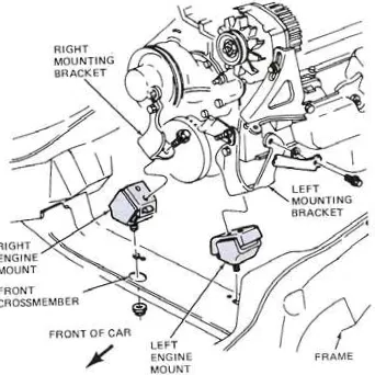
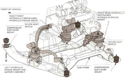
In practice, most of the manufacturer usually attached the engine and gearbox to the chassis according to the specific needs. Which axle would drive the vehicle will determine the layout of the engine and gearbox unit in the engine bay. If rear axle was selected to drive the vehicle, engine and gearbox unit will be arranged in longitudinal arrangement. But if front axle was selected, engine and gearbox unit will be arranged in transverse arrangement.
[image:19.612.185.369.273.446.2]
Figure 1. Gearbox mounting in longitudinal arrangement
[image:19.612.171.342.509.680.2]9
10
Picture 1. Engine mounting at the left side of engine block
11
Picture 3.Engine mounting, located at the bottom of engine
12
CHAPTER V
3.0 REASEARCH METHODOLOGY
COLLECT DATA FOR QUARTER- FULL-CAR
MODEL
BUILDING THE SIMULINK BLOCK DIAGRAM USING MATLAB
SIMULATION
IMPROVEMENT OF CURRENT SYSTEM SOFTWARE SELECTION
SET PARAMETER START
13
3.1 Mathematical Formulation
Mathematical model was develop is based on the equation that have been developed is focused on the reaction movement of the engine itself on the axis and the reaction movement of the chassis imposed by vibration developed by engine. Both chassis and engine would pitch, roll and accelerate on the vertical axis.
For mathematical model, the idea is to assume the movement of the engine and chassis from the figure of the chassis and engine assembly. Chassis and engine were assumed to be rigid body of mass M1 and M2 respectively. The mass will be assume based on the real references.