UMPEDAC Postgraduate Srudents Renewable Energy Symposium (201
l)
PMSM Rotor
Speed and
Position Estimator
Mohamed
Azmi
Said,W.p.
Hew,N.A.
Rahim
IJM Power Energy Dedicated Advanced Centre (UMpEDAC)
Level 4, Engineering Tower, University of Malaya 50603 Kuala Lumpur
azmisaid @siswa.um.edu.my
Abstract
-
Estimation techniques have been developed for flux observer,rotor
position, and speed. The techniques have a common problem of the offsetin
voltage_sensor andcurrent-sensor
outputs
increasing
during
integration,
causinginstability. This paper describes uo
att"-pito
overcome theproblem through estimations of rotor posiiion and speed of a permanent magnet synchronous
motor
(pMSM)
by
three methods:with
cascaded low passfilter
(LpF),with
adaptive sensorless rotor flux observer, and with sliding mode observer(SMO). Simulation on Matlab/Simulink validaled the proposed
method.
The
advantages
and
drawbacks
of
eachimplementation are discussed.
Keywords - PMSM motor drives, sensorless, cascaded LpF, adaptive rotor flux obsemer, SMO.
I.
INTRoDUCTIONPermanent
magnet
synchronousmotor (PMSM)
ispopular for its high efficiency, high power density, very low inertia, and high
reliability. In
field_oriented control (FOC)or
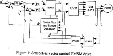
vector control schemes, continuous rotor information ismandatory.
To
ensurea
pMSM,s high
performance andprecise speed
control,
a
position encodeiis
required;it
senses and continuously feeds back both position and speed.
The position
encoder, though, imposes drawbackson
a system:it
is
costly,it
complicatescircuit,
is
sensitive tonoise,
and,
in
a
hostile
environment,is
fragile [1].
Its [image:1.588.46.265.541.650.2]absence
is
thus desired. Figure 1is
a
block dfagramof
a sensorless PMSM vector control drive.Figure 1: Sensorless vector control pMSM drive
_
Direct
torque control
(DTC)
[2] is
less parameter_ dependent, has fast dynamic response, and does not need amechanical
rotor position
sensorfor its
control
loop. Problems exist, though, namely,
drift in
stator_flux_linkage estimation, owing to measurement offset error andvaryiig
stator resistance.The
statorflux
linkagein
DTC
schemeis
estimated by integrating the difference between input voltage andvoltagl
drop across stator resistance:
)"r=vrt-R,
Rotor
flux
linkage1o&)
aad)r(k)at
thetth
sampting are calculated from stator voltage and current:)o(k)=1o,0_r*(V,u-r-R"ir)2"
e)
1o&)=
Xsrr,-t*(Verr,t-R,lr)4
(3)(l)
fi,at
+
l,tt=o
).,1k1
=
(4)From (5), rotor position
0
canbe calculated as:o=tan,(+9)
(5)\xD(k)
)
Rotor
position
angle0
dependson
estimated stator flux, whichis
determinedby
integrating the difference between input voltage and voltage drop across resistance, as Equation(l)
shows. There is an offset error produced by current andvoltage sensors. When stator
flux is
indirectly
integrated, any dc offset error is also integrated. This eventuallyiauses a largedrift in
statorflux
estimation. The offset error is non_periodical
and
unidirectional.It
can
not be
rectified
by calculation alone.It
must be overcomeby
some meansof
compensation (see Figure 7 for offset of
flux
locus).A.
Flw
estimator with a programmable cascaded low_passfilter
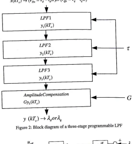
Figure
2 is a
block
diagram
of
the
three_stageprogrammable cascaded
LPF
[3].
The
discrete transfer characteristic of an LPF is:1T
=-
1-,-t
,'C(7-Z-t)
1+r' '
's'
T,
where 7
is
the samplingtime
and ? is
thetime
constant. The corresponding difference equation is:y(kT,)
=
{;tr"*(kT")
+
ly(kT,
-7"))
(1)(6)
Y
X
IIMPEDAC Postgraduate Students Renewable Energy Symposium (2011)
X
and
G
arefunctions offrequency or the rotor speed' at steady state, and are calculated as follows:(8)
(e)
where
n
is the number of filters cascaded' When the signalis
dc,
C
arrd
G
becomeinfinite'
thus thefilter
cannotoerform the
integration. Implementationof
the
cascaded[Fi
"ii"*t
,t eflrix
locus torimain
centered on theorigin'
The integration process however, requires knowledge of the
iJ,iJ
rtir"t
flui
position'If
the initial-position.informationi,
tt"
.orrt otterii
inaccurate' the motor mayinitially
rotatei,
tfr"
*ro.rg
direction. Cascaded LPF depends heavily too or,-rno,ot
i"qu"r"y. At
zero and
very
low
speeds' its implementation draws a disadvantage'B.
Adaptive sensorlessrotorflw
observerAdaptive
sensorlessrotor
flux
observercan
be
used to"uf"of*"
rotor
position andspeed
[4]'
From Equation (1)',h"
;;;;"t
oi
a PMSM motoris
givenby
the following statoivoltage and flux linkage equation:where
0
is
the
rotor
angle'Electrical
rotor
speed is expressed from mechanical rotor speed:y
(kT,) -+ ).oor).,Figure 2: Block diagram of a thrce-stage programmable LPF
[image:2.569.69.548.50.841.2] [image:2.569.320.547.82.329.2]Figure 3: Signal flow graph of the rotor angle observer
Figure 4: SPeed estimator
Figure
3
shows how thisis
obtainedby
a feedbackof
the estimated error .2,,,,",
- n*.
For a known magnitr'rdeof
the
permanentmagnet,
lr,uf
=
X* is
used'
Theobserver may then be seen as a rotor
field
angle estimator'At
zero and very low speeds, BEMF gives no informationof
,tL
n"iA"rgf".
i,t"*
principle is introduced to the situationby
impresslnga
currentin
the
direction
of
the
default"rti*ui"a
anlle.
rhe
currentthen
forcesthe
permanent
;rg*
t"
ai"g,
to that angle; this way, the estimated angleU""L"t
conlct
onlywitli
the error causedby friction
and load.Fizure
4
shows the signalflow
graphfor
therotor
speedesimator.
The
*gGtt)
uro"rt
solves
the
modulusproblem. The algorithm for the estimator then becomes:
+
=v"
-
R,i" +rrbr,,"r
-
l.rLtu
(16)i,
=
i,
-
L,i,
(17)+=v"
-
R,i,
clt
)',=L,ir+1,
^
^
ieA, =
Lu€'
49=r=p@*""h
(10)
( 11)
(t2)
(13)
Estimation
of 2,
requiresan
open
integrationof
thevoltage equation. The offset contained
in
the inputs hencemakes
the
outputdrift.
The offset
is
modeledas
)',
'Estimator for the rotor
flux
is:oi
= v,
-
R,i,
+
r)ou
(14)dt
l,
=
lr"it
(15)where fiouhas to be designed
in
a way that leadsto
aflux
estimate with constant amplitude
l2.l'
x(kT,) '+ (v* =uo'ioR)o'lva
=u,-
inR)AmplindeComPensation Gyr(kT")
(so')
tanl
-
I
\,J
a
IIMPEDAC Postgraduate Students Renewable Energy Symposium (2011)
0)=
d0,
;=
^
(20)C.
Sliding mode observerIn
sliding
mode,
the
observersare
insensitive
to parameoor variations and disturbance. Sliding mode observer has been presented for robust estimationofthe
state variableof
controlled objects[5-7].
Comparedwith
other methods,the
observeris
more robustto
operating conditions and parameter uncertainties [8].To
estimaterotor
position and angular
speedof
aPMSM, the motor
is
generally
modeledin
stationary reference frame. The angular speed and position information are ready to be extracted in this frame.In
stationarycondition,
aB
referenceframe can
be written as:with
/, >**
(r,;,lrrl).
The sliding hyper plane on the stator currenterrors
S=
,
=Vo ;rf
is aefinea according to thesliding mode observer theory. The system behavior can be examined
by
applying equivalent control method, when thesliding mode
occurs
after
a
finite time
intervalio=0and
lp=0.
From Equations (21) and(22),
Setting
=
0
glves:",(,-i)*
ei,-or)
(re)
t-+
o.l
t-trL)
A=l
:
*l''=l-',',i)
lu
-r)
(30)i*=0,
ip
di_ R. I
I;=
T'"
T""*T'"
dio
=-R,.-l r.*!r.
dt
LU
LP
LP
eo
= -2oo)"
sin(4
)
e o
=
),0a" cos(4
)io
=
o)"eO;
ip
=
A"eo
The sliding
mode
observer usesonly
motor equation. Its main equations are:di,__R" _1
I
/i\
,=-r,"
Tr"*-stgnud)
dfu R. I
1
/r\
i=-
,,0
Trr*-sign\iB)
*=-lr"-+",+l,ignQ.)
;=
-i,',
--1,"0
*1"*('o)
To
extract
eoand
e,
from the
corresponding equivalentcontrol values, a
low
passfilter
is usedwith
Zo,
zO
asfilter outputs:
u "n
o
=
(lrsign
(i,))"n
=
" o
u"qo
:
(lrrign
(i,)),,
=
,,
zo(t)
= eoQ) +
A,
(/)
zo1)=eoU)+L"(t)
(2t)
(22) (23) (24)
(2s)
elechical
(26) (27)
(28)
(2e)
(3 1)
(32)
(33)
(34) The motor speed changes slowly,
implying
that
A =
0
,the model for the induced back EMF is:
where
l,
is
constant observergain,
and io
=
io
-
io
,ip
=
tf
-
lp
arc observer mismatches. Assuming that the motor parameters are identical with thosein
the model, the mismatch dynamics is:Zp
car. not be used directly. Equations (33) and(34)
are used for better filtering and estimate the rotor angular speed and position. The observer undertaking the filtering task is:bo
=
-fo"eo
-
L(A,
- z,)
(35)bo
=
fo"eo
-
L(ap
-
,)
(36)ir"
= (0,
-
z,hp
-
@o-
zpb*
e7)
where/,
is
a
constant observer gain. Mismatchesin
the back EMF equations are:where Vo=0o-eo
Ap=Ap-ep
d"
=
6"
-
0)"are observer errors. According to relationsin
(21) and(22),to
=
-6"0p
+
a"ep
-lr(0r- e")
(38)io
=
d)"eo
-
@"€o-
L(oB
-
"r)
(3e)ir"
=
(ao-
e,Yp
-(ao
-
"pb-
(40)The dynamics are distributed
by
the unknown inducedEMF components. However, the back EMF components are
bounded, so they may be suppressed
by
continuous input,oo
=
-loo)"ri,
(4)
UMPEDAC Postgraduate Students Renewable Energy Symposium (2011)
ao
=
-)"oo)"sin
(4
)
,0"
sin
(4)
uoacos(4)
"""beobtainedas:
.ir(ti)=
+?
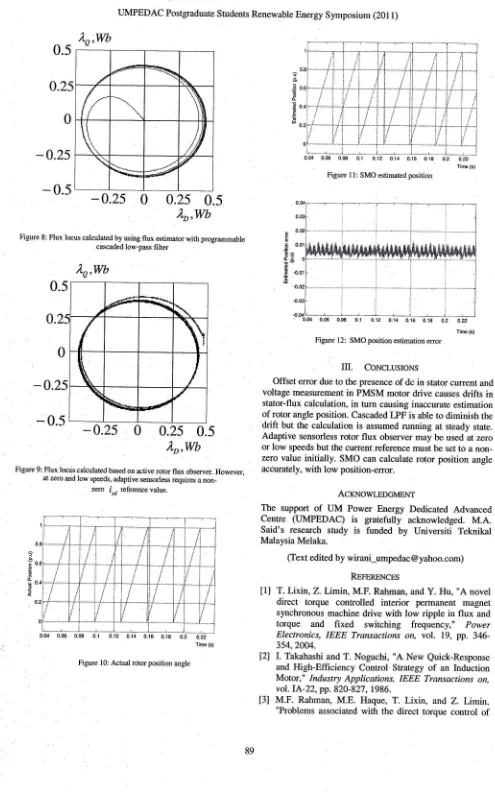
As Figure
9
shows, adaptive sensorless rotorflux
observer "unUJop"t","d
from zero speed. The switch from open-loop
""rt
"f
tL
start up to closed loop can befull of
noise and
give extreme speed transients. Adaptive sensorless operates
Lo*,".o
speed without changing the control structure'SMO simulation results show accurate speed and position
"rGuti*.
Figures10
and
1l
show
the
actualand
the
"rti*ut"a
anglis. The position angle erroras shown in Figure
l2
is under 0.015p.u, below 5 degrees of electrical angle' (43)"o'(4)=
+?
@)
The signal
flow
diagramfor
sliding mode observer can beimplemented as shown in Figure 5'
Figure 5: Block Dagram of SMO
TABLEIV.
DATA OF PMSMNumber of Pole
Pairs
P 8Armature
resistance
Rt.t
o
Magnet fluxlinkage
)' 0.28 Wbd-axis
inductance
La 8.65 mHo-axis
inductance
Lo 8.65 mHInertia
J
0.0051kg.m'Friction
factor
F
0.0050 N.m.sII.
RESULTSThe
observer behaviorswere
testedin
Matlab/Simulinkrofi**"
simulationtool.
Parametersof
thePMSM
modelare as tabulated in Table I.
-0.25
[image:4.540.283.502.129.622.2] [image:4.540.305.495.180.379.2] [image:4.540.291.506.378.616.2]0.25
LD'wb
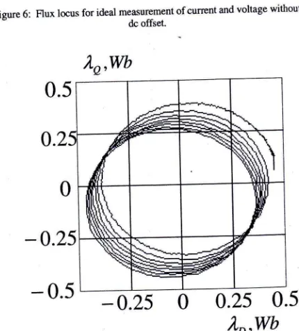
Figure 6: Flux locus for ideal measurement of cunent and voltage without dc offset.
-0.25
0.25
lD,w
Figure 7: Flux locus with stator cunent measurement considering & offset'
In
sensorless drive operation, the estimated statorflux
is used to calculate torque,flux,
and rotor position' DTC dt'iveimplementation
requires
all
three
observer outputs
asfeJJbacts
to
closed-loopcontrol.
Meanwhile,FOC
driveneed position
feedbackto
transform
the
stator
current measuiedfrom
stationaryreference
aB
frameto
rotating reference framef,q
.Figure
6
shows theflux
locus calculatedfrom
an idealinpuritator
currentwithout
the-p-resence
of
dc
offset'
Inaitual
implementation,with
an offset measurement present' there isu'd.ift io
stator flux locus, caused by the offset error in flux linkage estimation.Cascaded
LPF
will
compensatethe-offset.error;
seeFigure 8.
A filter
resets the integrator used in estimating the*tit*
nu*
fnkage. Theflux
locus is seen to remain centeredoo
th"
o.igin.It-clearly
startsfrom
the origin, requiring aninitial
rotoi
position. The observer also dependson
motorfrequency 6a, requiring the motor to run at some speed flrst before the cascaded LFF can be implemented'
)'o,wb
Cumrt Obcarus
Eq. (24,(28)
LPF
Back EMF
Obsfls
Eq. (36),(37),(38) (41),(42),(43),(44)
rslrn0.)- Z5
)'o,wb
--t!-
R\
Ur
/r'
t/
\
\\
/#
\
-*=
--#
{
UMPEDAC Postgraduate Students Renewable Energy Symposium (2011)
0.5
0.25
0
-0.25
-
0.5
Figure 8: Flux locus calculated by using flux astimator with programrnable cascaded low-pass fi lter
)"a,wb
-0.2
-0.2s
0
0.25
0.5
)'D,Wb
Figure 9: Flux locus calculated based on active rotor flux observer. However, at zero and low speeds, adaptive sensorless requires a
non-,oo
i"a
reference value.
[image:5.573.18.513.43.836.2]0.04 0.06 0.08 0.1 0.J2 0..t4 0.16 0.18 0.2 0.22 Tme (s) Figure l0: Actual rotor position angle
0.u 0.06 0.08 0.1 0.12 0.14 0.16 0.18 0.2 cn
Tire (s)
Figure 1 1: SMO estimated position
Figure 12: SMO position estimation error
M.
CoNCTSIoNsOffset error due to the presence of dc in stator current and voltage measurement
in
PMSM motor drive causes driftsin
stator-flux calculation, in turn causing inaccurate estimation of rotor angle position. Cascaded l,PF is able to diminish the
drift
but the calculationis
assumed running at steady state. Adaptive sensorless rotorflux
observer may be used at zero or low speeds but the current reference must be set to a non-zero valueinitially.
SMO can calculate rotor position angle accurately, with low position-error.ACKNoWLEDGMEI.IT
The
supportof
UM
Power Energy Dedicated AdvancedCentre (UMPEDAC)
is
grarefully
acknowledged. M.A.Said's
researchstudy
is
funded
by
Universiti
TeknikalMalaysia Melaka.
(Text edited by [email protected]) RepgneNcEs
[1]
T.Lixin,
Z.Limh,
M.F. Rahman, andY.
Hu,"A
noveldirect
torque controlled
interior
permanent magnet synchronous machine drivewith
low ripplein
flux
andtorque
and fixed
switching frequency,"
PowerElectronics,
IEEE
Transactionson,
vol.
19,pp.
346-354,2004.
[2]
I.
Takahashi and T. Noguchi,"A
New Quick-Responseand High-Efficiency Control Strategy
of
an InductionMotor,"
Indu:stry Applications,IEEE
Transoctions on, vol. IA-22, pp. 820-827, 1986.t3l
M.F.
Rahman,M.E.
Haque,T. Lixin,
arrdZ.
Limm,
"Problems associated
with
the direct torque controlof
-0.25
0
0.2s
0.5
)'D,Wb
A
LJMPEDAC Postgraduate Students Renewable Energy Symposium
(201l)
an interior permanent-magnet synchronous motor driveand
their
remedies,"
Industrial
Electronics,
IEEETransactions on, vol.51, pp. 799-809,20M.
[4]
H. Rasmussen, P. Vadstrup, and H. Borsting, "Adaptive sensorless field oriented control of PM motors includingzero
speed,"in
Industrial Electonics,
204
IEEE Intemational Symposium on,2004,pp.
1191-1196 vol. 2.[5]
L.
Changshengand
M.
Elbululq
"A
sliding
mode observerfor
sensorlesscontrol
of
permanent magnetsynchronous
motors,"
in
Industry
Applications Conference,2(W.
Thirty-Sixth
IASAnnual
Meeting. Conference Record of the 2001IEEE,20Ol,
pp. 1273-1278 vol.2.t6l
J.
l,ee,
J.
Son, andH. Kim, "A High
Speed Sliding Mode Observerfor
the Sensorless Speed Confiolof
aPMSM," In"dustrial Electronics, IEEE Transactions on,
vol.PP,pp.l-1.
[7]
G.
Foo and
M.F.
Rahman,"Direct
torqueand flux
controlled
IPM
synchronous motor drive using a hybridsignal injection and adaptive sliding mode observer," in
.
TENCON 2009-
2009IEEE
Region10
Conference, 2009, pp.l-7.
[8]
J. Dong,Z.
Zltengnng,
andW.
Fei,"A
Sliding Mode