IMPROVED PERFORMANCE DC MOTOR CONTROL USING A UNIPOLAR SWITCHING SCHEME
Liza bt Ahamat Mahmod Bachelor of Electrical Engineering
“ I hereby declare that I have read through this report entitle “Improved Performance of DC Motor Control Using a Unipolar Switching Scheme” and found that it has comply the partial fulfillment for awarding the degree of Bachelor of Electrical Engineering (Power Electronic and Drive)”
Signature : ………..
IMPROVED PERFORMANCE OF DC MOTOR CONTROL USING A UNIPOLAR
SWITCHING SCHEME
LIZA BT AHAMAT MAHMOD
This report is submitted in partial fulfillment of requirements for the degree of
Bachelor in electrical engineering (Power Electronics and Drive)
Faculty of Electrical Engineering
UNIVERSITI TEKNIKAL MALAYSIA MELAKA
I declare that this report entitle “Improved Performance of DC Motor Control Using a Unipolar Switching Scheme” is the result of my own research except
as cited in the references. The report has not been accepted for any degree and is not concurrently submitted in candidature of any other degree.
Signature : ………
Name : LIZA BT AHAMAT MAHMOD. Date : 25 June 2012
ii
ACKNOWLEDGEMENT
ALHAMDULILLAH, I am grateful to God for His blessing and mercy of the His to make this project successful and complete in this semester. First of all, I would like to express to Universiti Teknikal Malaysia Melaka. The special thanks goes to my helpful supervisor Dr.Auzani bin Jidin for giving invaluable guidance supervision, committed and sustained with patience during this project. The supervision and support that he gave truly help the progression and smoothness in the Final Year Project. In addition, I also wish to express to all the people involved in this thesis either directly or not, especially to the entire lecture who have taught me. Thank you for the lessons that have been taught.
My sincere thanks go to all my friends is the one same guidance under Dr.Auzani bin Jidin, who are Nor Hasina, Mohd Zharif Rifqi, Muhd Hafizuddin, Ahmad Shah Erwan and Mohd Hafizi because willing to support and gives some knowledge to achieve the aim for this final year project. Instead of that, special thanks thank I gave to another supporter friends who sincerely give their opinion and continuous guidance throughout this FYP.
Not forgotten also, thanks to my family for their support and endless encouragement to successfully complete in this project.
iii
ABSTRACT
This report presents the improvement performance of DC motor drive in terms of torque ripple, dynamic control and switching frequency. These motor drive is very essential for industrial applications. To improve performance of motor drive, precise control for some variable such as current (or torque), speed and position are necessary. The overall system is simulated using Matlab where the different switching techniques operation, output current and voltage are presented. The performance of three control switching technique which are bipolar-hysteresis, bipolar-triangular and unipolar-triangular are analyzed and discussed. Each switching technique for controlling the armature current (or torque) of DC machine was implemented using ezdsp F28335, with sampling period at 50us. The improvements of unipolar switching technique (i.e. minimization of torque ripple and provide constant switching frequency) compared the other switching techniques can be verified through simulation and experimentation.
iv
ABSTRAK
Laporan ini membentangkan peningkatan prestasi pemacu motor AT dari segi riak tork, kawalan dinamik dan frekuensi pensuisan. Motor pemacu ini sangat penting untuk diaplikasikan dalam industri. Untuk meningkatkan prestasi pemacu motor kawalan tepat untuk beberapa pembolehubah seperti arus (atau tork), kelajuan dan kedudukan adalah perlu. Keseluruhan sistem disimulasikan menggunakan Matlab di mana teknik pensuisan yang berbeza, output arus dan voltan telah dibentangkan. Prestasi tiga kaedah pensuisan iaitu dwikutub-arus histerisis, dwikutub-segitiga dan ekakutub-segitiga juga telah dianalisis dan dibincangkan. Setiap teknik pensuisan untuk mengawal arus angker (atau tork) mesin DC telah dilaksanakan dengan menggunakan ezdsp F28335, dengan tempoh persempelan 50us. Peningkatan teknik pensuisan unipolar (meminimumkan riak tork dan menyediakan frekuensi pensuisan malar) berbanding teknik pensuisan yang lain boleh ditunjukkan melalui simulasi dan eksperimen.
v 2.2 Four-Quadrant Operation in Variable
vi
3.1 Methodology of the project 22
3.2 Project Flow Chart 23
3.3 Software Development 25
3.4 Hardware Implementation 27
3.5 Project Phase 30
4 DESCRIPTION OF THE EXPERIMENTAL 31
SET-UP
4.1 Introduction 31
4.2 ezdsp F28335 Digital Signal Processor (DSP)-Board 32 4.3 Complex Programmable Logic Devised (CPLD) 33
4.4 Gate Drivers 34
vii 5.4 Comparison between Unipolar-triangular,
Bipolar-triangular and bipolar-hysteresis
in term switching frequency and torque ripple 46
viii
LIST OF TABLES
TABLE TITLE PAGE
5.1 Parameter System of DC Motor 36 5.2 Table comparison switching scheme 51
ix 2.4 Speed control of a DC motor with inner torque loop
control using full bridge DC-DC converter 10
2.5 Speed-Torque Characteristic 11
2.6 The result 4-quadrant speed control of DC motor 12
2.7 Bipolar switching circuit 13
2.8 Bipolar switching circuit for Leg A and Leg B 14 2.9 Control signal and triangular waveform of bipolar
switching scheme 14
2.10 Transfer function of the bipolar switching scheme 15
2.11 Unipolar switching circuit 16
x
FIGURE TITLE PAGE
2.12 Control signal and triangular waveform of unipolar
switching scheme 16
2.13 Transfer function of the unipolar switching scheme 17 2.14 Voltage current relation of an inductor for unipolar scheme 18 2.15 Voltage current relation of an inductor 18 2.16 Voltage-current relation of an inductor for bipolar scheme 20
3.1 Project Flow Chart 24
3.2 Simulation Flow Chart 25
3.3 Simulation block diagram using simulink library 26
3.4 Overall hardware implementation 27
4.1 Complete drive system 31
4.2 ezdsp F28335 Digital Signal Processor (DSP)-Board 32
xi
FIGURE TITLE PAGE
5.6 Full-bridge DC-DC Converter 41 5.7 Look under Subsystem of bipolar-hysteresis 42 5.8 Waveform of bipolar-hysteresis 42 5.9 Look under Subsystem of bipolar-triangular Switching 43 5.10 Waveform of bipolar-triangular Switching 43 5.11 Look under Subsystem of Unipolar-triangular Switching 44 5.12 Waveform of Unipolar-triangular Switching 44 5.13 The motor output voltage and current in forward direction 45 5.14 The motor output voltage and current in reverse direction 45 5.15 Bipolar hysteresis :(a) simulation, (b) experimental 47 5.16 Bipolar-triangular :(a) simulation, (b) experimental 48 5.17 Bipolar-triangular :(a) simulation, (b) experimental 49 5.18 experimentation result : (a) bipolar-hysteresis,
(b) bipolar-triangular, (c) unipolar-triangular 50
xii
LIST OF ABBREVIATION
PWM - Pulse Width Modulation
DC - Direct Current
ezdsp - Digital Signal Processor from Texas Instrument IGBT - Insulated Gate Bipolar Transistor
CPLD - Complex Programmable Logic Devised
MOSFET - Metal-oxide Semiconductor Field Effect Transistor DSP - Digital Signal Processor
xiii
- Mechanical power - Micro Second
Ω - Unit for resistance (OHM)
- Unit for inductance (Henry)
xiv
LIST OF APPENDICES
APPENDICES TITLE PAGE
A eZdsp Quick Start Installation Guide 56 B Digital Signal Processor (eZdsp) Feature 59
CHAPTER 1
INTRODUCTION
1.1 Introduction
2
1.1.1 Background of DC Motor
Direct current (DC) motors have various characteristics and are used extensively in variable-speed drives. Many industrial applications use DC Motor because the speed and torque relationship can be varied. DC Motor provides excellent control of speed for acceleration and deceleration [1]. The power supply of a DC Motor connect directly to the field of the motor which allows for precise voltage control, and is necessary for speed and torque control applications. However the performances of DC motor control systems are reduced by the effect of DC motor variable torque but the control system of a DC motor will increase the electric current in a DC motor to maintain a desirable speed when the DC motor receives the variable torque or disturbance torque[2].
DC motor is one machines devised to convert electrical power into mechanical power. Permanent magnet (PM) direct current converts electrical energy into mechanical power. It is becoming more popular in many control systems because of high power density, large torque to inertia ratio, small and high efficiency [3]. It is probably the most commonly used DC Motors, but there are also use coils to make permanent magnetic field, movement of magnetic field is achieved by switching current between coils within the motor which is called commutation. PM motors are usually physically smaller in overall size and lighter for a given power rating [1]. Furthermore, since the motor's field, created by the permanent magnet, is constant, the relationship between torque and speed is very linear. A Permanent Magnet motor can provide relatively high torque at low speeds and permanent magnet field provides some inherent self-braking when power to the motor is shutoff[4].
3
conjunction with the highly demand for the drives in so many field of works and needs especially in engineering sector, factory automation and our daily life, the motor accuracy and effectiveness have to be improved [1].
1.1.2 Proportional Integral (PI) Controller
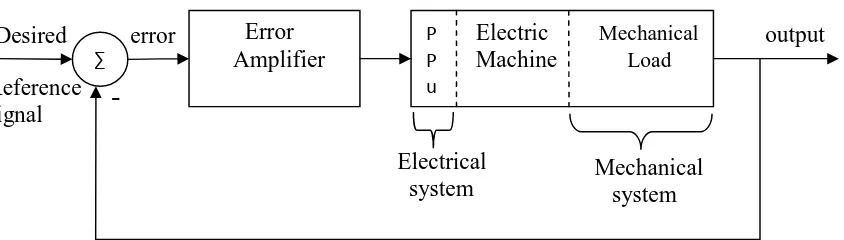
PI Controller (proportional integral controller) is a feedback controller which drives the plant to be controlled with a weighted sum of the error (difference between the output and desired set point) and the integral of that value[10]. Motion control system often utilizes a proportional integral (PI) controller. Which is the P controller in the position loop and PI Controller in the speed and torque loop are often adequate. PI controller consist Kp and Ki where Kp is proportional-controller gain and Ki is the integral-controller gain [8]. It implemented in this transfer function to obtain zero steady-state error and good dynamic responses such as fast transient responses with minimum overshoot and make the system less sensitive to disturbances and changes in the system parameters.
1.1.3 Cascade Control Structure
4
1.1.4 Switch-Mode Converters in Electric drives
The power electronic converters are used to obtain an adjustable DC voltage applied to the armature of a DC motor. There are basically two types of converter normally employed in DC drive which is controlled rectifier and switch mode converter. To develop the model of power electronic converters will depend on the application of the model. The model for a switching device used to analyze or switching losses is different from a model develop used to study the fundamental behaviour of a converter containing that particular switching device [11].
1.2 PROJECT OBJECTIVE
The objectives of this project are:
1. To improved DC motor drive performance in terms of torque ripple, dynamic control and switching frequency by using unipolar switching scheme.
2. To developed the DC motor drive using ezdsp F28335.
1.3 SCOPE
5
Overcurrent condition during starts-up when application of large DC voltage to the DC motor that contains resistive and inductive load.
Torque as well as current cannot be controlled and predictable when variation of load torque is subjected to the DC motor control system.
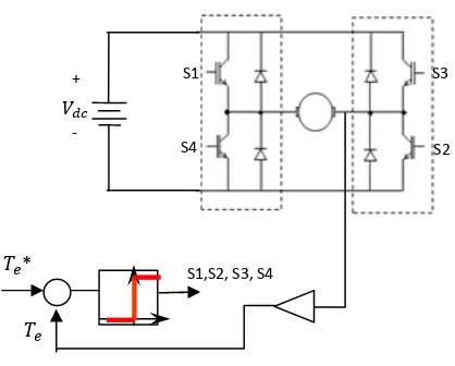
To solve the problem, a torque control loop with bipolar-hysteresis control for full bridge DC-DC converter of DC motor drive can be used as shown in figure 1.2. However, the another problem raises namely larger torque ripple and variable switching frequency due to the bipolar switching scheme and hysteresis employed in the DC drive system.
6
CHAPTER 2
LITERATURE REVIEW
2.1 Mathematical Modelling of DC Motor
7
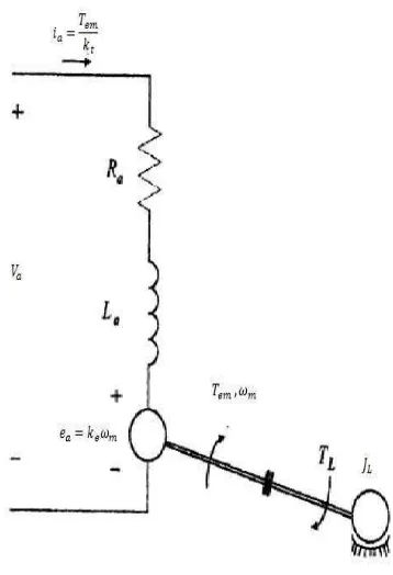
In a DC motor, permanent magnets on the stator produce a constant field flux ∅ as shown in Figure 2.2. The electromagnet torque T is produced by the interaction of the field flux, ∅ and the armature current, . The current and the torque are proportional to each other.
The mechanical equation:
= ∅ (2.2)
where is the torque constant of the motor.
In the armature circuit, a back emf is produced by the rotation of armature conductors at a speed in the presence of a field flux ∅
The electrical equation:
= ∅ (2.3)
where is a voltage constant of the motor.