ISSN: 1693-6930
accredited by DGHE (DIKTI), Decree No: 51/Dikti/Kep/2010 539
A Simplified Voltage Vector Selection Strategy for
Direct Torque Control
Li Yaohua*, Liu Jingyu, Ma Jian, Yu Qiang
“Traffic New Energy Development, Application and Energy Saving of Automobile” Key Laboratory of Shaan’xi Province of School of Automobile of Chang’an University
Nan Er Huan Zhong Duan, 710064, Xi’an City, China, Ph. /Fax: +0086-2982334987/82334986 e-mail: [email protected]
Abstrak
Kendali torsi langsung (DTC) untuk motor sinkron magnet permanen (PMSM) dengan kendali tabel penyaklaran memiliki kekurangan pada riak torsi yang tinggi dan frekuensi penyaklaran yang variabel. Untuk sistem DTC PMSM, strategi pemilihan vektor tegangan sebagai prinsip kendali histeresis menentukan kinerja sistem. Sudut (α) antara vektor fluks stator dan vektor tegangan yang dipilih, menentukan efek vektor tegangan pada amplitudo fluks stator dan sudut torsi. Efek dari vektor tegangan pada toque tergantung pada α, sudut torsi dan parameter PMSM. Sebuah strategi pemilihan vektor tegangan berdasarkan teknologi modulasi vektor ruang (SVM) diusulkan untuk mengendalikan fluks stator, sudut torsi dan torsi. Hasil eksperimen yang diujikan pada motor PMSM 15-kW jenis interior menunjukkan bahwa riak arus dan torsi stator dapat diturunkan dengan frekuensi switching yang konstan.
Kata kunci: DTC, PMSM, SVM, strategi pemilihan vektor tegangan
Abstract
The direct torque control (DTC) for permanent magnet synchronous motor (PMSM) under the control of switching table suffers from high torque ripple and variable switching frequency. For PMSM DTC system, voltage vector selection strategy as the hysteresis control principle determines the system’s performance. The angle (α) between stator flux vector and the applying voltage vector determines effect of the voltage vector on the amplitude of stator flux and torque angle. The effect of the voltage vector on toque is dependent on α, torque angle and parameters of PMSM. A voltage vector selection strategy based on the technology of space vector modulation (SVM) is proposed to control stator flux, torque angle and torque. Experimental results for a 15-kW interior PMSM show it can decrease stator current and torque ripples and fix the switching frequency.
Keywords: DTC, PMSM, SVM, voltage vector selection strategy
1. Introduction
The direct torque control (DTC) for permanent magnet synchronous motor (PMSM) possesses have many advantages: simple control configuration, low parameter dependency, fast dynamic response, lack of coordinate transformation and rotor position except for the initial position. But it also suffers from some disadvantages, especially high torque ripple and variable switching frequency [1]-[3]. In nature the DTC is the hysteresis control. Voltage vector selection strategy as the hysteresis control principle determines the system’s performance. Normally switching table is used as voltage vector selection strategy to control the amplitude of stator flux and torque. But switching table can’t always satisfy the control of torque [4], [5]. Thus to study voltage vector selection strategy is critical to improve the PMSM DTC system’s performance [6]-[8].
2. Effects of Voltage Vector
Neglecting voltage drop on stator resistance, after applying voltage vector
V
sr
for a short
period ∆t, stator flux vector of the motor is presented in (1) and Figure 1. Figure 1 implies the application of voltage vector will change the amplitude and angular position of stator flux vector at the same time. And the latter will affect the change of torque angle, the angle between stator
and rotor flux vectors. The initial stator flux vector is
ψ
r
s. After applying
V
sr
for ∆t, it is
ψ
r
s′
.
t
V
t
R
i
t
V
s s s s ss
s
=
+
⋅
∆
−
⋅
⋅
∆
≈
+
⋅
∆
′
r
r
r
r
r
r
ψ
ψ
ψ
(1)s
ψ
r
sδ
∆
s
ψ
r
′
t
V
s⋅
∆
r
α
Figure 1. The move of stator flux vector
According the law of cosine and Figure 1, after applying voltage vector
V
sr
for ∆t, the amplitude of stator flux can be expressed in (2).
α
ψ
ψ
ψ
s′
=
s2+
(
V
s⋅
∆
t
)
2+
2
s⋅
V
s⋅
∆
t
⋅
cos
)
)
)
)
)
(2)Here we define q shown in (3). Thus (2) can be rewritten into (4).
s
s
t
V
q
=
)
⋅
∆
/
ψ
)
(3)α
ψ
ψ
)
s′
=
)
s1
+
q
2+
2
q
cos
(4)As
ψ
s>
0
)
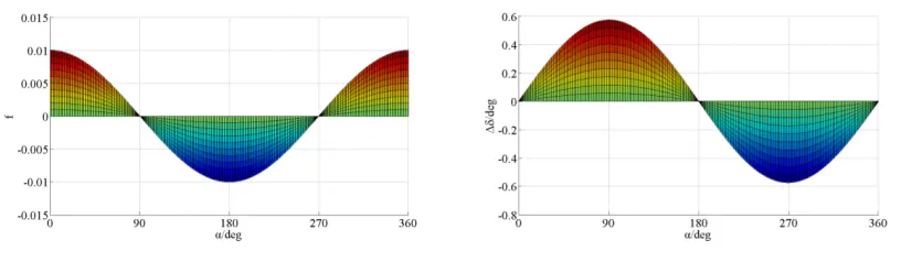
holds true, we define f shown in (5) to represent the change of the
amplitude of stator flux due to the application of the voltage vector. If f>0 means the voltage vector increases the amplitude of stator flux and if f<0 means the voltage vector decreases it.
1
cos
2
1
+
2+
−
=
q
q
α
f
(5)According the law of sine and equ. (3), neglecting the move of rotor flux vector, after applying the voltage vector for ∆t, the change of torque angle can be expressed in (6).
α α δ
δ
cos 2 1
sin arcsin
2
q q
q
s
+ + =
∆ ≈
∆ (6)
Figure 2. f versus α Figure 3. ∆δ versus α
In stator flux reference frame, the torque of PMSM in terms of the amplitude of stator flux and torque angle is presented in (7).
] 2 sin ) ( sin 2 [ 4 3 δ ψ δ ψ ψ d q s q f q d s
e L L L
L L
p
T = − ) −
)
(7)
Here we define k as the following and (7) can be rewritten into (9).
f q s d q L L L k ψ ψ) ) ( − = (8) ) cos sin (sin 2 3 δ δ δ ψ ψ k L p T d s f
e= −
)
(9)
According to the definition of k and equation. (4), after applying voltage vector for ∆t, the value of k is presented in (10).
α
cos 2
1 q2 q
k
k′= + + (10)
Substituting (4), (6) and (10) into (9), after applying voltage vector for ∆t, the torque of PMSM is shown in (11).
)] cos 2 1 sin arcsin cos( ) cos 2 1 sin arcsin sin( ) cos 2 1 ( ) cos 2 1 sin arcsin sin( cos 2 1 [ 2 3 2 2 2 2 2 α α δ α α δ α α α δ α ψ ψ q q q q q q q q k q q q q q L p T d s f e + + + + + + + + − + + + + + = ′ ) (11)
As
0
2
3
>
d s fL
p
ψ
ψ
)
holds true, we define M shown in (12) to represent the change of torque
due to the application of voltage vector. If M>0 means voltage vector increases torque and if M<0 means voltage vector decreases torque.
] cos sin ) cos 2 1 sin arcsin cos( ) cos 2 1 sin arcsin sin( ) cos 2 1 [( sin ) cos 2 1 sin arcsin sin( cos 2 1 2 2 2 2 2 δ δ α α δ α α δ α δ α α δ α − + + + + + + + + − − + + + + + = q q q q q q q q k q q q q q M (12)
The tested motor is a 15kw interior PMSM. Its parameters are shown in Table. 1. The reference amplitude of stator flux is 0.06Wb. According to equ. (8) and Table. 1, k=0.238. According to (12), M versus α with 0°<δ<90° and k=0.238 is shown in Figure 4. Figure 4 shows if the angle between stator flux vector and the applying voltage vector is within (0°, 103°), voltage vector increases torque and if the angle is within (180°, 282°), voltage vector decreases torque.
Table 1. The Parameters of tested PMSM Parameters Notations values
Pole pairs p 6
Stator resistance Rs 0.0142Ω
d-axis stator inductance
Ld 0.6660mH
q-axis stator inductance
Lq 0.8745mH
Permanent flux ψf 0.06Wb
Figure 4. M versus α
3. Voltage vector selecton strategy
According to effects of voltage vector on the amplitude of stator flux, torque angle and torque of the tested PMSM, the selection area for V11 (voltage vector to increase the amplitude of stator flux, torque angle and torque) is (δs, δs+90°),the selection area for V01 (voltage vector
to decrease the amplitude of stator flux and increase torque angle and torque) is (δs+90°,
δs+103°),the selection area for V00 (voltage vector to decrease the amplitude of stator flux,
torque angle and torque) is (δs+180°, δs+270°),the selection area for V10 (voltage vector to
increase the amplitude of stator flux and decrease torque angle and torque) is (δs+270°, δs+283°), where δs is the angular position of stator flux vector in the stationary reference frame.
According to voltage vector selection area, a simplified voltage vector selection strategy for the tested motor is proposed shown in (13).
+
∠
=
∠
+
∠
=
∠
+
=
∠
+
=
∠
° °
° °
° °
° °
)
360
,
180
mod(
)
360
,
180
mod(
)
360
,
100
mod(
)
360
,
60
mod(
01 10
11 00
01 11
V
V
V
V
V
V
s s
r
r
r
r
r
r
δ
δ
(13)
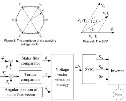
The angular position of voltage vector obtained by equ. (13) is arbitrary, so the technology of space vector modulation (SVM) must be used to generate the applying voltage vector. In the SVM, the amplitude of the applying voltage vector is constant which is the radius of the inscribed circle of the hexagon shown in Figure 5. According to Figure 5, it is shown in (14), where Udc is the dc-link voltage.
dc
s
U
V
3
3
=
)
We assume that the applying voltage vector locates between V1 and V2 shown in Figure 6, where γ is the angle between V1 and the applying voltage vector Vs.
According to the law of sine, (15) holds true.
°
°
−
=
=
120
sin
3
3
)
60
sin(
3
2
sin
3
2
U
dcT
2U
dcT
1U
dcT
sγ
γ
(15)Thus the applying time of V1, V2 and V0 in a sampling period is shown in (16).
−
−
=
⋅
=
⋅
−
=
°2 1 0
2 1
sin
)
60
sin(
T
T
T
T
T
T
T
T
s s
s
γ
γ
(16)
The diagram of the PMSM DTC system using voltage vector selection strategy is shown in Figure 7.
1 V
r
2 V
r
3 V
r
4 V
r
5 V
r
6 V
r
s
V r
Figure 5. The amplitude of the applying voltage vector
1
V
r
s sV T
r
2V
r
1 1
V T
⋅
r
2 2V T
⋅
r
120
°γ
Figure 6. The SVM
Motor
S
AStator flux
comparator
+−+
Inverter
Angular position of
stator flux vector
SVM
sV
∠
r
Voltage
vector
selection
strategy
S
BS
Cs
δ
Torque
comparator
φ
τ
e
T
*e
T
s
ψ
)
*s
ψ
)
−
Figure 7. The PMSM DTC system using voltage vector selection strategy
4. Experimental results 4.1. Test bench
modules (Semikron semix 202GB066HDs) are used for the inverter. With the help of Real Time Interface (RTI) software, real-time control codes are generated automatically from the Simulink model. The test bench is shown in Figure 8, where a DC machine is used to load the PMSM and a torque meter is used to measure the load torque.
Figure 8. Test bench
4.2. Switching table
Switching table is used as voltage vector selection strategy of the PMSM DTC system shown in Table. 2. The reference amplitude of stator flux is 0.06Wb. The reference speed is 100rpm. The hysteresis band for the amplitude of stator flux is 0.002Wb and the hysteresis band for torque is 0.002Nm. The sampling period for speed control loop is 0.01s and the sampling period for stator flux and torque control loop is 350μs.
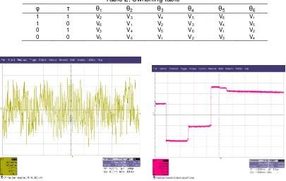
Table 2. Switching table
φ τ θ1 θ2 θ3 θ4 θ5 θ6
1 1 V2 V3 V4 V5 V6 V1
1 0 V6 V1 V2 V3 V4 V5
0 1 V3 V4 V5 V6 V1 V2
0 0 V5 V6 V1 V2 V3 V4
When the motor speed is 100rpm at empty-load, the phase stator current and the a-phase stator voltage of the PMSM are shown in Figure 9 and Figure 10. When the motor speed is 100rpm, a negative load torque is applied on the PMSM. And the a-phase stator current (the yellow wave) and the load torque (the red wave) are shown in Figure 11.
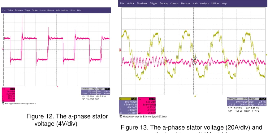
Figure 10. The a-phase stator voltage (20A/div) and the load torque (10Nm/div)
Figure 11. The a-phase stator current (5A/div)
4.3. Voltage vector selection
Voltage vector selection strategy shown in (13) is used in the PMSM DTC system. The reference amplitude of stator flux is 0.06Wb. The reference speed is 100rpm. The hysteresis band for the amplitude of stator flux is 0.002Wb and the hysteresis band for torque is 0.002Nm. The sampling period for speed control loop is 0.01s and the sampling period for stator flux and torque control loop is 350μs.
When the motor speed is 100rpm at empty-load, the phase stator current and the a-phase stator voltage of the PMSM are shown in Figure 11 and Figure 12. When the motor speed is 100rpm, the same negative load torque is applied on the PMSM. And the a-phase stator current (the yellow wave) and the load torque (the red wave) are shown in Figure 13.
Figure 12. The a-phase stator voltage (4V/div)
4.4. Analysis
According to Figure 8 and Figure 11, voltage vector selection strategy can decrease stator current ripple compared with switching table. According to Figure 9 and Figure 12, voltage vector selection strategy can fix the switching frequency compared with switching table. According to Figure 10 and Figure 13, voltage vector selection strategy can decrease stator current and torque ripples compared with switching table.
5. Conclusion
In this paper, effects of voltage vector on the amplitude of stator flux, torque angle and torque of the PMSM DTC system is studied. If the angle between stator flux vector and the applying voltage vector is within (-90°, 90°), voltage vector increases the amplitude of stator flux and if the angle is within (90°, 270°), voltage vector decreases the amplitude of stator flux. If the angle is within (0°, 180°), voltage vector increases torque angle and if the angle is within (180°, 360°), voltage vector decreases torque angle. The change of torque due to the application of voltage vector is dependent on k, δ and α. A simplified voltage vector selection strategy for the tested PMSM is proposed, where the SVM is used to generate the applying voltage vector. Eperimental results show voltage vector selection strategy can decrease stator current and torque ripples and fix the switching frequency compared with switching table.
Acknowledgements
This work was financially supported by China Postdoctoral Science Foundation funded project (20110491636) and Special Fund for Basic Scientific Research of Central Colleagues, Chang’an University funded project (CHD2011JC136).
References
[1] Zhong L, Rahman MF, Hu WY, Lim KW. Analysis of direct torque control in permanent magnet synchronous motor drives. IEEE Transactions on Power Electronics. 1997; 12(3): 528-536.
[2] Zhong L, Rahman MF, Hu WY, Lim KW. A direct torque controller for permanent magnet synchronous motor drives. IEEE Transactions on Energy Conversion. 1999; 14(3): 637-642.
[3] Rahman MF, Zhong L, Lim LW. A direct torque-controlled interior permanent magnet synchronous motor drives incorporating field weakening. IEEE Transactions on Industry Application. 1998; 34(6): 1246-1253.
[4] Yaohua Li, Weiguo Liu. Simulation Study on the Effect of Voltage Vector on Torque in Direct Torque Control System of Permanent Magnet Synchronous Motor. The Second IEEE Conference on Industrial Electronics and Applications (ICIEA). Harbin. 2007: 1521-1525.
[5] Yaohua Li, Dieter Gerling, Weiguo Liu. A Novel Switching Table to Suppress Unreasonable Torque Ripple for the PMSM DTC Drives. International Conference on Electrical Machines and Systems (ICEMS). 2008: 972-977.
[6] Yaohua Li, Dieter Gerling, Weiguo Liu. The Control of Stator Flux and Torque in the Surface Permanent Magnet Synchronous Motor Direct Torque Control System. The 4th IEEE Conference on Industrial Electronics and Applications (ICIEA). Xi’an. 2009: 2004-2009.
[7] Li YH, Gerling D, Liu WG. A Simplified Voltage Vector Selection Strategy for the Permanent Magnet Synchronous Motor Direct Torque Control Drive with Low Torque Ripple and Fixed Switching Frequency. The 13rd International Conference on Electrical Machines and Systems. Brasov. 2010: 674-679.