DEVELOPMENT OF COMBINED VECTOR AND DIRECT TORQUE
CONTROL METHODS FOR INDEPENDENT TWO INDUCTION MOTOR
DRIVES
MD HAIRUL NIZAM BIN TALIB
PROFESOR MADYA DR ZULKIFILIE BIN IBRAHIM
N.A RAHIM
N.M YAAKOP
:Development of Combined Vector and Direct Torque
Control Methods for Independent Two Induction
Motor Drives
M.H.N. Talib1, Z.Ibrahim2, N.A. Rahim3, N.M.Yaakop4 1
•2 Faculty of Electrical Engineering, Universiti Teknikal Malaysia Melaka 3Faculty of Engineering, Universiti Malaya,
4Faculty of Engineering, University Kuala Lumpur Malaysian Spanish Institute, 1
•2 Melaka, Malaysia. 3
•4 Kuala Lumpur, Malaysia.
Email: [email protected], [email protected], [email protected], [email protected]
Abstract-Many applications use two or more motors operating
in parallel configuration by using one variable speed drive. This system is able to control these multiple motors at the same desired motor speed operation which provide advantages in terms of components and cost reduction. However, the system is not able to control each motor separately if it is desired to operate at different speeds and it also cannot withstand the load disturbance. To address this problem, the design of combined Vector Control-Direct Torque Control (DTC) methods is proposed and their performance is investigated for the case of independent controlled two induction motors fed by single Five Leg Inverter (FLI) method. Double Zero Sequence (DZS) Injection Method Space Vector Pulse Width Modulation (SVPWM) scheme is used for the FLI. Simulation results from the Simulink/Matlab that verify the validity of the method are also included. The results show the ability of the proposed method to control motor speed independently under forward-1·everse step speed command and load disturbance condition.
Keywords -Two Induction Motor Drive; Five Leg Inverter; Double Zero Sequence (DZS) Injection Method; Field Oriented Control (FOC); Direct Torque Control (DTC)
I. INTRODUCTION
Vector Control and Direct Torque Controls are becoming a choice for high perfonnance induction motor drive system in industrial applications. Most of the research and studies focused on the vector control or direct torque control with a single three-phase motor and a single-three leg inverter drive system [1, 2]. There are many industrial manufacturing processes that require high performance control of a multi motor operation under different loads and speeds requirement. The multi motor operations under this condition encourage research on the multi motor drive system by using a single inverter. The research offers advantage of allowing independent control of the motors with cost reduction and space minimization. The independent control of two inductions can be realized by using Four Leg Inverter[3, 4], Five Leg Inverter (FLI)[5-9]or Nine Switched Inverter[lO, 11]. This drive system offers cost reduction by reducing the numbers of power electronics switches devices, using only one DC bus supply, one DSP and less space. Many researches on the two motor control operation have discussed on the development of the inverter, motors connection, PWM strategy and performance analysis of the inverter. All of the system used vector control method for both motors. This paper focused on
the development of combined vector control and DTC methods with a single FLI system to operate two three phase induction motors independently.
One of the important components in independent control of two AC motor drive systems is the inverter control. Either in Four Leg Inverter, Five Leg Inverter (FLI) or Nine Switched Inverter, the PWM methods are used to control the switching gates to produce an appropriate output voltage to the motor. In the FLI topology, there are numerous PWM techniques [5, 7] such as Dual Voltage Modulation (DVM), Modulation Bock Method (MBM), Inversion Table Method (IVM), Double Zero Sequence Method (DZS) and Two Ann Modulation (TAM). The DZS is one of the best methods which enables an arbitrary distribution of the DC link voltage between the two motors and maintain to operate in constant switching frequency mode. DZS offer less complexity and easy to implement using standard DSP. This method is able to solve the drawback of previous PWM such as restriction of 50% of the DC bus voltage for one motor, asymmetrical switching frequency, underutilizing of the switching state, sideband harmonics, high magnitude THD generation and their complexity issue.
The vector control or DTC offers better dynamic performance of induction motor drives[l2]. The vector control imitates the principle of separately excited DC motor. Independent control of both magnetic field and torque is achieved. The vector control concept implies that the current components supplied to the machine should be split into a flux component and a torque component. The flux component of the current is oriented in phase with the rotor flux vector, and the torque component is oriented in quadrature. This system applied the indirect field oriented control (IFOC) which only required correct alignment of rotating reference frame with rotor flux frame. The flux orientation can be achieved by imposing a slip frequency derived from rotor dynamic equation. Thus, its offers more easy implementation and cost saving compared to the direct field oriented control method (DFOC).
work with the vector control to feed signal into the modulation of the FLI. Many research have been conducted to improve the DTC- SVM schemes introduced such as closed loop flux control, closed loop torque control and closed loop for flux and torque control. DTC scheme with closed loop and flux control is selected for this analysis because it offers better flux and "torque components control.
This paper proposes a combined vector control and DTC methods for independent control of two induction motors fed by a single FLI. FOC vector control method is used to control motor 1 (Ml) and DTC space vector modulation method is applied to the motor 2 (M2). The output of the stationary voltage demand of both methods is synthesized through the DZS SVPWM method to generate the required voltage to the FLI. The output voltage from the FLI is supplied to the three-phase induction motor accordingly.
IL FIVE LEG INVERTER
A. Five Leg Inverter (FLI) Configuration
The typical connection of the five leg voltage source inverter for two three-phase induction motors is shown in Figure 1 Each of the leg consists of two switches with a total number of ten switches altogether. Inverter legs A and B are connected to Ml meanwhile D and E legs are connected to M2. In the FLI topology, one leg is used as the common leg. This common leg is shared to the both motors. In this case, leg C is chosen as the common leg. All the legs are connected to the three-phase supply termination of the motors denoted as al,bl,cl and a2,b2,c2 to represent Ml and M2 termination respectively.
j
2Figure l : Connection between five leg inverter and motors
B. Double Zero Sequence (DZS) Injection Method Configuration
This simulation focused on the space vector PWM techniques applied using the DZS methods [5, 6, 16]. These methods are the best solution to the FLI issues nowadays. Even though this method faced the natural 」ッョウエイ。セウ@ of the FLI which requires the total voltage of the machmes must not
exceed the DC bus voltage, it is able to utilize any portion of the DC bus voltage to be allocated to any of the two machines.
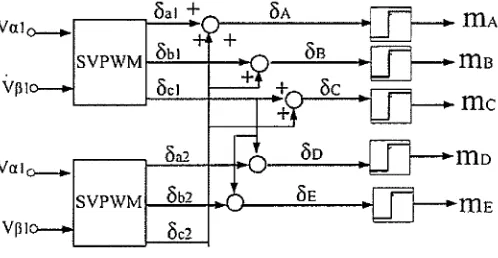
The space vector DZS block diagram is shown in Figure 2· This method utilizes the standard three-phase space vector modulator to generate modulation signals for the FLI.
oa1
+
OA
IDA
Vale--.
+
S VPWM
ゥM[oセ「ZNNZNNNNャ@
--t----1'"{ oc1v。ャセ@
oa2
svpwmャMMGo]「]RMヲMQQセMMMX⦅e@
⦅セ@
IDE
Vpl oc2
Figure 2 : Double Zero Sequence Injection Method block diagram.
Based on the principle, the first set of fundamental voltages in stationary frame is synthesized in the three-phase leg space vector modulator. This process is repeated for set 2. The output of the modulator is
o,
which can be considered as the duty cycle for each three leg. The output signals of set I and set 2 are than summed in an appropriate manner to reduce the number of modulation signals from six to five as presented in the block diagram configuration. The summed results of output set 1 and set 2 generate modulated signal for all the five legs of the inverter as equation below:OA = Oa1
+
OczOa = Ob1
+
OczOc
=
Oc1+
OczOv = Oa2
+
Dc1OE
=
Obz+
Oc1 (!)Finally, the modulation signals of the FLI which are noted as mA, m6 , me, m0 and mE respectively are compared to the
carrier signal to generate output voltage of the FLI. III. THREE-PHASE INDUCTION MOTOR MODEL
The MATLAB/Simulink model of three-phase induction motor is developed based on the following equations in synchronous reference frame[12].
Stator voltage equations:
- - dfPds _
vds = Rslds
+
dt-
Ws<fJqs- - dcpqs
-Vqs
=
Rslqs+
dt -
Ws(f)ds (2)Rotor Voltage equations:
_ - dcpdr (
[image:3.595.304.553.98.227.2] [image:3.595.26.281.371.555.2]- - dcpqr -Vqr.
=
0=
Rslqr+
dt
+
(Ws - Wr)cpdr Stator Flux equations:(j)ds
=
Lslds+
Lmldr(j)qs
=
Lslqs+
Lmlqr (4)Rotor Flux equations: cpdr = Lmlds
+
LrldrCi5qr = Lmlqs
+
Lrlqr (5)Torque equation
(6)
IV. FOC AND DTC CONFIGURATION IN FLI SYSTEM The block diagram of two induction motors applying FOC and DTC schemes in a FLI system is illustrated in Figure 3 The FOC scheme is applied to control motor Ml while the DTC scheme is applied to the motor M2. Both of the schemes are used to control the variable speed demand for forward and reverse direction. In a single three-phase motor with single inverter application, this method is proven to be able to control the motor torque and flux effectively in order to force the motor to accurately track the command regardless of the machine and load variation or disturbance.
,---1
I
I W<1·
I
I
I
I I
I abc to ap l•hcl
L---Figurc 3 : Two induction motor drive in FL! system diagramWith reference to Figure 3 the indirect FOC block diagram is applied to Ml. In this system, the rotating coordinate reference frame having direct axis is aligned with the rotor flux vector that rotate at the stator frequency. This results in a decoupling of the variable so that the flux and torque can be separately controlled by the direct axis stator current, id and the quadrature axis stator current, iq component. Based on the rotor voltage quadrature axis equation of induction motor, the rotor flux linkage can be estimated using this fonnula;
- Lmlds
l/Jr
= 1+
-CrS (7)where, Tr is the rotor time constant.
The slip frequency, w51 is obtained from the rotor voltage direct axis equation by:
(8)
The rotor flux position,
Be
for coordinate transform is generated from the integration of rotor speed, Wr and slip frequency,w
51 •. (Je
=
f
Wr+
Wsl(9)
The reference torque current, iq* is generated from the error of speed demand, rorl * and actual measure speed, rorl with the speed PI controller. Then the iq* is compared with the actual torque current component, iq and this gives the torque current error. This error is processed to generate the reference voltage torque component, Vq* . On the other hand, the reference flux component current, id* which has been set earlier to a constant value is compared with the actual values of this variable, id. The error signal is applied to PI controller to generate the command values of flux voltage components, Vd*. These reference voltages are then transformed into stationary reference frame voltage by dq to
Cif3
transformation for SVPWM modulation process.Meanwhile the DTC method block diagram is used to control the speed of M2. The value of stator voltage and stator current in stationary reference frame can be calculated by the equation below;
Vdc
l'sa
=
3(2sa - Sb - s,) VdcV5p
=
.J3
(sb - s,)1
l'sa
=
3
(2lsa - fsb - fsc)1
Vsp
=
.J?,Usb -fsc)(10)
The estimated value of the stator flux and electrical torque are derived from the motor equation in stationary reference frame given as:
( II)
The difference between speed reference, wr2* and speed feedback is amplified in the speed control amplifier of the PI controller and the output of the speed controller serves as the reference input to the torque component loop. The reference torque, Te* is compared with the estimated torque component,
Te
to produce torque error. This error is amplified through PI controller to generate the reference voltage torque component,Vsq*. The stator flux component, l'Vsl is set to a constant value and compared with the estimated value for stator flux
tfj
and is converted to direct axis voltage demand, Vd*. Then, both voltage components in rotating reference frame are transformed to the stationary reference frame by dq toCif3
transformation. The second set of reference voltage vector is "synthesized through the modulation of the FLT.V. SIMULATION RESULT OF SPEED CONTROL OPERATION
A. Parameter Set-up
Simulations have .been carried out for the two motor controls for the FLI by using SVPWM method. A dedicated speed range and torque load is applied to understand the performances of the FOC and DTC method with the FLI through the motors performances. Two similar types of three-phase induction motors are used in the simulation studies and details about the motor parameters are shown in Table I below.
TABLE I. INDUCTION MOTOR PARAi\1ETERS
Motor Specifications Value
Rated Voltage 380V
Rated Frequency 50 Hz
Poles 4
Rated Speed 1430 rpm
Stator Resistance 6.460
Rotor Resistance 3.617 n
Stator lnductance 0.34257 H
Rotor Inductance 0.32903 H
Magnetizing Inductance 0.3118 H
Inertia 0.008kgm2
Based on the two induction motor dnves fed by a single jnverter principle, the summed voltage requirement of both motors must be within the DC bus voltage supply. The FLI is supplied by using 537V DC supply and carrier frequency is set at 3kHz. Thus, this simulation is performed with a few speed ranges for forward and reverse operation by abiding to this principle in order to understand the speed behaviors. The analysis is limited to the half rated speed and half rated load for
perfonnance comparison. The motors are set to follow the speed operating demand and external torque load applied as
follows:
• M 1-400 rpm is applied from zero to 0.4s, then the speed is increased to 600rpm until it reaches ls and suddenly step changed to -7 50rprn at 1 s until it reaches 2s.
• Torque load l(TLl): 3Nm external load torque is applied to the Ml from 0.6s to l .5s
• M2-400 rpm is set from zero to 0.4s, then the speed is increased to 750rpm until it reaches ls and suddenly step changed to -750rpm at ls until it reaches 2s. • Torque load 2(TL2) : SNm external load torque is
applied to M2 from 0.6s to l.Ss
By referring to the vector control block diagram in Figure 1, three PI controllers are used for the speed, torque and flux controlled for FOC and DTC. All the PI controllers are tuned manually to produce a periodic speed response with minimum settling time to the applications of 50% rated speed command under no load conditions with rated inertia. Table II shows the PI control1er parameters for speed, torque and flux components.
TABLE II. SPEED, TORQUE AND FLUX CONTROLLER PARAMETERS
Motor Specifications FOC PI Value DTC Pl Value
Speed Controller Kp=2.55 Kp=25
Ki=SO Ki=50
Torque Controller Kp=45 Kp=150
Ki=90 Ki=5000
Flux Controller Kp=25 Kp=440
Ki=60 Ki=70000
B. Ml and M2 Simulation result
[image:5.595.296.558.124.257.2]The performance investigation of the FOC and DTC method fed the FLI is conducted to understand the behavior of the motors under different speed command change, load disturbance, steady state stability and transient response.
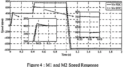
Figure 4 shows the speed response for Ml and M2 motors based on FOC and DTC method respectively. Both motors are able to operate in forward and reverse direction. Different speed demand can be seen during 0.4s to ls show the ability of the FLI to independently control the motors using combined FOC and DTC method. At -750rpm demand, the result shows the ability of the system to perform at 50% voltage utilization
factor with FLI. Further analysis of the speed response during 400rpm speed and no load demand conclude that the DTC method produced lower percent overshoot (%OS) and faster speed response compared to FOC with about 1 %OS and 8%0S respectively. Both methods are able to absorb different external loads applied with a minor speed drop at 0.6s to the motors and before recovering in a few milliseconds
Nセッョ@
·<•OO
·SOOD 11.2 0.4 U,6 0.8 I 1.2 1.4 1.6 l.H
[image:5.595.53.253.231.419.2]Timc(s)
Figure 4 : MI and M2 Speed Response
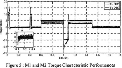
Based on the torque characteristics in Figure 5 , DTC has experienced lower electrical torque response compared to the
FOC which are about 12Nm and 16Nm respectively.
In
this case, the torque component is limited to I ONm for DTC or I OAfor FOC. In DTC, torque is directly controlled while in FOC the torque is controlled by the torque current component. The torque can be analyzed during no load condition at 400rpm,
[image:5.595.316.532.473.592.2]OTC experienced 0.3Nm while FOC shows 0.5Nm. Overall, torque· analysis has shown the FOC has a higher torque ripple compared to DTC.
RPQLNNNNMMNLNNMMNNMMセ L MMイMM[LMM[LNMMMZイMM[MMWセ][Ztセ・ヲセocZZゥャ@
IS - -セMMM
--+- --:- --:- --+---:-
MMセM Mt セ dtc@HI MMセMMM MMtMMセMMMZM
_ _ _J _ _ _
I
,..ri:-,---,_ -L - - _J - -
-I I
__ ).. __ J __ _
I I
- + - - -:- - - - · . - ·
- .1 - - - ' - - - L - - J-I I I I
- .1- - - ' - - - L - _ J _
-1 I I I
·i...,--=o.'="2 ....,.,-to.4 -
T
- -
セ@- - -
.l ' L .J-O.:? 0.4 11.6 0.8 I
T 1111c(5)
I I I I
[image:6.595.315.544.40.158.2] [image:6.595.51.263.77.196.2] [image:6.595.45.267.284.390.2]1.2 1.4 1.8
Figure 5 : MI and M2 Torque Characteristic Performances
Figure 6 depicts phase A current of Ml and M2. Based on the current responses, the higher currents occurred during start up condition, during speed reversal and when external loads were applied. From the torque response, higher load condition experience higher stator current and vice versa. This is in line with the motor operation principle.
I
! I I I I I I I
キゥMMLMMMイMMイMMLMMM イ MMtMMセMMMイMMQMM
セ@ : : I I : I l I :
g $ - - "T - - - 1
o I I
e
<
"
セ@
Figure 6 MI and M2 Phase A stator current characteristic performances
Figure 7 shows %THD in phase A current at 400rpm for Ml and M2. The fundamental current for Ml is 2.358 and M2 .is 2.307. Motor Ml produced higher THD content compared to M2 with 9.97% and 3.57% respectively. The presence of TIID in the phase current becomes the main factor of electromagnetic torque ripple in the motors. Thus, FOC produces higher torque ripple compared to DTC in this system.
Fuz11b.1na11al (I l.J)lbJ • 2_15g. rn-p,i Qj N YWセセ@
1110,, _ . , . . . - - , . . - - , - - - - , - - - , - - - . , . . - - - , . - - - , - - - - ,
I l I I
セM MMセMMMセMMMセ MM MMセMMMサMMMセMMMMセMMM
! I I I I I I
セM MMセMMMQMMMセMMMMセMMMエMMMセMMMMセMMM
j I 1 I I 1 I I
セMセMMセMMMQMMMTMMMMセMMMᄋMMMTMMMMセMMM
I I I I I I 1 I
セM MMセMMMセMMMセMMMMセMMMKMMMセMMMMセMMM
' I I I I
1, I
so 100 150 200
ft('lj_UUIC)' (Ht) ?SO JOO JlO <Oo
llJU
I
.;; &O I
セ@
-,-;; 611 _,_
"il I J! ';; •o
-·-I t 1 1 I I I
--r,,- r y,- r
---1 I I 1 I I l
__ L ___
1 NャMMMセMMMMlMMMャMMMセMMMMlMMMI I 1 I I II I I 1 I I I
MMセMMMQMMMTMMMMセMMMᄋMMMTMMMMセMMM
,;. I I I t I I
セ@ ?O
-,-
I--r---,---,----r---1--- ,-- --r---
I I I I I I II 1 I I I I I
0 so 100 lSO 100 isn :too .'SO 4110 Fn-qumcy (HI.)
(b)
Figure 7 Phase A stator cu1Tent at 400rpm (a) for MI and (b) for M2
VI. CONCLUSION
This paper presents the development of a combined vector control and DTC methods to independently control two induction motors fed by single FLI. The results show the ability of the proposed method to control motor speed independently under forward-reverse step speed command and load disturbance condition. The DZM SVPWM is able to combined vector control and DTC methods to generate switching pattern to the FLI according to the variation speed and load demand.
VII. ACKNOWLEDGEMENT
The authors would like to acknowledge their gratitude to Faculty of Electrical Engineering Universiti Teknikal Malaysia Melaka for providing the resources and support in this study.
REFERENCES
[I] D. Casadei, F. Profumo, G. Serra, and A. Tani, "FOC and DTC: two viable schemes for induction motors torque control," Power Elec1ronics.
IEEE Trar1sactio11s on, vol. 17, pp. 779-787, 2002.
[2] G. S. Buja and M. P. Kazmierkowski. "Direct torque control of PWM inverter-fed AC motors - a survey," Industrial Eleclronics. IEEE
Tra11sac1ions on. vol. 51, pp. 744-757. 2004.
[3] A. Furuya, K. Oka, and K. Matsuse, •A characteristic analysis of four-leg inverter in two AC motor drives with independent vector control," in Electrical Machines and Systems, 2007. ICEMS. International Conference on, 2007, pp. 619-624.
[4]
[5]
[6]
K. Matsusc, N. Kezuka. and K. Oka, "Characteristics of Independent Two Induction Motor Drives Fed by a Four-Leg Inverter," lnd11st1y
Applications. IEEE Trn11sactions 011. vol. 4 7, pp. 2125-2 134, 2011 .
M. Jones, D. Dujic, and E. Levi, "A performance comparison of PWM
teclmiques for five-leg VS!s supplying two-motor drives," in Jnd11s1rial
Electronics, 2008. !ECON 2008. 341/i Annual Conference of IEEE,
2008, pp. 508-513.
M. Jones, S. N. Vukosavic. D. Dujic, E. Levi, and P. Wright, "Five-leg inverter PWM technique for reduced switch count two-motor constant
(a) power applications," Electric Power App/icatio11s. JET, vol. 2. pp. 275-287, 2008.
(7] A. Hara, H. Enokijima, and K. Matsuse, "Independent vector control of two induction motors fed by a five-leg inverter with space vector modulation," in Jnd11s1ry Applications Society Annual Mee1ing (/AS).
201/ /EEE.2011,pp.1-8.
[8] Y. Kimura, M. Hizume, and K. Matsuse, "Independent vector control of two PM motors with five-leg inverter by the expanded two-arm modulation method," in Power Elec1ro11;cs and App/icatio11s, 2005 European Conference on, 2005, pp. 7 pp.-P.7 .
[9] K. Oka, Y. Obama, H. Kubota, I. Miki, and K. Matsuse, "Characteristic
of Independent Two AC Motor Drives Fed by a Five-Leg Inverter," in lndust1y Applicalions Socie1y Annual Meeting, 1009. !AS 2009. IEEE,
2009, pp. 1-8 .
(10] T . Kominami and Y. Fujimoto, "Inverter with Reduced Switching-Device Count for Independent AC Motor Control," in Industrial Eleclro11ics Society, 1007. JECON 2007. 33rd Annual Conference of1/re IEEE, 2007, pp. 1559-1564.
[I l] K. Oka and K . Matsuse, "A nine-switch inverter for driving two AC motors independently," IEEJ TransacJ;ons on Efeclrical and Electronic Engineering, vol. 2, pp. 94-96, 2007.
[12] B.K.Bose, Ed ., Modern Power Elec1ro11ic and AC Motor Drh•e. Prentice Hall PTR, 2002, p."pp. Pages.
[13] C. Lascu, I. Boldea, and F. Blaabjcrg, "A modified direct torque control for induction motor sensorless drive," Jnd11s1ry Applications. IEEE Transac1;ons 011, vol. 36, pp. 122-130, 2000 .
(14) M. Zelechowski, M. P. Kazmierkowski, and F. Blaabjerg, "Controller design for direct torque controlled space vector modulated (DTC-SVM) induction motor drives,• in Industrial Electro11ics. 1005. IS/£ 2005. Proceedings of 1/Je IEEE flllernali.onal Symposium on, 2005 , pp.
951-956 vol. 3.
(15] M. P. Kazmierkowski and P. Wojcik, "Reliable Direct Torque Control with Flux Vector Modulation (DTC-FVM) for AC Motors," in Diagnostics for Electric Machines, Poll'er Electro11ics a1td Dril'eS, 2007. SDEMPED 2007. IEEE !1tter11a1io11al Symposium 01t, 2007, pp. 191-196.
[16] D. Dujic, M. Jones, E. Levi, and S. N. Vukosavic, "A two-motor centre-driven winder drive with a reduced switch count," in Industrial Electronics, 2008. IECON 2008. 34th Annual Conference of IEEE, 2008, pp. 1106-1111.