DOI: 10.12928/TELKOMNIKA.v11i4.1039 691
Study of an Improved Fuzzy Direct Torque Control of
Induction Motor
Dong Ming*1, Tang Yong-qi2, Song Hai-liang1, Wang Bing-jie2
1
Hunan University of technology, Zhuzhou, China 2Hunan Institute of Engineering, Xiangtan, China *Corresponding author, e-mail: [email protected]
Abstrak
Kendali torsi langsung konvensional pasti akan menghasilkan riak torsi karena cara estimasi fluks-nya. Untuk mengatasi masalah ini, strategi kendali baru disajikan pada makalah ini. Strategi ini mengkombinasikan kendali pembagian sektor tegangan vektor dan kendali logika fuzi pada pengendalian torsi langsung tradisional. Pada model ini, logika fuzi menggabungkan sudut fase dari fluks, galat fluks dan galat torsi sebagai variabel fuzi dan mengkelaskan variabel fuzi ini, agar mengoptimalkan pilihan vektor ruang tegangan, dan pada saat yang sama regulator PID tradisional digantikan dengan regulator fuzi. Hasil simulasi menunjukkan adanya perbaikan yang signifikan atas tanggapan torsi, pengurangan riak torsi dan strategi ini memiliki kinerja yang lebih baik pada kondisi dinamis dan stabil, terutama di daerah kecepatan rendah.
Kata kunci: torque ripple; direct torque control; fuzzy control; vectors subdivision; fuzzy speed regulator
Abstract
The conventional direct torque control will inevitably produce torque ripple because of its way of flux estimates. For the purpose of handling this problem, a new control strategy was presented in this paper. This strategy combined subdivides control with voltage vector and fuzzy logic control in traditional direct torque control. In this model, the fuzzy logic combined the phase angle of the flux, the flux error and torque error as fuzzy variables and classified these fuzzy variables, in order to optimize the choice of voltage space vector, and the same time the traditional PID regulator is replaced by a fuzzy regulator. Simulation results show that, a great improvement torque responses , a great reduction of torque ripples is achieved and the strategy has a better dynamic and steady performance, especially in low-speed area.
Keywords: torque ripple; direct torque control; fuzzy control; vectors subdivision; fuzzy speed regulator
1. Introduction
Direct torque control (DTC) technology was a new high performance variable frequency speed-regulating system after vector control. The DTC is characterized by the absence of PI regulators, coordinate transformations, current regulators and PWM signals. The DTC is a kind of directly on the analysis of the stator coordinate of in an induction motor drive of the mathematical model. According to a moment of torque error e , and the stator flux error e,
select a voltage of space vector to limit torque errors and stator flux errors within a relatively small zone. This control mode has a fast response and a simple structure. However, this method has a major drawback is that the torque ripple, because in a sampling period the direct torque control can only choose one switching vector voltage to control the amplitude and rotation speed of the stator flux [2], which is not the expected vector voltage. This is a key why the stator and torque control have a large deviation.
This paper aimed to take advantage of fuzzy logic technique to solve the problems mentioned above. This paper is used a fuzzy logic control to replace conventional PID of speed-loop. This fuzzy logic control can adjust torque real time according to the speed error and the speed rate of change. And then another fuzzy logic combines the phase angle of the flux, the flux error and torque error as fuzzy variables and classificated these fuzzy variables, in order to optimize the choice of voltage space vector. This system has a great flux and torque follow, and improves the robustness of the system also.
2. Principles of DTC
The coordinate system of the three-phase stator electromagnetic torque of the induction motor mathematical model:
(1)
where s and
r are the stator and rotor flux vectors,n
pis the number of the pole pairs,L
is the synthesis of a variety of inductance, and
is the angle of the stator flux vector and the rotor flux vector.From (1) we can get the conclusion that the electromagnetic torque of the induction motor is decided by the multiplication cross of stator flux and rotor flux, and the amplitude of the stator flux is a constant value, the amplitude of rotor flux is usually determined by the load, so the electromagnetic torque of the induction motor is decided by composed of a stator flux and the rotor flux angle. However the angle of rotor flux cannot be mutated, we can only use the voltage vector to control the angle of the stator flux to control the electromagnetic torque. Make the stator flux walking through the addition of six voltage vectors and make the stator flux stop through the addition of two zero vectors. And we can use this method to make the stator flux to run and stop repeatedly to achieve the control of the electromagnetic torque.
2.1 Space voltage vector synthesis and flux interval subdivision
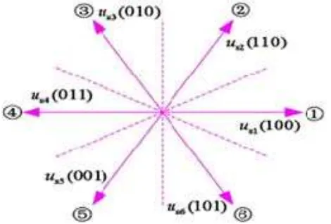
In order to improve the control performance of the system effect, we can use space vector pulse width modulation (SVPWM), the synthesis voltage vector can be any direction at any amplitude. Based on this theory we can synthesize 12 working voltage vectors: six traditional working voltage vectors and six synthesized working voltage vectors (30 degrees each voltage vector). The new synthesized voltage vector is shown in Fig 1.The basic voltage vectors are solid lines and the synthesized voltage vectors are dashed lines.
Figure 1. Synthesized voltage vector
3 1
3 1
sin
2
p s2
p s nTe
n
r
n
r
L
L
3. Fuzzy controller schematics and design
Fuzzy control method is a kind of intelligent control; it can be in accordance with the controller’s input automatically adjust the corresponding control strategy, enabling faster and more accurately mimic the experience of experts, especially it can deal with imprecise model
and uncertainties. In this fuzzy controller, the flux error
E
, the torque errorE
Te and the angleof flux
are the inputs, and the output is the signal of power switches.The Figure 2 is shown that the schematic of fuzzy direct torque control.
Figure 2 Fuzzy controller schematics
3.1 The option of fuzzy variables
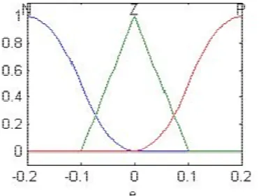
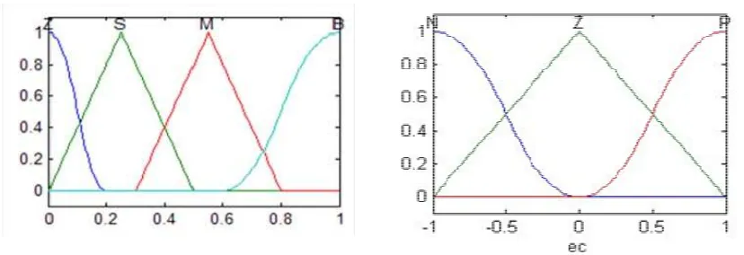
Fuzzy control inputs are the corresponding fuzzy language, therefore we need to be conversed the flux error, the torque deviation, and the flux angle to the corresponding fuzzy language. According to the requirements of the control, we divide the flux error into three fuzzy sets: P for positive, N for negative, Z for zero. We divide the torque error into five fuzzy sets: PB for positive big, PS for positive small, NB for negative big, NS for negative small, Z for zero. In
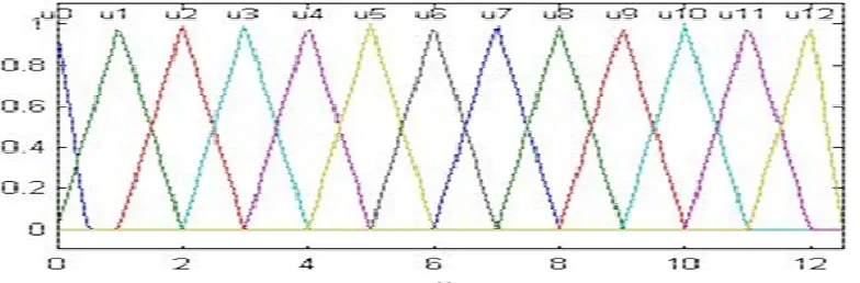
order to make the control actually, we divide the angle of the flux into 12 sections (
1
12).The output of fuzzy control is 12 synthesized working voltage vectors
Figure 5 flux angle membership distribution
Figure 6 fuzzy output membership distribution
3.2 The rule of fuzzy control
Fuzzy control inputs ate the flux deviation, the torque deviation, flux angle, the output is the corresponding switching signal. The rules of fuzzy control are:
:
,
,
i i Te i i i k
R
if
E
A E
B
and
N then
n
u
Where
A
istands for the fuzzy sets of the flux error,B
i stands for the fuzzy sets of thetorque error,
C
istands for the fuzzy sets of the angle of flux,N
istands for the fuzzy sets of power switches signal.Reference voltage vector and flux angle control experience can be summed up 180 rules. The table 1 is shown the rules of fuzzy control
4. The design of the fuzzy speed regulator
For precise control of speed, we must add a speed feedback loop. The conventional speed regulator is conventional PID control, but when the external environment changes or our control requirements change, the PID parameters cannot be real-time changes as our control requirements need. It has a very serious impact on the control requirement we want. In this paper, we use fuzzy PI replace the conventional PID controllers, so that the parameters of PI can adjust automatically the external environment and the control requirement of the system.
Table 1. Fuzzy control rule table
E
E
Te
1
2
3
4
5
6
7
8
9
10
11
12N
PL 5 6 7 8 9 10 11 12 1 2 3 4
PS 6 7 8 9 10 11 12 1 2 3 4 5
ZE 7 8 9 10 11 12 1 2 3 4 5 6
NS 8 9 10 11 12 1 2 3 4 5 6 7
NL 9 10 11 12 1 2 3 4 5 6 7 8
Z
PL 4 5 6 7 8 9 10 11 12 1 2 3
PS 6 7 8 9 10 11 12 1 2 3 4 5
ZE 0 0 0 0 0 0 0 0 0 0 0 0
NS 10 11 12 1 2 3 4 5 6 7 8 9
NL 10 11 12 1 2 3 4 5 6 7 8 9
P
PL 3 4 5 6 7 8 9 10 11 12 1 2
PS 2 3 4 5 6 7 8 9 10 11 12 1
ZE 1 2 3 4 5 6 7 8 9 10 11 12
NS 12 1 2 3 4 5 6 7 8 9 10 11
NL 11 12 1 2 3 4 5 6 7 8 9 10
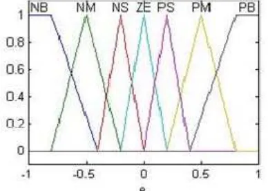
Figure 7 Speed error membership distribution Figure 8 Rate of speed error membership distribution
The rules of fuzzy speed regulator are:
where
A
istands for the fuzzy sets of the speed error,B
i stands for the fuzzy sets of the rate ofspeed error,
ki
stands for the fuzzy sets of the proportion parameters,kp
stands for the fuzzy sets of integration parameters.Figure 9. PI parameters membership distribution
The Tables 2-3 are shown the rules of fuzzy speed control.
Table 2 The rules of kp
e
e
NB NM NS ZE PS PM PB
N B M S M S M B
Z B M B Z B M B
P B M B Z B M B
Table 3. The rules of ki
e
e
NB NM NS ZE PS PM PB
N Z S M B S S Z
Z Z S M B B S Z
P Z M B B S M Z
5 .System Simulation and Analysis
The parameters of the induction motor are:
- Pn=3.7kw,Un=460V,f=50Hz,
- Stator Resistance: 0.435
, Stator Inductance:0.004H,- Rotor Resistance: 0.816
, Rotor Inductance 0.004H,- Mutual Inductance: 0.069H, Sampling period of system:50
Figure10. Fuzzy control direct torque control system model
6.2 Simulation and Analysis
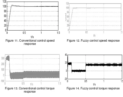
Figures 11 and 12 show the performances of the speed response of the motor at 100 rad/sec and no load for conventional direct torque control and fuzzy direct torque control before t=0.5s.And it clearly shown that the fuzzy direct torque control has no undershoot and it response more quickly than conventional direct torque control.
Figure 11. Conventional control speed response
Figure 12. Fuzzy control speed response
Figure 13. Conventional control torque response
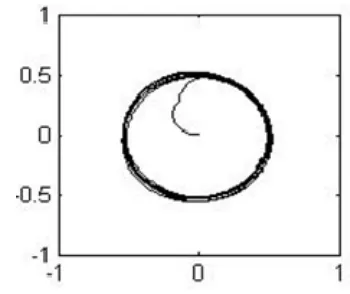
Figure 15. Conventional control flux response Figure 16. Fuzzy control flux response
Figures 13 and 14 show the performances of the torque response of the motor at 100rad/sec. When the motor starts, the starting torque and torque ripple is much smaller than conventional methods, so that it very helpful to reducing the starting current of the motor and device system. Figures 15 and 16 show the performances of the flux ripple. The fuzzy direct torque control has very good static and dynamic response.
6. Conclusion
Direct torque control is a modern high-performance AC speed control method. A fuzzy logic based direct torque control system is implemented in this paper to improve the performance of conventional DTC system. This controller enables to the system to choose optimal stator voltage vectors producing the most suitable rate of torque change according to the 12 fuzzy variables. Simulation results have shown the effectiveness of the proposed method. The fuzzy controller makes some improvement in reducing torque ripples, faster torque response, and stability at very low speed.
References
[1] Li Su. Direct torque control of induction motor. Beijing: Mechanical Industry Press. 1994.
[2] Zhang Jiyong, Liu Xianxing, Wang Deming. Improved direct torque control for induction motor sensor less drive. Computer Measurement & Control. 2004; 12(3): 1-8.
[3] Huang Zhen-xiang, Guo Yan-wen,Liao Jian-xia. Application of Flux Section Subdividing Control in DTC. Proceedings of the CSU-EPSA. 2008.
[4] He De-hua, Liu Guo-rong, Wei Tin-ghua. Study of Torque Ripple Minimization for Direct Torque Control of Induction Motors. Drive and control. 2011; 10.
[5] Xiao An-wen, She Zhi-ting. Application of Fuzzy Control Technology in the Direct Torque Control of an Induction Motor. Journal of Changsha Communications University. 2005; 21(2): 1-10.
[6] Gao Sheng-wei, Wang You-Hua, Cai Yan, Zhang Chuang. Research on Reducing Torque Ripple of DTC Fuzzy Logic-based. 2010 2nd International Conference on Advanced Computer Control (ICACC). 2010; 2: 631-634..
[7] YAN Wei-Sheng, LIN Hai, LI Hong, Yan Wei. Sensor less Direct Torque Controlled Drive of Brushless DC Motor based on Fuzzy Logic. 4th IEEE Conference on Industrial Electronics and Applications 2009. ICIEA 2009: 3411-3416.
[8] Turki Y. Abdalla, Haroution Antranik Hairik, Adel M. Dakhil. Minimization of Torque Ripple in DTC of Induction Motor Using Fuzzy Mode Duty Cycle Controller. 2010 1st International Conference on Energy, Power and Control (EPC-IQ). 2010: 237-244.