“I hereby declare that I have read through this report entitle “Simulation of Direct Torque Control of induction machine using 3-level Cascaded H-Bridge Multilevel Inverter” and found that it has comply the partial fulfilment for awarding the degree of Bachelor of
Electrical Engineering (Power Electronic and Drives)”.
Signature : ...
Supervisor’s Name : Dr.AUZANI BIN JIDIN
SIMULATION OF DIRECT TORQUE CONTROL OF INDUCTION MACHINE
USING THREE-LEVEL CASCADED H-BRIDGE MULTILEVEL INVERTER
MOHAMAD RASYIDI BIN NAZIR ALI
A report submitted in partial fulfilment of the requirements for the degree of Bachelor of Electrical Engineering (Power Electronic and Drives)
Faculty of Electrical Engineering
UNIVERSITI TEKNIKAL MALAYSIA MELAKA
I declare that this report entitle “SIMULATION OF DIRECT TORQUE CONTROL OF INDUCTION MACHINE USING THREE-LEVEL CASCADED H-BRIDGE MULTILEVEL INVERTER” is the result of my own research except as cited in
the references. The report has not been accepted for any degree and is not concurrently submitted in candidature of any other degree.
Signature : ...
Name : MOHAMAD RASYIDI BIN NAZIR ALI
ACKNOWLEDGEMENT
Alhamdulillah, I would like to take this opportunity to express my profound gratitude and deep regards to my supervisor, Dr. Auzani Bin Jidin for his exemplary guidance, monitoring and constant encouragement throughout the course of this thesis. The help and guidance given by him time to time shall carry me a long way in the journey of life on which I am about to embark.
I also would like to thanks to all the lecturers that give advice to me especially to both my panel for this Final Year Project. Besides that, I wish to thanks my study partner, Muhd Zharif Rifqi Zuber Ahmadi which gives a lot of idea during this project. I also would like thanks to my fellow course mate for giving me support and share their idea throughout the project.
ABSTRACT
ABSTRAK
TABLE OF CONTENTS
TABLE OF CONTENTS
3.2.3 Performing switching frequency calculation Algorithm 30
3.2.4 Simulation block model of DTC of induction Machine utilizing CHMI 31
3.2.5 Verification of the effectiveness of the Simulation 32
TABLE OF CONTENTS
CHAPTER TITLE PAGE
4 RESULT 34
4.1 Introduction 34
4.2 Simulation constructed using Matlab 34
4.3 Simulation results 36
4.4 Data tabulation of switching frequency 38
4.5 Three dimensional graph representation 43
4.6 Waveform result 47
5 CONCLUSION 50
5.1 Conclusion 50
5.2 Recommendation 51
REFRENCES 52
LIST OF TABLES
TABLE TITLE PAGE
2.1 Voltage vector selection table 10
3.1 Number of possible voltage space vector to be selected 20
3.2 Voltage vectors selection table for 3-level CHM Inverter 28
4.1 Motor and control parameter 36
4.2 Switching frequency (Hz) at 300 rpm 40
4.3 Switching frequency (Hz) at 300 rpm 40
4.4 Switching frequency (Hz) at 650 rpm 41
4.5 Switching frequency (Hz) at 650 rpm 41
4.6 Switching frequency (Hz) at 1000 rpm 42
LIST OF FIGURES
FIGURE TITLE PAGE
1.1 Limited voltage vector in conventional inverter lead to
Inappropriate selection of switching occurs 2 2.1 Summarization on the evolution of control technique scheme 6 2.2 Topology of Voltage Sources Inverter (VSI) 7 2.3 Voltage space vectors of a 3-phase inverter with the
corresponded switching states 8
2.4 Control of flux magnitude using a 2-level hysteresis comparator 8 2.5 Summary of flux error status in hysteresis band 9 2.6 Control of torque using a 3-level hysteresis comparator 9 2.7 Summary of torque error status in hysteresis band 9 2.8 Definition of six sectors of the stator flux plane 10 2.9 A conventional control structure of DTC-hysteresis based
induction machine 11
2.10 Three phase three level of neutral point clamped 13 2.11 Three phase three level flying capacitor multilevel inverter 14 2.12 Three levels CHMI connected to 3-phase induction machine 15 3.1 Simplified topology 3 Level Cascaded H-bridge Multilevel
Inverter connected to 3-phase induction machine 19 3.2 Typical waveform of the flux, the flux error and the flux
error status for the two-level hysteresis torque comparator 22 3.3 Control of torque using a 7-level hysteresis comparator 23 3.4 Summary of torque error status in hysteresis band 23 3.5 Typical waveform of the torque, the torque error and the torque
error status for the three-level hysteresis torque comparator 24 3.6 The sector definition of (a) the stator flux plane for long and
LIST OF FIGURES
FIGURE TITLE PAGE
voltage vector 25
3.7 Two possible active voltage are switched for each sector to control the stator flux within its hysteresis band 25 3.8 Definition of sector for short and long amplitudes of voltage
vectors 26 3.9 Finalized voltage space vectors of 3-level Cascaded H-Bridge
Multilevel 27
3.10 A de-couple control structure of DTC of induction machine
using CHMI 29
3.11 Voltage vectors available in (a) 2-level inverter and (b) 3-level Cascaded H-Bridge Multilevel Inverter 32 3.12 Summarization on procedure to construct optimum look-up
table for CHMI 33
4.1 Simulation result on Matlab of a de-couple control structure of DTC of induction machine 35 4.2 Performance comparison of torque control based on selection
of vectors using (a) 2-level inverter (b) CHMI 37 4.3 Magnified simulation result obtain (a) 2-level inverter (b) CHMI 38 4.4 Switching frequency variation at 300 rpm (a) Conventional (VHZ)
(b) CHMI (VHL) 44
4.5 Switching frequency variation at 650 rpm (a) Conventional (VHZ)
(b) CHMI (VHL) 45
4.6 Switching frequency variation at 1000 rpm (a) Conventional (VHZ)
(b) CHMI (VHL) 46
LIST OF FIGURES
FIGURE TITLE PAGE
(c) CHMI (d) zoom image of CHMI 48 4.8 Comparison the switching frequency at medium speed operation.
(a) Conventional inverter (b) zoom image of conventional inverter (c) CHMI (d) zoom image of CHMI 45 49 4.9 Comparison the switching frequency at high speed operation.
LIST OF APPENDICES
APPENDIX TITLE PAGE
LIST OF ABBREVIATION
DTC Direct Torque Control FOC Field Oriented Control VSI Voltage Sources Inverter
CHMI Cascaded H-Bridge Multilevel Inverter
NPC Neutral Point Clamped
CHAPTER 1
INTRODUCTION
1.1 Overview
In the real industry world, control of induction machine play a vital role as it has many
application in real work place. Induction machine has several advantages such as rugged, less
complex and affordable in price. Direct torque control (DTC) is a vector based control
technique that proposed in early 1980 where it involves the combination control of torque and
flux by feedback and closed loop estimation process. A comprehensive researches and latest
update based on this control technique has been proved by hundreds of paper related to this
DTC are published since the last two decade. Furthermore, DTC only required information of
resistance in stator which make it simpler control technique compared to field oriented control
(FOC) which required both stator and rotor parameters. Nowadays, development of multilevel
inverter recently has been a solution to the major problem highlighted in conventional inverter
since it provides more effective voltage selection. For instance, cascaded H-Bridge multilevel
inverter (CHMI), neutral point clamped (NPC) and flying capacitor multilevel inverter (FCMI)
are among the three multilevel inverters that popular and many research related this have been
publish. This is because the advantages that highlighted by multilevel inverter such as ability
to achieve high power from medium source, can generate the output voltages with very low
distortion and reduce the rate of change of voltage (dv/dt) which improve the electromagnetic
Figure 1.1: Limited voltage vector in conventional inverter lead to inappropriate selection of
DTC technique that proposed using conventional inverter has several disadvantages
such as less selection of effective voltage vector hence lead to high switching frequency. The
limited voltage vectors selection are as shown in Figure 1.1 which comprise of six voltage
amplitude. Less effective voltage vector happen because the fixed of two level in the
conventional inverter has cause inappropriate selection of switching occur especially when
changes of the speed happen. The high rate change of voltage (dv/dt) has cause increase in
torque ripple [1]. By this improper selection of switch also lead to the increase in switching
frequency. High switching frequency has cause losses to the operation of induction machine
and increase possibility of overshoot to happen [1].
Therefore, by replacing the conventional inverter with the CHMI it bring significant
improvement since the level of effective voltage has increase and lead to more strategy
switching state during changes of speed occurs. By having proper selection of effective
voltage vector, the torque ripple reduces [1]. Therefore, the efficiency of direct torque control
of induction machine improves by the minimization of torque ripple since the switching
(i) To formulate n optimal voltage vector selection according to speed operations for DTC
of induction machine.
(ii) To verify the proposed selection of voltage vectors can improve efficiency and reduce
torque ripple.
1.4 Scope of research
The scope of this project focuses on the development of optimal look-up table for DTC
utilizing on 3-level CHMI by using simulation only. The simulation was carried out using
Matlab/Simulink simulation package. The simulation is then verified by adding switching
frequency algorithm to the DTC simulation to carry the analysis. Comparison between 3-level
CHMI and conventional inverter will be discussed after the final result is achieved to highlight
the advantages of 3-level CHMI.
1.5 Report outline
The general description of this report outline is discussed in this subsection. Basically
these reports are based on five chapters. The executive summary was provided before the first
chapter to give overview of the whole project.
First and foremost, chapter one provides overview to give better understanding of the
project. This chapter also highlights the significant of the problem statement, objective and
scope of the project.
The second chapter provides information based on the conventional and basic topology
of the project. The previous works based on the previous research will be discussed in detail to
simulation. The result will be proving in the chapter four where it based on the work done in
previous chapter.
Last but not least, conclusion section provide summary of the whole project.
Recommendations based on the finding during the project also will be emphasize for the
CHAPTER 2
LITERATURE REVIEW
2.1Theory
2.1.1 Introduction
The process of undertaking a literature review is an integral part of doing this project
on simulation of DTC of induction machine using 3-level CHMI. It is a critical evaluation to
gain an understanding of the continuously research on various control technique of induction
machine and the advances strategies used in latest development of multilevel inverter. This
section also will discuss the review of technical report that related to latest finding in DTC and
CHMI. Thus provides a clear, better and deeper understanding on technique to improve
2.1.2 Control technique
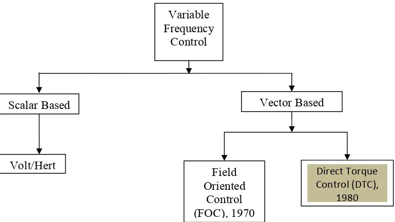
Generally the control techniques to control speed of induction motor are based on
scalar and vector control. Firstly, scalar controls proposed less complex technique to working
with and bid better steady-state response. However, the dynamic response take long times
since the transient are uncontrollable. Frequency of voltage and current is the parameter to be
controlled in scalar. Early in 1970, to control induction machine, the field oriented control
which emphasize on the principle of torque and flux control was introduced. Later on, a
decade after, DTC was proposed. Figure 2.1 summarized the flowchart of variable frequency
control. The highlight part to indicate the focuses of this project that is DTC.
Direct Torque
This subsection provides a review about conventional three phase two level inverter.
Inverter function basically is to convert direct current (DC) to alternating current (AC). Figure
2.2 shows three phase VSI that contain six numbers of insulated gate bipolar transistor
(IGBTs) or gate turn-off thyristor (GTOs) where each leg made up of a pair power switching
devices. This power switching devices is complimentary to one another on operation. For
instance, when voltage is supply to the IGBTs, if upper switch (Sa1) is ON the lower switch
(Sa2) must be OFF and vice versa.
In general, the switching state can have 8 different possibilities of switching from the
equation 2n, where n=3 are the number of legs contain in VSI. The possibilities are show in Figure 2.3 based on type of voltage vector plotted by the given equation [2.1]
Vk
=
VDC (Sa +aSb+a2Sc) where a = / and k = 0, 1, 2 ...7. (2.1)where Vk is the different possibilities of switching in voltage space vector
Figure 2.2: Topology of Voltage Sources Inverter (VSI)
2.1.4 Basic principle in direct torque control (DTC)
In order to construct a look-up table, the basic principle in general must be followed to
ensure all the requirement parameter included in this part. Three important parameter in this
part is flux error status, torque error status and sector definition. Firstly, direct flux control are
as shown in Figure 2.4 where the flux error enter the two level hysteresis comparator to
produce flux error status φ+ either 0 or 1. The error is obtaining by comparing the reference input flux,
φ
s, ref and estimated stator flux,φ
s. The summary of this process are highlighted inFigure 2.5.
Figure 2.4 Control of flux magnitude using a 2-level hysteresis comparator 1
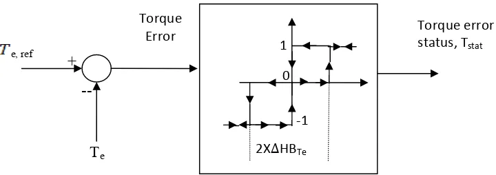
Beside flux, torque also needs to be controlled. Secondly, DTC are as shown in Figure
2.6 where the torque error enter the three level hysteresis comparator to produce torque error
status, Tstat either 1,0 or -1. The errors are obtained by comparing the reference input torque,
Te,ref and estimated torque flux, Te. The summary of this process are highlighted in Figure 2.7.
Last but not least are the sector definitions, which are divided equally to six sectors.
For example, Figure 2.8 illustrates on how the flux is increased and decreased with the use of
voltage vectors V1and V2respectively when it lies in Sector II. This pattern continuous for one
completes cycle with the pattern increase and decrease by the use of different voltage vector. 1 Touches upper band, active forward voltage vector
0 Touches middle band, zero voltage vector selected Torque error status
-1 Touches lower band, active reverse voltage vector +
Figure 2.6: Control of torque using a 3-level hysteresis comparator 0
1
‐1
1 Touches lower band, stator flux need to be decrease
0 Touches upper band, stator flux need to be increase
Figure 2.5: Summary of flux error status in hysteresis band Flux error status