Faculty of Electrical Engineering
IMPLEMENTATION OF DIRECT TORQUE CONTROL OF
BRUSHLESS DC MOTOR UTILIZING DIGITAL SIGNAL
PROCESSOR
Ahmad Faiz Bin Noor Azam
Master of Electrical Engineering (Industrial Power)
IMPLEMENTATION OF DIRECT TORQUE CONTROL OF BRUSHLESS DC MOTOR UTILIZING DIGITAL SIGNAL PROCESSOR
AHMAD FAIZ BIN NOOR AZAM
A dissertation submitted
in fulfilment of the requirements for the degree of Master of Electrical Engineering (Industrial Power)
Faculty of Electrical Engineering
UNIVERSITI TEKNIKAL MALAYSIA MELAKA
DECLARATION
I declare that this thesis entitle “Implementation of Direct Torque Control (DTC) of
Brushless DC Motor Utilizing Digital Signal Processor” is the result of my own research
except as cited in the references. The thesis has not been accepted for any degree and is not
concurrently submitted in candidature of any other degree.
Signature : ………
Name : ………
APPROVAL
I hereby declare that I have read this thesis and in my opinion this thesis is sufficient in
terms of scope and quality for the award of Master of Electrical Engineering (Industrial
Power) .
Signature : ………
Supervisor Name : ………
DEDICATION
i
ABSTRACT
ii
ABSTRAK
iii
ACKNOWLEGMENTS
I take this opportunity to express my profound gratitude and deep regards to my supervisor
Dr. Auzani bin Jidin for his exemplary guidance, monitoring and constant encouragement
throughout the course of this thesis. The help and guidance given by him time to time shall
carry me a long way in the journey of life on which I am about to embark.
I also take this opportunity to express a deep sense of gratitude to all co members of Power
Electronics and Drive Group for sharing valuable information, interest and guidance,
which helped me in completing this task through various stages.
I am obliged to staff members of University Teknikal Malaysia Melaka (UTEM) for the
valuable information provided by them in their respective fields. I am grateful for their
cooperation during the period of my master project. I also would like to give my
appreciation to UTEM and CRIM for appointing me as a graduate research assistant
(GRA) which helps me in terms of financial which raise my motivation in completing this
master.
Lastly, I thank almighty, my parents, my wife, daughter and son, brother and sisters and
friends for their constant encouragement without which this thesis would not be possible.
iv
LIST OF SYMBOLS AND ABBREVIATIONS xi
LIST OF PUBLICATIONS xiv
CHAPTER
2. LITERATURE REVIEW OF DIRECT TORQUE CONTROL 13
2.0 Introduction 13
3. METHOD OF RESEARCH: SIMULATION AND HARDWARE 39
v
3.3 Hardware Implementation 73 3.3.1 Introduction 73 3.3.2 DS1104 R&D Controller Board (DSPACE) 77 3.3.3 Control Desk Configuration 79 3.3.4 Altera Field Programmable Gate Array – Cyclone III DEO 81 Board
3.3.5 Gate Drivers and Three Phase Voltage Source Inverter 83 3.3.6 BLDC Motor 86
3.4 Conclusion 88
4. RESULTS AND DISCUSSION 89
4.0 Introduction 89 4.1 Evaluation of DTC Performance 90
4.2 Conclusion 96
5. CONCLUSION AND FUTURE WORK 97
5.0 Conclusion 97
5.1 Future Work 98
REFERENCES 99
vi
LIST OF TABLES
TABLE
2.1
3.1
3.2
3.3
3.4
TITLE
The variation of with Different Voltage Vector.
Complete summary of the Modes of BLDC Drive
Voltage Vector Selection Table as Proposed in (Ozturk and Toliyat, 2007)
Identification of The Six Sectors in the α-β Plane Based on Hall-Effect Signals.
BLDC Motor parameters
PAGE
27
53
56
57
vii
Control structure of basic DTC hysteresis based induction machine.
Schematic diagram of Voltage Source Inverter (VSI).
Voltage space vectors of a three phase inverter with the combination of switching states.
Flowchart of the research.
Schematic diagram of VSI.
Voltage space vector.
Six equally divided sectors of the stator flux plane.
Block diagram of the stator flux hysteresis comparator.
Typical waveforms of the stator flux, the flux error and the flux error status for the two level hysteresis flux comparator.
Two possible active voltage vector for each sector to control the stator flux within its hysteresis band.
The variation of with application of (a) active voltage vector (b) zero or radial voltage vector, (c) reverse voltage vector.
Three level torque hysteresis comparator.
Typical waveforms of the torque, the torque error and the torque error status for three level hysteresis comparator.
Four quadrants operation.
Control Structure of hysteresis based DTC of BLDC Motor.
viii
BLDC motor cross section and phase energizing sequence.
Three phase DC to AC inverter.
Three phase BLDC machine equivalent circuit and mechanical model.
Ideal torque or back-emf voltage factor and current waveform for each phase (The output of Hall Effect sensors according to the rotor position are also given in the figure).
BLDC mathematical model in laplace form.
Schematic of a three phase BLDC motor connected to an inverter.
Definition of voltage vector.
Complete simulation of BLDC motor model.
VSI in simulation.
Torque hysteresis controller.
DTC of BLDC motor drive block diagram.
Torque and sector estimation block.
Block diagram of the experimental setup.
MATLAB simulation for the Experimental Setup.
Laboratory experiment setup.
DS1104 R&D controller board.
Control desk configurations.
Altera FPGA – Cyclone III DEO board.
Block diagram of voltage vectors selection table and blanking time generation.
Block diagram of blanking time generation for a single leg (i.e phase a).
Gate driver schematic diagram.
ix
Schematic of the IGBT module with the capacitor snubbers.
Simulation results of electromagnetic torque, d-axis voltage, q-axis voltage and sector ( constant torque of 0.7 N.m).
Experimental results of electromagnetic torque, d-axis voltage, q-axis voltage and sector (constant torque of 0.7 N.m).
Simulation results of electromagnetic torque, phase A current, phase B current and phase C current (for step of change of reference torque from -0.3 N.m to -1.2 N.m)
Experimental results of electromagnetic torque, phase A current, phase B current and phase C current (for step of change of reference torque from -0.3 N.m to -1.2 N.m)
Simulation results of electromagnetic torque, phase A current, phase B current and phase C current (for step of change of reference torque from 0.3 N.m to 1.2 N.m)
x
LIST OF APPENDICES
APPENDIX
A
B
C
TITLE
Machine Equations
Details of MATLAB Simulation
VHDL Code
PAGE
102
107
xi
LIST OF SYMBOLS AND ABBREVIATIONS
ADC
Analogue to Digital Converter
Viscous friction
Flux density of the field in which the conductors are placed
Brushless DC Motor
Complex Programmable Logic Device
Digital to Analogue Converter
Direct Self Control
Digital Signal Processor
Direct Torque Control
Motor back EMF in stationary reference frame
Electromotive Force
Field Oriented Control
Field Programmable Gate Array
d and q components of the stator current in stationary reference frame
Incremental Encoder
Induction Machine
Moment of Inertia
xii
Back EMF constant of one phase
Length of the conductor, m
Mutual Inductance
Stator and Rotor self-inductance
Number of conductors in series per phase
No. of poles
Personal Computer
Permanent Magnet
Permanent Magnet Synchronous Motor
Pulse Width Modulation
Radius of the rotor bore, m
Stator Resistance
Electromagnetic Torque
Load torque
Velocity, m/s
Line to Neutral Voltage
DC Link Voltage
Very high speed integrated circuit, Hardware Description Language
Voltage Source Inverter
Rotor angle
Stator and rotor flux linkage space vectors in general reference frame.
Stator and rotor flux linkage space vectors in stationary reference frame.
xiii -
-
-
-
-
Electrical rotor angle
Mechanical rotor angle
Rotor speed
Electrical rotor speed
xiv
LIST OF PUBLICATIONS
NO.
1
2
3
TITLE
AHMAD FAIZ BIN NOOR AZAM , M. B. M., AUZANI BIN JIDIN , NORHAZILINA BINTI BAHARI, , HATTA BIN JOPRI, ABDUL RAHIM BIN ABDULLAH 2012. Torque Hysteresis Controller for Brusless DC Motor Drives. Power and Energy Conversion Symposium (PECS 2012).
AZAM, A. F. N., JIDIN, A., NGATIMAN, N. A., JOPRI, M. H., MANAP, M., HERLINO, A. L. & ALIAS, N. F. 2013 Current control of BLDC drives for EV application. Power Engineering and Optimization Conference (PEOCO), 2013 IEEE 7th International, 3-4 June 2013. 411-416.
1
CHAPTER 1
INTRODUCTION
1.0 Research Background
Conventional dc motors are highly efficient and their characteristic makes it
reliable for use in many applications. However, the only drawback is that it uses
commutator and brushes that require frequent maintenance and cannot be performed at
dirty and explosive environment and at very high speed operating conditions.
Maintenance-free motor can be developed by replacing the functions of commutator and
brushes by solid-state switches, and these types of motors are now known as Brushless DC
(BLDC) motors. BLDC motors are, in fact, a type of permanent magnet synchronous
motors (PMSM). It is driven by dc voltage, and the current commutations are done by
solid-state switches.
BLDC motor has advantages of longer lifespan, faster torque response and
capability of high speeds drive in comparison with DC motor (Jeon et al., 2000). BLDC
motor implements the basic operating principles of DC motor operation but with a
difference by placing the permanent magnet in the rotor and coils in the stator. The coil
windings are electrically separate from each other, which allow it to be turn on and off in a
2
so that excitation of the stator field always leads the permanent magnet field to produce
torque. The commutation instants are determined by the rotor position, and the position of
the rotor is detected either by position sensors or by sensorless techniques. The signals
from Hall Effect sensors that usually used in BLDC motor need to be decoded to determine
the shaft position and appropriate excitation of stator windings.
The three phase power electronic converter is necessary to operate the BLDC
machine. The converter converts DC to AC via six solid-state semiconductor switches.
MOSFET and IGBT are the most common types of switches being used. In lower power
application, MOSFET are preferred over IGBT. The power electronic inverter must be
capable of applying positive, negative and zero voltage across the motor phase terminals.
Each drive phase consists of one motor terminal driven high, one motor terminal driven
low, and one motor terminal floating.
1.1 Significance of Research
This research is based on the popularity of BLDC motor drives as mentioned
above, i.e. high-torque density, high-speed operations, free-maintenance, etc. The BLDC
motor drives require precise and robust control of torque, as well as current limiter to avoid
inrush current due to sudden large torque demand especially during acceleration modes.
Traditionally, the method of hysteresis torque/current controller was used to meet the
above requirements. However, this conventional method operates the inverter at three
phase conduction mode, in which produces high switching frequency as well as switching
losses. In addition, the three phase conduction mode in this method may degrade the
3
i.e. switching frequency/losses by applying DTC method with two-phase conduction mode
as proposed in (Ozturk and Toliyat, 2007) for a BLDC motor. The DTC operation of
two-phase conduction mode is verified via simulation and experimental results.
1.2 Overview of Modern BLDC Motor Drives
Vector control and DTC drives are the two types of instantaneous electronic torque
controlled AC drives used for high-performance applications. The first vector control
which is called Field Oriented Control (FOC) was introduced more than 25 years ago in
Germany by Hasse, Blaschke (Blaschke, 1972). FOC transforms the motor equations into
a coordinate system that rotates in synchronism with the rotor flux vector. There is a linear
relationship between the control variables and the torque when operating under constant
rotor flux amplitude. FOC drives achieved a high degree of maturity and established in
worldwide markets.
DTC was introduced in Japan by Takahashi and Nagochi (Takahashi and Noguchi,
1986) and also in Germany by Depenbrock (Depenbrock, 1988). DTC is a method that
uses a bang-bang / hysteresis control instead of a decoupling control which symbolizes the
characteristic of a vector control. The hysteresis control technique works well with the
on-off operation of the switches (i.e MOSFET and IGBT). DTC controls the electromagnetic
torque and flux linkage directly and independently using six or eight voltage space vectors
as defined in the lookup table. Lookup table is constructed to choose appropriate switching
states of the inverter which the selection is based on the output of the hysteresis controller
4
DTC technique was first introduced in the late 1980’s to drive the induction
machine; however, the method has been absorbed to the other types of AC drives to
improve the existing results. Now researchers are focusing on combining the DTC
techniques with PMSM / BLDC machines, as reported in (Ozturk et al., 2010, Ozturk and
Toliyat, 2007, Ozturk and Toliyat, 2011, Rahman et al., 2004, Yong et al., 2005, Yong et
al., 2007, French and Acarnley, 1996, Lixin et al., 2003, Seog-Joo and Seung-Ki, 1995,
Sung Jun et al., 2000, Zhong et al., 1997, Zhu et al., 2005). DTC scheme for induction
machines still has a few drawbacks, which are the high torque and stator flux linkage
ripples, switching frequency that varies with load torque, rotor speed and the bandwidth of
the hysteresis controllers. Researchers have been working to reduce the torque and flux
ripple and fix the switching frequency of the DTC system as reported in (Buja et al.,
1997b, Buja et al., 1997a, Casadei et al., 1995, Jidin et al., 2011a, Jidin et al., 2011b, Jidin
et al., 2012, Takahashi and Noguchi, 1997). A modified DTC scheme with fixed switching
frequency and low torque and flux ripple was introduced in (Jidin et al., 2010).
For DTC of BLDC, the back EMF integration for the stator flux linkage calculation
requires the knowledge of stator flux position during start up. In order to find its position in
the circular trajectory it needs to be sensed by position sensor, but it is not desired due to
its cost and bulky characteristics; therefore, some initial position sensing methods are
required for DTC of BLDC applications. (Noguchi et al., 1998) proposed a method for
detecting the initial rotor position estimation at the standstill for PM motors. A better
solution was introduced for the rotor position estimation by applying high-frequency
voltage to the motor; this method is adopted in the DTC of BLDC motor for initial position
5
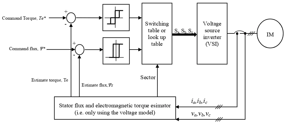
1.3 Overview of Basic DTC
A simple control structure of basic DTC was introduced by Takahashi. The
structure consist a pair of hysteresis controllers, switching table / lookup table for voltage
vectors selection, a three phase voltage source inverter (VSI) and lastly flux and torque
estimators as shown in Figure 1.1. In DTC, torque and flux are controlled by satisfying
their demands simultaneously using appropriate voltage vector selection. Then the voltage
vector is used either to increase or decrease the torque and stator flux based on the criteria
of torque error status, flux error status and flux orientation.
Figure 1.1 Control structure of basic DTC hysteresis based induction machine.
The motor operating condition which includes the rotor speed, stator and rotor
fluxes and DC link voltage influence the torque and flux slope criteria hence affecting the
switching pattern of the hysteresis comparators. Furthermore, the switching frequency of
the VSI also gets affected by the operating conditions. A three phase VSI consists of six
switching devices (i.e IGBT, MOSFET, GTO, etc.) which transform the DC link voltage to
the AC voltage source. From Figure 1.2, it can be seen that the VSI is connected to a wye
Switching
Stator flux and electromagnetic torque esimator (i.e. only using the voltage model)
ia,ib,ic
va,vb,vc
Sa, Sb, Sc