PORTABLE WIND POWER SYSTEM
AHMAD FADZIL BIN ZAINUDIN
i
PORTABLE WIND POWER SYSTEM
AHMAD FADZIL BIN ZAINUDIN
B010610164
This Report Is submitted in partial Fulfillment of Requirements for the Degree of
Bachelor in Mechatronics Engineering
Faculty of Electrical Engineering
UNIVERSITI TEKNIKAL MALAYSIA MELAKA ( UTeM )
ii
“ I hereby declared that this PSM report is a result of my own work, as clearly stated in the sources of reverences and sources is explained and stated . “
Signature : ……….
Name : Ahmad Fadzil bin Zainudin
IC No. : 871110-06-5969
iii
“I hereby declared that I have read through this report and found that it has complied the partial fulfillment for awarding the degree of Bachelor of Mechatronics Engineering. “
Signature : ………
Supervisor’s Name : Miss Aziah Binti Khamis
Date : 12th May 2010
iv
ACKNOWLEDGEMENT
In preparing this report, I was in contact with many people, researchers, academicians and practitioners. They have contributed towards my understanding and thought. In particular, I wish to express my sincere appreciation to my main project supervisor, Miss Aziah Binti Khamis, for encouragement, guidance critics and friendship. Without her continued support and interest, this project would not have been same as presented here.
v
ABSTRACT
vi
ABSTRAK
vii
TABLE OF CONTENT
CHAPTER TITLE PAGE
ACKNOWLEDGEMENT iv
ABSTRACT v
ABSTRAK vi
TABLE OF CONTENT vii
LIST OF FIGURES x
LIST OF TABLE xii
1 INTRODUCTION 1
1.1 Problem statement 2
1.2 Objectives 3
1.3 Scope of project 3
1.4 Outline of Thesis 4
2 LITERATURE VIEW 5
2.1 Theory of wind 5
viii
2.4.1 Off-Grid Wind-Electric Systems 11
2.4.2 Grid-Tied Wind-Electric System with
Battery Backup 12
2.4.3 Batteryless Grid-Tied Wind-Electric
System 13
2.4.4 Direct-Drive Batteryless Wind-Electric
System 14
2.5 Charge controller (Electronic control system) 15
ix
CHAPTER TITLE PAGE
3 METHODOLOGY 23
3.1 Project Flowchart 24
3.2 Charge controller 25
3.3 Circuit simulation 26
3.4 Wind turbine 28
3.5 Battery Bank 30
3.6 Setting up Trip Points 31
3.7 Hardware Layout 32
4 RESULT AND OUTCOME 34
4.1 Expected result 34
4.2 Charge controller 35
4.2 Trip points 37
4.3 Wind turbine test 38
4.4 Circuit simulation 39
5 CONCLUSION AND RECOMMENDATION 40
5.1 Conclusion and recommendation 40
REFERENCE 42
x
LIST OF FIGURES
FIGURE TITLE PAGE
1.1 Project block diagram 4
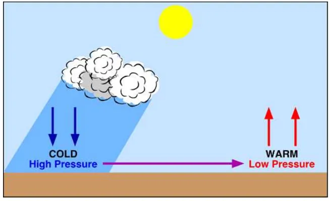
2.1 Formation of wind as a result of pressure difference 5
2.2 Formation of wind as a result of localized temperature differences 6
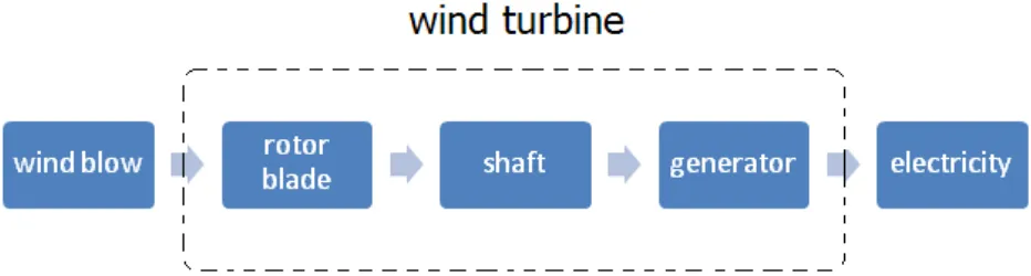
2.3 Wind power block diagram 7
2.4 Vertical (left) and horizontal (right) wind turbine 8
2.5 Wind turbine structure 9
2.6 Off-Grid Wind-Electric Systems 11
2.7 Grid-Tied Wind-Electric System with Battery Backup 12
2.8 Batteryless Grid-Tied Wind-Electric System 13
2.9 Direct-Drive Batteryless Wind-Electric System 14
2.10 Wind charge controller 15
2.11 Example of solar charge controller circuit diagram 16
2.12 General block diagram of inverter 17
2.13 Square-wave inverter circuit diagram 18
2.14 The output voltage of square-wave inverter 18
2.15 Lead-acid battery 19
xi
2.17 SIMULINK features 21
2.18 Mini Wind Turbine Eco-Friendly Charger 22
2.19 Orange Power Pump Charger by GotWind 23
2.20 How to operate product 23
3.1 Flow of the project 24
3.2 Charge controller circuit diagram 25
3.3 Simulation on Charge controller on ISIS LITE 27
3.4 12 Vdc PC cooling fan 29
3.5 Lead-acid Battery 30
3.6 Setting up TP-A and TP-B 31
3.7 Hardware Layout Design 32
3.8 Main parts of hardware 33
4.1 Charge controller 35
4.2 Discharge state 36
4.3 Multimeter reading at TP-B 37
4.4 Multimeter reading at TP-A 38
xii
LIST OF TABLE
TABLE TITLE PAGE
3.1 Comparison of motor types 28
3.2 PC fan Specification 29
1
CHAPTER 1:
INTRODUCTION
The law of conservative energy states that energy neither can be created nor can be destroy. In most situations, it changes its form from one type to another. There are many forms of energy (kinetic, light, heat, electrical, potential) and most of it has been used in daily life. For the past centuries, human have been working on changing energy form to satisfy human needs. As the result, many facilities invented through energy conversion. One of the examples is vehicles move through conversion of combustion energy of fuel to kinetics energy. The recent engineering and technologies are focusing on using electrical energy as power source. But the current methods of producing electrical energy have lot of disadvantages and one of it is its cost and effect on global warming.
2
This project wills attempt to implement this concept of electricity generation but in smaller scale. Wind turbine will be build along with generator, electronic control system and energy storage such as battery banks. As for the output, the power store should be able to empower Direct Current (DC) loads. Converting wind power to electricity will involve two major processes that are generates and process. The fundamental idea of the project is to process, store and use electrical energy produce from conversion and generation of wind energy which is the second part of the wind power.
1.1 Problem statement
Converting wind energy to electrical power will meet several problems. Beside of its massive power, the properties of wind explain that it is very unstable energy and so thus the power produce. Exceed energy can damage wind turbine and components in electrical control system. To overcome this, a smarter system needed in order for the generator to withstands. It is a system which is able to monitor wind velocity and alarms the control system if the wind exceed generator limit for further action. The selection of battery is also a vital part of the project because it has a risk to be damage if not properly secure. The battery use must be the most suitable to cope with instability of power generates. Other than that, it is necessary for the battery to have enough capacity to store power generates because its durability is important to empower frequent-use appliances in vehicle.
3
itself. One of the ways to resolve this matter is to dump the power to high-wattage resistors. But it cause heat to be release and might not be suitable in vehicle.
1.2 Objectives
There are four objective of this project: 1. To convert wind energy to electricity.
2. To build charge controller to monitor the system. 3. To simulate electronic circuit to obtain expected data.
4. To build prototype and successfully use electrical energy for DC load.
1.3 Scope
The scopes of the project are:
1. Electricity generated from wind turbine flow through blocking diode to electronic control system.
2. 6V SPDT relay sends the turbine power either to the battery bank or to the dump. 3. The incoming voltage divided in half by pair of resistor. Dual operational amplifier
compare voltage to decide whether to send power to be recharge or to the dump. 4. The trip points for full-charge is 7.4 V and discharge is 5.9 V
4
Figure 1.1: Project block diagram
1.4 Outline of thesis
5
CHAPTER 2
LITERATURE VIEW
2.1 Theory of wind
Wind is simply air in motion. It is caused by the uneven heating of the Earth's surface by the sun. Because the Earth's surface is made of very different types of land and water, it absorbs the sun's heat at different rates. During the day, the air above the land heats up more quickly than the air over water. The warm air over the land expands and rises, and the heavier, cooler air rushes in to take its place, creating wind. At night, the winds are reversed because the air cools more rapidly over land than over water. In the same way, the atmospheric winds that circle the earth are created because the land near the Earth's equator is heated more by the sun than the land near the North and South Poles.
6
The above figure shows the formation of air movement as a result of pressure difference. To describe the process of wind formation, the blue ―H‖ represents high pressure and the red ―L‖ is lower pressure. On the figure above, pressure is indicated by drawing isolines, called isobars, at regular 4 mb(millibar) intervals. The highest pressure in the figure is 1012 mb and the lowest is 984 mb. This difference in pressure causes the air move from higher to lower pressure region. This motion can be in any direction, but in most cases the horizontal component of wind flow greatly exceeds the flow that occurs vertically. Colder region result higher air pressure and warmer region cause lower pressure. Figure 2.2 below shows formation of wind through temperature difference.
Figure 2.2: Formation of wind as a result of localized temperature differences.
7
2.2 Wind power
The terms wind energy or wind power describes the process by which the wind is used to generate mechanical power or electricity. The most common technique to convert wind power is by using a wind turbine. Wind turbines convert the kinetic energy in the wind into mechanical power. This mechanical power can be used for specific tasks (such as grinding grain or pumping water) or a generator can convert this mechanical power into electricity. Air is a fluid like any other except that its particles are in gas form instead of liquid. And when air moves quickly, in the form of wind, those particles are moving quickly. Motion means kinetic energy, which can be captured, just like the energy in moving water can be captured by the turbine.
The strength of wind varies, and an average value for a given location does not alone indicate the amount of energy a wind turbine could produce there. Different locations will have different wind speed distributions. The motion of wind can be in any direction, but in most cases the horizontal component of wind flow greatly exceeds the flow that occurs vertically. Since wind speed influence by the difference of temperature between two regions, wind speed tends to be at its greatest during the daytime when the greatest spatial extremes in atmospheric temperature and pressure exist.
8
2.3 Wind Turbine
A wind turbine is a rotating machine which converts the kinetic energy of wind into mechanical energy. If the mechanical energy is used directly by machinery, such as a pump or grinding stones, the machine is usually called a windmill. If the mechanical energy is instead converted to electricity, the machine is called a wind generator, wind turbine, wind power unit (WPU), wind energy converter (WEC), or aero generator. Wind turbines require locations with constantly high wind speeds. With a wind resource assessment it is possible to estimate the amount of energy the wind turbine will produce.
Like old fashioned windmills, today‘s wind turbines (also called wind machines) use blades to collect the wind‘s kinetic energy. The wind flows over the blades creating lift, like the effect on airplane wings, which causes them to turn. The blades are connected to a drive shaft that turns an electric generator to produce electricity.
2.3.1 Types of Wind Turbines
Modern wind turbines fall into two basic groups: the horizontal-axis variety and the vertical-axis design, like the eggbeater-style Darrieus model, named after its French inventor. Horizontal-axis wind turbines typically either have two or three blades. These three-bladed wind turbines are operated "upwind," with the blades facing into the wind.
9
2.3.2 Inside the Wind Turbine
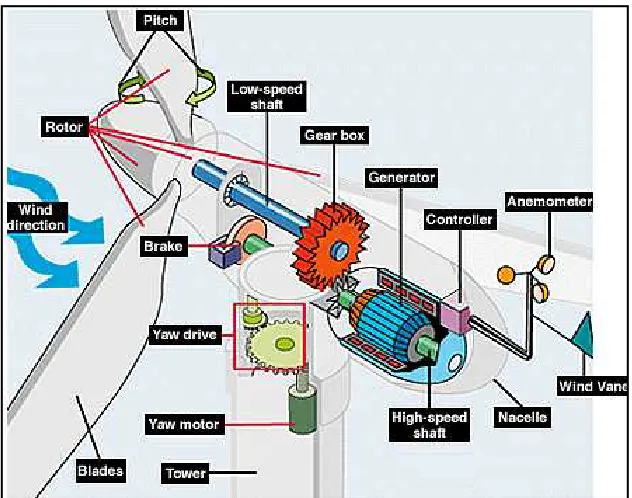
Figure 2.5: Wind turbine structure
Anemometer:
Measures the wind speed and transmits wind speed data to the controller. Blades:
Most turbines have either two or three blades. Wind blowing over the blades causes the blades to "lift" and rotate.
Brake:
A disc brake, which can be applied mechanically, electrically, or hydraulically to stop the rotor in emergencies.
Controller:
The controller starts up the machine at wind speeds of about 8 to 16 miles per hour (mph) and shuts off the machine at about 55 mph. Turbines do not operate at wind speeds above about 55 mph because they might be damaged by the high winds. Gear box:
10
Generator:
Usually an off-the-shelf induction generator that produces 60-cycle AC electricity. High-speed shaft:
Drives the generator. Low-speed shaft:
The rotor turns the low-speed shaft at about 30 to 60 rotations per minute. Nacelle:
The nacelle sits atop the tower and contains the gear box, low- and high-speed shafts, generator, controller, and brake. Some nacelles are large enough for a helicopter to land on.
Pitch:
Blades are turned, or pitched, out of the wind to control the rotor speed and keep the rotor from turning in winds that are too high or too low to produce electricity. Rotor:
The blades and the hub together are called the rotor. Tower:
Towers are made from tubular steel (shown here), concrete, or steel lattice. Because wind speed increases with height, taller towers enable turbines to capture more energy and generate more electricity.
Wind direction:
This is an "upwind" turbine, so-called because it operates facing into the wind. Other turbines are designed to run "downwind," facing away from the wind.
Wind vane:
Measures wind direction and communicates with the yaw drive to orient the turbine properly with respect to the wind.
Yaw drive:
Upwind turbines face into the wind; the yaw drive is used to keep the rotor facing into the wind as the wind direction changes. Downwind turbines don't require a yaw drive, the wind blows the rotor downwind.
Yaw motor:
11
2.4 Wind-Electric system types
2.4.1 Off-Grid Wind-Electric Systems
Off-grid wind-electric systems are battery based. People generally choose these systems because their home or other energy use is not connected to the grid, and connection would be expensive. Others prefer the independence of off-grid systems, or live where utilities and governments make it difficult to tie a renewable energy system to the grid.
Off-grid systems are limited in capacity by the size of the generating sources (wind turbine, solar-electric array, fuel-fired generator, etc.), the resources available, and the battery bank size. Off-grid homeowners have to learn to live within the limitations of their system capacity. The following illustration includes the primary components of any off-grid wind-electric system with battery backup.