i
HOME SECURITY SYSTEM
MUHAMAD HAFIZ BIN NORROSNAN
This report is submitted in partial fulfillment of the requirements for the award of Bachelor of Electronic Engineering(Industrial Electronics) With Honours
Faculty of Electronic and Computer Engineering Universiti Teknikal Malaysia Melaka
UNIVERSTI TEKNIKAL MALAYSIA MELAKA
FAKULTI KEJURUTERAAN ELEKTRONIK DAN KEJURUTERAAN KOMPUTER
BORANG PENGESAHAN STATUS LAPORAN PROJEK SARJANA MUDA II
Tajuk Projek : HOME SECURITY SYSTEM
Sesi
Pengajian :
0 9 / 1 0
Saya MUHAMAD HAFIZ BIN NORROSNAN
(HURUF BESAR)
mengaku membenarkan Laporan Projek Sarjana Muda ini disimpan di Perpustakaan dengan syarat-syarat kegunaan seperti berikut:
1. Laporan adalah hakmilik Universiti Teknikal Malaysia Melaka.
2. Perpustakaan dibenarkan membuat salinan untuk tujuan pengajian sahaja.
3. Perpustakaan dibenarkan membuat salinan laporan ini sebagai bahan pertukaran antara institusi
pengajian tinggi.
4. Sila tandakan ( √ ) :
SULIT*
*(Mengandungi maklumat yang berdarjah keselamatan atau kepentingan Malaysia seperti yang termaktub di dalam AKTA RAHSIA RASMI 1972)
TERHAD** **(Mengandungi maklumat terhad yang telah ditentukan oleh organisasi/badan di mana penyelidikan dijalankan)
TIDAK TERHAD
Disahkan oleh:
__________________________ ___________________________________ (TANDATANGAN PENULIS) (COP DAN TANDATANGAN PENYELIA)
ii
“I hereby declare that this report is result of my own effort except for quotes as cited in the references.”
Signature : ……….
iii
“I hereby declare that I have read this report and in my opinion this report is sufficient in terms of the scope and quality for the award of Bachelor of Electronic Engineering
(Industrial Electronics) With Honors.”
Signature : ……….
iv
For my lovely mum and dad, thanks for your sacrifice towards my success.
For my supervisor, En. Hazli Rafis Bin Abd Rahim, thanks for all your
supports.
v
ACKNOWLEDGEMENT
First and foremost, I would like to give Thanks to ALLAH SWT, for helping me. I would like to express my appreciation to my supervisor, Mr.. Hazli Rafis Bin Abd Rahim for her support and guidance throughout this whole project.
To my beloved parents who always give me support and never tired of convincing me in order to achieve my determination and finishing my study without any delay. They always support me and understand me while giving me opportunity in completing all my projects.
Besides that, I am also thankful to all the lecturers that also giving me some ideas and knowledge that can be used to accomplish the PSM project. Not forgotten to my friends who had also helped me in giving their thought, pro and contra of each of the research and result that I had obtained.
vi
ABSTRACT
vii
ABSTRAK
TABLE OF CONTENTS
CHAPTER TITLE PAGE
I INTRODUCTION 1
1.1 Introduction 1
1.2 Project Summary 1
1.3 Problem Objectives 2
1.4 Problem Statements 2
1.5 Operation Of The Project 4
1.6 Sensor Operation 5
1.7 Scope Of The Project 13
II LITERATURE REVIEW 15
2.1 Literature review overview 15
2.2 Conceptual Logic 15
2.3 Circuit Diagram 16
2.4 Power Supply 19
2.5 Alarm Devices 21
2.6 Instrusion Definitions 23
2.7 Zone Circuit Logic 24
2.8 Keypads 24
III METHODOLOGY 31
3.1 Introduction 31
3.2 Flowchart Description 32
3.3 Gantt Chart 34
3.4 Expected Results 35
IV RESULTS AND ANALYSIS 37
4.1 Introduction 37
4.2 Project Result 37
4.3 Hardware Part 38
4.4 Software part 42
4.5 Simulation part 42
4.6 Project Model 44
4.7 Actual Results 46
V CONCLUSION AND SUGGESTION 48
5.1 Introduction 48
5.2 Discussion 48
5.3 Conclusion 50
5.4 Suggestion and Future Work 51
REFERENCES 52
1
CHAPTER I
INTRODUCTION
1.1 Introduction overview
This chapter discusses about the project objective, project summary, problem statement and operation this project.
1.2 Project Summary
2
sensor can be enabled or disabled, and alarm frequency and skim can also be chosen by users.
1.3 Project Objectives
The main objective of the home security system is to introduce the system to the user to monitor the safety of their homes from burglary. In addition, to introduce the system using PIC Microcontroller to control and monitor all of the houses. This is objectives of the project will be implemented :
• To create and developed a effective home security system. • To design home security system using PIC Microcontroller.
• To find suitable circuit and electronic component to build that system. • To know how the operation of circuit home security system.
• To prove how that system can be used in the house.
1.4 Problem Statements
Security systems are a popular means of crime deterrence in modern society; since most people believe that criminals disregard houses armed with alarm systems. As the market for security systems expanded, the technology and resulting features available in home security systems has also sky-rocketed. Unfortunately, many security system customers are left with a multi-thousand dollar alarm system that they are unable to effectively operate.
3
current status of the system. With recent technological innovations, alarm systems have the capability to report or display far more information than "armed" or "unarmed". Unfortunately, these advances in technology and features have not been accompanied with suitable interface designs.
In order to accomplish this, there must attempt to recognize as many shortcomings in current system interfaces as possible, and attempt to correct these, as well as implement a superior status display system capable of easily imparting more information to the user. There are a number of user needs in the area of security variations that the system should address. Not all users will demand the same type of security, nor do all users want this security at the same time. Additionally, their rationale for desiring this security may vary depending on their possessions or requirements for safety.
The system should be able to provide appropriate levels of security while occupants are away from their residence. This feature, while it is considered a general requirement for all systems, may prove especially helpful for those who put in irregular hours at their place of employment, those who vacation on a regular basis, or even for those who like to do yardwork yet don't like to lock their doors behind them all the time.
4
Other modes of system alertness can vary based on who is in the house. For example, babysitters or housekeepers may wish to secure the house in a more simple manner than someone going to sleep or leaving the house for vacation. The system must be accessible and usable for more than one specified user; it must allow for the needs of all who may occupy the house/property- not just the homeowner.
Finally, much attention has been given to securing the house itself, but for users who desire the safeguarding of items that are not only in their house but on the premises, features must allow for arming of circuits outside of the house. Some applications of this could be the arming of entrances to carports and garages, supply closets, tool sheds, and backyards. In addition, users may wish for this feature to exclude uninvited parties from their property so as to avoid liability claims, such as negligence to safeguard a swimming pool or dangerous equipment.
1.5 Operation Of The Project
5
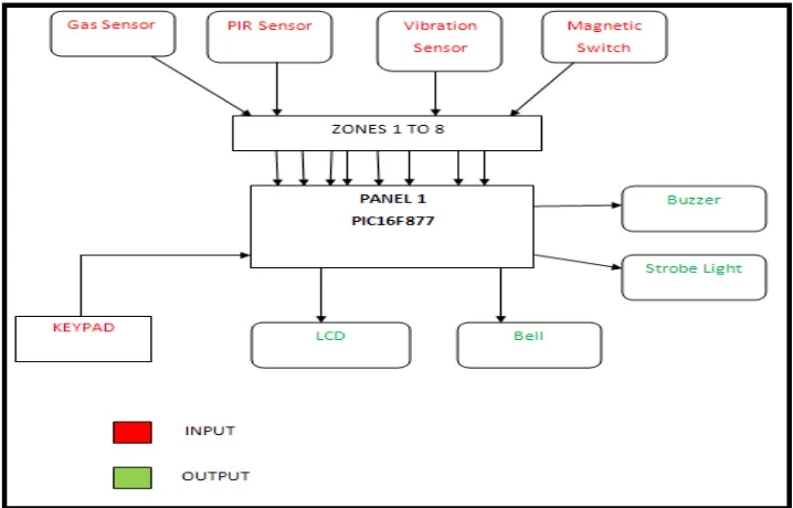
provides anti-tamper warning of interference with the system.This is a block diagram of the Home Security System shown in Figure 1.1: Input : Keypad, Magnetic Switch, Smoke Sensor,Motion Sensor, and Temperature Sensor. Output : Buzzer, Strobe,Bell, and LCD.
Figure 1.1: Block Diagram of the Home Security Systems
1.6 Sensor Operation
1.61 Smoke Sensor
6
1.61.1 Photoelectric Detectors
Occasionally you will walk into a store and a bell will go off as you cross the threshold. If you look you will often notice that a photo beam detector is being used. Near the door on one side of the store is a light (either a white light and a lens, or a low-power laser), and on the other side is a photodetector that can "see" the light. When you cross the beam of light you block it. The photodetector senses the lack of light and triggers a bell. You can imagine that this same sensor could act as a smoke detector. If it ever got smoky enough in the store to block the light beam sufficiently, the bell would go off! There are two problems: 1) it's a pretty big smoke detector, and 2) it is not very sensitive. There would have to be a LOT of smoke before the alarm would go off - the smoke would have to be thick enough to completely block out the light, and that's a lot of smoke.
Photoelectric smoke detectors therefore use light in a different way. Inside the smoke detector there is a light and a sensor, but they are at 90 degree angles to one another, like this: Figure 1.2 as shown below:
7
In the normal case, the light from the light source on the left shoots straight across and misses the sensor. When smoke enters the chamber, however, the smoke particles scatter the light and some amount of light hits the sensor. Figure 1.3 as shown below:
Figure 1.3: The smoke particles scatter the light and some amount of light hits the sensor
The sensor then sets off the horn in the smoke detector. Photoelectric detectors are better at sensing smoky fires, such as a smoldering mattress.
1.61.2 Ionization Detectors
8
microcurie of Americium-241. A curie is a unit of measure for nuclear material. If you are holding a curie of something in your hand, you are holding an amount of material that undergoes 37,000,000,000 nuclear transformations per second. Generally that means that 37,000,000,000 atoms in the sample are decaying and emitting a particle of nuclear radiation (such as an alpha particle) per second. One gram of of the element radium generates approximately one curie of activity (Marie Curie, the woman after whom the curie is named, did much of her research using radium).
An ioniziation chamber is very simple. It consists of 2 plates with a voltage across them, along with a radioactive source of ionizing radiation, like this: Figure 1.4 as shown below:
Figure 1.4: voltage across them, along with a radioactive source of ionizing radiation
9
a free electron (with a negative charge) and an atom missing one electron (with a positive charge). The negative electron is attracted to the plate with a positive voltage, and the positive atom is attracted to the plate with a negative voltage (opposites attract, just like with magnets). The electronics in the smoke detector sense the small amount of electrical current that these electrons and ions moving toward the plates represent.
When smoke enters the ionization chamber it disrupts this current - the smoke particles attach to the ions and neutralize them. The smoke detector senses the drop in current between the plates and sets off the horn.
1.62 Motion Sensor
A motion detector is a device that monitors a field of view and performs a function if motion is detected within that field. The function might be to trigger the opening of a door, as in the case of a grocery store; start a videotape machine for surveillance; turn on floodlights; or sound an alarm. A motion detector might detect motion through the use of optics or acoustics and can be passive or active. Component used to detect movement is PIR, "Passive
Infrared".[4]
10
PIRs are basically made of a pyroelectric sensor (which you can see above as the round metal can with a rectangular crystal in the center), which can detect levels of infrared radiation. Everything emits some low level radiation, and the hotter something is, the more radiation is emitted. The sensor in a motion detector is actually split in two halves. The reason for that is that we are looking to detect motion (change) not average IR levels. The two halves are wired up so that they cancel each other out. If one half sees more or less IR radiation than the other, the output will swing high or low.
Along with the pyroelectic sensor is a bunch of supporting circuitry, resistors and capacitors. It seems that most small hobbyist sensors use the BISS0001 ("Micro Power PIR Motion Detector IC"), undoubtedly a very inexpensive chip. This chip takes the output of the sensor and does some minor processing on it to emit a digital output pulse from the analog sensor. For many basic projects or products that need to detect when a person has left or entered the area, or has approached, PIR sensors are great. They are low power and low cost, pretty rugged, have a wide lens range, and are easy to interface with.
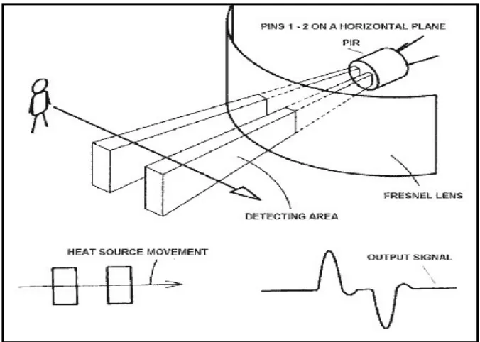
PIR sensors are more complicated than many of the other sensors explained in these tutorials (like photocells, FSRs and tilt switches) because there are multiple variables that affect the sensors input and output. To begin explaining how a basic sensor works, we'll use this rather nice diagram (if anyone knows where it originates plz let me know).
11
outdoors. When a warm body like a human or animal passes by, it first intercepts one half of the PIR sensor, which causes a positive differential change between the two halves. When the warm body leaves the sensing area, the reverse happens, whereby the sensor generates a negative differential change. These change pulses are what is detected. Figure 1.5 as shown below:
Figure 1.5: When the warm body leaves the sensing area, the reverse happens, whereby the sensor generates a negative differential change
1.61 Temperature Sensor
12
temperature helps people to pick their clothing before a walk outside just as it helps chemists to understand the data collected from a complex chemical reaction.[6]
1.63 Magnetic Switch
Magnetic contact switch is a generic term referring to an electrical switch that is operated by a magnetic field. The absence or presence of the magnetic field, provided by a small magnet, opens and closes the switch. In the alarm industry, they are the most common and the most economical form of protection. Generally, there are 3 types of magnetic contact; recessed, surface, and mechanically actuated. The recessed contact shown on the left is the most common in residential applications. The entire switch and magnet are concealed within the fabric of the building and when they are pressed into the 3/8-inch holes drilled for their installation, all that remains visible is a couple of 7/16-inch diameter, slightly raised dots on the esurface. If painted over, they can become very difficult to locate.[7] Figure 1.6 as shown below:
13
Figure 1.6: Magnetic Switch Device
1.7 Scope Of The Project
The scope of this project is to design the Home Security System . This project mainly focuses on hardware and program. It also has some circuit to control all the sensors and keypad input, output information to LCD screen, indicate system status on LED, and make buzz or voice alarm.
1.71 Program
14
1.72 Hardware